 Products Home
高耐荷重回転ステージ、ステッピングモーター付き

- Continuous 360° Motorized Rotation
- 50 kg (110 lbs) On-Axis Load Capacity
- SM2 (2.035"-40) Threaded Central Bore
- Variety of Mounting Options
NR360SP2
Vertical Mounting Bracket
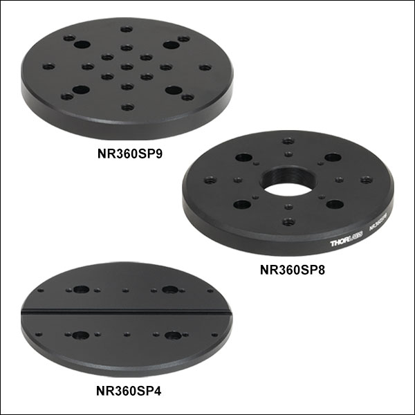
NR360SP8
SM1 Threads and
30 mm Cage System Taps
NR360SP9
Seventeen 1/4"-20 Taps
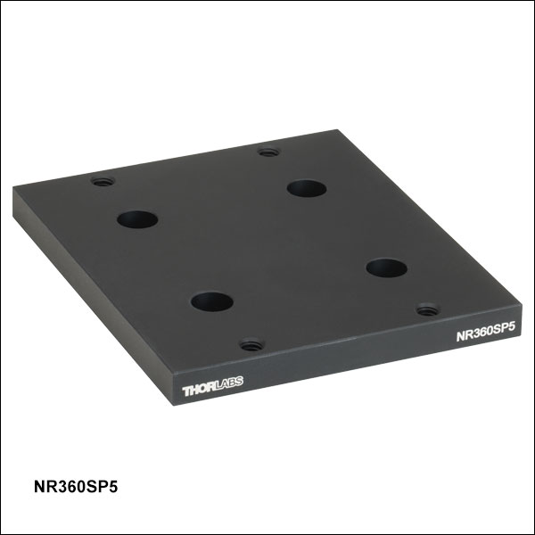
NR360SP5
Adapter for Mounting HDR50 Stage to
LNR50 & NRT Series Translation Stages
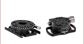
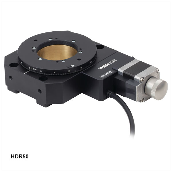
HDR50
Heavy-Duty Rotation Stage with
SM2-Threaded Center Hole
NR360SP4
Groove for Fiber Alignment
Accessories
Top Plate Adapters


Please Wait
| Key Specificationsa | |
|---|---|
| Travel | 360° Continuous Rotation |
| Speedb,c | 50 °/sec (Max) |
| Accelerationc | 80 °/sec2 (Max) |
| Accuracy | ±820 µrad |
| Bidirectional Repeatability | ±350 µrad |
| Minimum Incremental Motion | 0.8 µrad |
| On-Axis Load Capacity | 50 kg (110 lbs) |
| Maximum Torque | 6 N•m |
| Motor Type | 2 Phase Stepper |
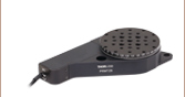
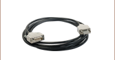
| Included Extension Cable | PAA613, 3 m Long |
Click to Enlarge
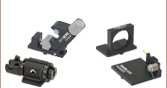
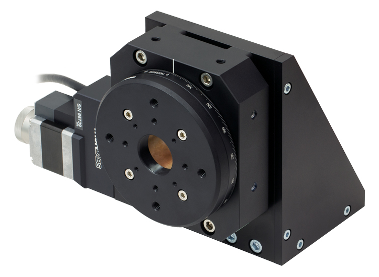
Figure 1.1 ブラケットNR360SP2(/M)で垂直方向に取り付けたアダプタープレートNR360SP8付き
回転ステージHDR50(/M)
(すべて別売り。詳細は下記をご覧ください)。
特長
- 軸上の最大許容荷重:50 kg
- SM2ネジが切られた中央開口部
- オプトメカニクスや上部プレート用アダプタを取り付けるためのM4タップ穴
- プリロードされたウォームギア機構によりバックラッシュを低減
- M4タップ穴で取り付け可能な上部プレート用アダプタ:
- NR360SP9/M:17個のM6タップ穴の付いたアダプタ
- NR360SP8:SM1ネジおよび30 mmケージシステム用タップ穴の付いたアダプタ
- NR360SP4/M:ファイバーアライメントアクセサリ用の溝が付いたアダプタ
- 垂直方向への取り付けや、移動ステージへの取り付けを可能にするアダプタ
- Kinesis®制御用ソフトウェア一式(詳細は「Kinesisソフトウェア」のタブをご覧ください)
- 推奨コントローラ:BSC201
高耐荷重回転ステージHDR50/Mは電動での連続回転が可能で、50 kgまでの重量物を搭載できます。マイクロステッピングモータ、ウォームギアアセンブリ、精密ベアリングなどで構成されており、高さは44 mmと薄型です。ステージ中央の開口には、回転部、非回転部ともにSM2ネジが切られており、SM2レンズチューブを取り付けることができます。また、M6の皿穴が4つあり、ブレッドボードに直接固定できるようになっています。これらの穴の間隔は広くとってあるため、ミリ規格のステージをインチ規格のブレッドボードに取り付けることができ、またその逆も可能です。さらに、側面にある6つのM6取付け穴を利用してポストに取り付けることもできます。
アクセサリ
当社では上部プレート用アダプタを数種類ご用意しています。各アダプタはM4ネジでステージHDR50/Mの回転部に取り付けられます。取り付け用アダプタも2種類ご用意しています。ブラケットNR360SP2/Mを用いると回転ステージを垂直方向に取り付けられ、アダプタNR360SP5/Mを用いると移動ステージに取り付けることができます。
ソフトウェア
ステージは、ユーザーフレンドリーなKinesisソフトウェアパッケージで駆動できます。これにより、複雑な動作シーケンスを素早く設定できます。また、.NETコントロールが使用でき、最新のC#、Visual Basic、LabVIEW™、あるいはその他の.NETに対応する言語を使用してカスタムプログラムを作成するようなサードパーティの開発者も利用することができます。すべての関連する動作パラメータは、当社のステージおよびアクチュエータ製品用のソフトウェアによって自動的に設定されます。詳細については「Kinesisソフトウェア」および「Kinesis チュートリアル」のタブをご覧ください。
| Stage Specifications | |
|---|---|
| Translation and Motion Parameters | |
| Travel | 360° Continuous Rotation |
| Speeda,b | 50 °/sec (Max) |
| Accelerationb | 80 °/sec2 (Max) |
| On-Axis Load Capacity | 50 kg (110 lbs) |
| Drive Mechanism | Worm Drive |
| Gear Ratio | 66:1 |
| Homing Sensor | Hall Effect, Non-Contact |
| Stage Bidirectional Repeatability | ±350 µrad |
| Stage Bidirectional Accuracy | ±820 µrad |
| Minimum Incremental Motion | 0.8 µrad |
| Homing Bidirectional Repeatability | ±203 µrad |
| Axis Wobble | 65 µrad |
| Torque | 6 N•m (Max) |
| Physical Specifications | |
| Platform Size | Ø3.86" (Ø98.0 mm) |
| Central Aperture | SM2 (2.035"-40) Threaded |
| Platform Mounting Holes | Four 8-32 (M4) |
| Dimensions | 7.46" x 4.55" x 1.73" (189.4 mm x 115.5 mm x 44.0 mm) |
| Weight | 3.34 lbs (1.52 kg) |
| Attached Cable Length | 0.5 m |
| Included Extension Cable | PAA613, 3 m Long |
| Operating Temperature Range | 5 °C to 40 °C |
| Humidity | 80% RH at 31 °C (Max) |
| Motor Specifications | |
|---|---|
| Motor Type | 2-Phase Stepper |
| Step Angle | 1.8° (200 Major Steps per Revolution) |
| Micro-Stepping | 2048 Micro-Steps per Major Step (Total of 409,600 Micro-Steps per Revolution) |
| Rated Phase Current | 0.85 A |
| Resistance / Phase | 3.6 Ω |
| Inductance / Phase | 4.6 mH |
モーターケーブルのピン配列
Dタイプオス型
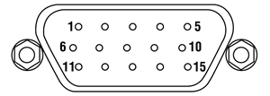
| PIN | Description |
|---|---|
| 1 | Limit Switch Grounda |
| 2 | Not Used |
| 3 | Clockwise Limit Switch Output |
| 4 | Phase B -ve |
| 5 | Phase B +ve |
| 6 | Phase A -ve |
| 7 | Phase A +ve |
| 8 & 9 | Not Used |
| 10 | 5 Vb |
| 11 & 12 | Not Used |
| 13 | 5 Vb |
| 14 | Not Used |
| 15 | Earth |
ソフトウェア
Kinesisバージョン1.14.52
このKinesisソフトウェアパッケージには、当社のKinesisシステムコントローラを制御するためのGUIが含まれています。
下記もご用意しております。
- 通信プロトコル

Figure 58A KinesisソフトウェアのGUI画面
当社のKinesis®ソフトウェアパッケージを用いて、当社の様々なモーションコントローラを駆動することができます。このソフトウェアは小型で低出力のシングルチャンネルドライバ(K-Cube®など)から、高出力でマルチチャンネルのベンチトップ型ユニットやモジュール型の19インチラックナノポジショニングシステム(ラックシステムMMR60x)まで、当社Kinesisシリーズの様々なモーションコントローラの制御用にご使用いただけます。
Kinesisソフトウェアでは.NETコントロールを使用できるため、最新のC#、Visual Basic、LabVIEW™、あるいはその他の.NET対応言語を使用してカスタムプログラムを作成することができます。.NETフレームワークの使用を想定していないアプリケーションのために、ローレベルのDLLライブラリも含まれています。中央シーケンスマネージャ(Central Sequence Manager)は、当社のすべてのモーションコントロール用ハードウェアの統合と同期の機能をサポートしています。
この共通のソフトウェアプラットフォームにより、ユーザは単一のソフトウェアツールを習得するだけで、あらゆるモーションコントロールデバイスを1つのアプリケーション内で組み合わせて使用することができます。このように1軸システム用から多軸システム用までのあらゆるコントローラを組み合わせ、それら全てを1台のPCの統合されたソフトウェアインターフェイスから制御できます。
このソフトウェアパッケージには2つの使い方があります。1つはGUI(グラフィカルユーザーインターフェイス)ユーティリティを用いる方法で、コントローラの到着後すぐに直接的な操作と制御を行なうことができます。もう1つは一連のプログラミングインターフェイスを用いる方法で、ご希望の開発言語によりカスタム仕様の位置決めやアライメント用のプログラムを簡単に作成することができます。
Kinesisソフトウェアでは新しい.NETコントロールが使用でき、最新の最新のC#, Visual Basic, LabVIEW™、ほかの.NET対応言語を使用する開発者がカスタムにプログラムを作成することもできます。
C#
このプログラミング言語はマルチプログラミングパラダイムやマルチプログラミング言語が使用可能となるよう設計されているため、複雑な問題が簡単かつ効率的に解決できます。型付け、命令型、宣言型、関数型、ジェネリック、オブジェクト指向、そしてコンポーネント指向が含まれます。 この共通のソフトウェアプラットフォームにより、1セットのソフトウェアツールを習得するだけで、あらゆるKinesisコントローラを簡単に組み合わせることができます。このようにして1軸システムのコントローラから多軸システムのコントローラまで、様々なコントローラを組み合わせ、全てを1台のPCのソフトウェアインターフェイスから制御することが可能となりました。
Kinesisシステムソフトウェアを使用するには2つの手段があります。コントローラを直接つないで制御を行なう付属のGUI(グラフィカルユーザーインターフェイス)ユーティリティ、またはご希望の開発言語でカスタム仕様の位置決めやアライメントを簡単にプログラムできる一連のプログラミングインターフェイスです。
Kinesisモーションコントロールライブラリの構築の参考となる実行可能なプロジェクト機能拡張例については下のリンクをクリックしてください。なお、Quick Startのプロジェクト例の実行には別の統合開発環境(IDE)(Microsoft Visual Studioなど)が必要です。C#のプロジェクト例はKinesisソフトウェアパッケージに付属する.NETコントロールで実行可能です(詳細は「Kinesisソフトウェア」タブをご覧ください)。
 | Click Here for the Kinesis with C# Quick Start Guide Click Here for C# Example Projects Click Here for Quick Start Device Control Examples | |
LabVIEW
LabVIEWは、.Netコントロールを介してKinesisベースのコントローラとの通信に使用できます。LabVIEWでは、ツールとオブジェクトでフロントパネルとして知られるユーザーインターフェイスを構築した後、グラフィカル表記の関数を使ってコードを追加し、フロントパネルのオブジェクトを制御します。下記のLabVIEWチュートリアルでは.Netコントロールを使用してLabVIEW内Kinesis駆動デバイス用の制御GUIを作成するための情報をご提供しています。 LabVIEWでコントローラを制御する基本的な方法や、LabVIEW GUIを用いてデバイスを操作する前に行うべき設定の手順についても解説しています。
 | Click Here to View the LabVIEW Guide Click Here to View the Kinesis with LabVIEW Overview Page | |
| Posted Comments: | |
Thomas Arnold
(posted 2024-05-15 15:59:17.87) Will the HDR50/M also work with a K-Cube stepper controller or is the BSC201 necessary? spolineni
(posted 2024-05-21 09:29:42.0) Thank you for your enquiry. The HDR50/M is specifically engineered to work optimally when paired with either the BSC20x benchtop stepper motor controllers or the MST602 modular stepper motor control unit. In the K-cube series, although the KST201 can control the HDR50/M, it may not deliver full performance across all speed ranges and load capacities. Jingke Zhang
(posted 2024-03-25 21:35:18.26) Hi, when I home my HDR50 stage, the stage does not stop when it reaches the 0/360 degrees and keep rotating until I manually stop it. How can i fix it? Thank you! spolineni
(posted 2024-04-03 06:00:45.0) Thank you for contacting us. Sorry to know that you’re experiencing an issue with this stage. Please be assured that I will personally reach out to you to address and resolve it. DEUK NYEON KIM
(posted 2023-12-05 09:42:46.01) Please inform the following situation
First, I press the homming button HDR50/M rotation stage. but location of 0 position is not matched white line.
I think that the calibration file needs to be correct position... Second, i moved somewhat travels. and matched 0 position and white line. i want to save some setting files that this position is new homming position, and reload setting files, then machine go homed position. but i dont know how save the settings..... do'neill
(posted 2023-12-12 04:25:36.0) Response from Daniel at Thorlabs. A change to the zero offset can be made using the custom settings. I will reach out to you directly to discuss your application and walk you through changing this. Connor Flynn
(posted 2022-05-26 13:30:40.047) Is is possible to obtain the HDR50 without the stepper motor? I have my own stepper motors that I already have software to drive so do not need or desire the HDR50 stepper motor. What would be the cost of an HDR50 without stepper motor included? DJayasuriya
(posted 2022-05-27 09:34:18.0) Thank you for your inquiry. Unfortunately this would not be possible due to the design of the device. We have got in touch with you to discuss your application. Jussi Tykkä
(posted 2020-11-03 07:57:40.527) What is the IP-rating of the HDR50? cwright
(posted 2020-11-03 08:25:25.0) Response from Charles at Thorlabs: Hello and thank you for your query. Our stages are designed to be used within an indoor lab environment and so have not been tested for ingress protection. We will reach out to see if we can advise on suitability for your application. Warren Massey
(posted 2020-05-22 07:12:03.84) The manual says that the homing/limit sensor is a 5VDC Hall switch and that the signal line from the switch is pin #3 on the 15-pin connector. What is the part number of that hall switch? When the stage is at its home position and the switch is in its active state, is pin #3 grounded or at 5 volts? DJayasuriya
(posted 2020-06-02 03:26:51.0) Thank you for your inquiry, we will get in touch with you directly to resolve your issue. Wenzel Jakob
(posted 2020-05-20 17:56:27.293) When I home my NR360S stage (predecessor of HDR50), the white marker line does not align with the "0" degree position. Is there any way to fix that? It's not a huge problem, but it can be convenient to know where the homed position will be when setting up an experiment. DJayasuriya
(posted 2020-05-22 10:45:10.0) Thank you for your inquiry. We will get in touch with you directly to assist you to adjust this. Md Rashedul HUQE
(posted 2020-01-06 22:27:01.03) Dear Concern,
I have an inquiry regarding HDR50/M. We are plan to use HRD50/M for our ellipsometry project for polarizer and analyzer. Is that stepper motor have Zero position option. What do you mean by Homing Bidirectional Repeatability in the specification?
Thank you
Rashed cwright
(posted 2020-01-07 09:16:27.0) Response from Charles at Thorlabs: Hello Rashed, the repeatability specification is a measure of a stage's ability to return to a commanded position. i.e. how close it will be to the original position.
Bidirectional repeatability is an average of the repeatability when the commanded position is approached from both directions and is regarded as a more descriptive way of specifying repeatability. Thorlabs specifies this value as the bidirectional repeatability with backlash correction enabled.
The homing bidirectional repeatability is the bidirectional repeatability the stage can achieve when finding it's zero (home) position.
"Is that stepper motor have Zero position option." I am unsure what you are referring to here so I will reach out to you directly to discuss your requirements. Bob Minelli
(posted 2019-11-08 10:36:34.78) the link to the manual sends me to to the PIA13VF piezo actuator not to the manual for the HDR50 cwright
(posted 2019-11-14 09:11:27.0) Response from Charles at Thorlabs: Hello Bob. Thank you for bringing this error to our attention. You were quite right and we have now corrected this link. Charles Dansereau
(posted 2019-07-23 15:53:58.617) Hi,
Is it possible to control the NR360S stepper motor with a brushed Motor Controller? I am unable to control the motor with the kinesis software.
Thanks,
Charles AManickavasagam
(posted 2019-07-25 04:59:03.0) Response from Arunthathi at Thorlabs: Thanks for your query. Since the NR360S is a stepper motor it would not work with a brushed motor controller. You would need to use a stepper motor controller such as the BSC201 (https://www.thorlabs.com/newgrouppage9.cfm?objectgroup_id=1704&pn=BSC201). We will contact you directly to troubleshoot the issue you have with Kinesis. Wenzel Jakob
(posted 2019-06-09 10:13:12.337) Could you clarify the differences of HDR50 compared to the previous NR360S stage? I'm wondering why a different product was introduced (the specs look very similar to me). AManickavasagam
(posted 2019-06-10 06:16:53.0) Response from Arunthathi at Thorlabs: Thanks for your query. The NR360 is redesigned as HDR50 having performance specs with higher certainty level and for repeatable production process. user
(posted 2019-05-09 16:17:04.293) New products keep coming from Thorlabs, yet they cannot be used in environments where DUT requires a specific OS. Since DUT and equipment must share the same computer for automation, if equipment presents a limitation such as being locked to a specific OS, then DUT that requires a different OS cannot be tested on such station. Thorlabs fails to provide a simple OS agnostic API. Thorlabs equipment cannot be used on macOS, thus cannot be incorporated into large testing stations. Thorlabs claims that they do provide API for their controllers, but it's like a 400+ page technical document encompassing low level serial interface commands, rather than a high level simple API. Good luck understanding how to program using this low level API, I'd bet you'll spends months perfecting it. bhallewell
(posted 2019-05-10 12:09:00.0) Response from Ben at Thorlabs: Thank you for your feedback. We value your thoughts, which I’ve referred onto my colleagues at our Motion Control Engineering site. We are actively improving our Kinesis Motion Control software platform with regular updated releases. As you’ve identified, currently our high level Kinesis .NET and C APIs are targeted for use with modern Windows Operating Systems. For users wanting to connect with devices on non-Windows operating systems, we offer access through a low level communications protocol detailed in a comprehensive .pdf document found on our website. This is targeted at experienced developers and lists all available methods documented with code examples as well as details of device enumeration and device unit conversion. Should you need any assistance with interpreting the document you are welcome to contact your local Technical Support office. We hope to provide API support at higher level entries across multiple operating systems in the future. user
(posted 2019-03-25 19:51:00.54) Hello,
One of our production machines uses this motor and I need to have a second one as spare just in case it breaks. Where and how I could get a one of these?
Do you have a replacement for this obsolete item?
Thank you user
(posted 2019-03-27 08:05:44.0) Response from Arunthathi at Thorlabs: Thanks for your query. A replacement for the NR360(/M) motor-driven stage will be available for purchase in the coming weeks. matteo.tofanari
(posted 2019-01-17 08:20:08.72) I heve to buy the nano rotator NR360S/M and i want know if it needs the controller BSC201 to works or i can only use a computer. Thank's. bhallewell
(posted 2019-01-18 08:47:31.0) Response from Ben at Thorlabs: You will require a BSC201 controller to drive the NR360S. This controller is a USB device which will connect with your computer through our Kinesis software which can be downloaded from the 'Software' section of our website. ronald.poff
(posted 2018-12-11 16:20:51.373) How can I get dimensions or a Solid Model of this? I can't even tell what size it is. mmcclure
(posted 2018-12-12 08:57:00.0) Hello, thank you for contacting us. You can view and download the CAD PDF, SolidWorks, and other relevant files by clicking on the red "Docs" icon to the left of the item number. francesco.michelotti
(posted 2017-11-03 15:09:11.433) I have troubles to "home" this stage with the APT user interface. I tried the home function provided but it does not work with my configuration (BSC202 and two nanor rotators). Is there an internal home defined inside each of my NR360S/M?
Please help. bhallewell
(posted 2017-11-07 08:08:24.0) Response from Ben at Thorlabs: Thank you for contacting us regarding this issue. Each NR360S/M stage is fitted with a home limit switch which will provide a reference to the device Home Position when contacted. I will email you to troubleshoot the problem. kmcpeak
(posted 2017-09-06 18:31:23.413) Dear Sir or Ma'am,
Similar to a previous post, can you provide me some insight on how to accurately set the position of the NR360S (since it doesn't have an encoder)? I am not using the apt controller but rather a third party driver being controlled via labview. Thank you.
Regards,
Kevin AManickavasagam
(posted 2017-09-13 08:38:54.0) Response from Arunthathi:
Thank you for your question.
In the NR360S with the stepper motor actuator, the position is determined by the number of steps taken by the stepper motor, which would be indicated by the controller. You can then calculate the degrees the platform has moved as each microstep equates to a movement of 13.3 x 10⁻⁶ micro-degrees.
We strongly recommend to use our BSC stepper motor controllers to attain reliable accurate set positions. lh.ji
(posted 2017-07-31 11:52:02.983) I had a hard time to "home" this stage with Kinesis and Kinesis DLL library.
I tired the two home function provided as Thorlabs example, none of them worked with my configuration (BSC202 and two nanor rotators).
Please help. bwood
(posted 2017-08-03 06:21:00.0) Response from Ben at Thorlabs: Thank you for your feedback. The solution here will depend on the software you are using, and your particular code. I will be in direct contact with you shortly, to get this details and troubleshoot this issue. v-ericz
(posted 2015-01-31 00:34:25.35) Is there a calib.dat file (for use with the APT.Config application) available for NR360S/M on a BSC102 controller? If so, does it need to e downloaded or should it have been installed with APT software? Thanks. rcapehorn
(posted 2015-02-04 08:34:34.0) Response from Rob at Thorlabs: Thank you for your interest in our NR360S, rotation stage. The NR360S does not require a calibration file to operate within its specified range. Therefore at this moment in time we do not currently offer a calibration file for this product. johndavidglover
(posted 2015-01-14 16:16:30.52) We would like to use an NR360S/M in a remote positioning application, but it is critical that the required final position is reached (to avoid collisions with other moving parts). As there is no built - in position encoder, can you supply (or suggest) any other suitable method? e.g. a stepper motor with encoder, or an external encoder which could be fitted?
Thanks in anticipation.
John. rcapehorn
(posted 2015-01-16 09:14:07.0) Response from Rob at Thorlabs: Thank you for your question. We have multiple options for accurately setting a position with our NR360S, including our APT software and further integration with third party software suits such as LabView.I have emailed you directly to further discuss your application. user
(posted 2014-06-30 17:26:53.853) I am trying to find a way to mount 2 rotation stages on top of each other in a concentric way. Will this stage function to the specs if it is mounted upside down?
BirX msoulby
(posted 2014-07-02 09:47:55.0) Response from Mike at Thorlabs: There is no direct way to attach two NR360S rotation stages concentrically, however without knowing more about your application I am not certain what benefit there would be by mounting two rotation stages on top of each other, if you can provide us with an email address or contact details we would be happy to discuss your application in more detail with you. Also the stage can operate mounted on its side or upside down, however we would advise caution to avoid overloading the stage. All of our specs are for horizontal, on axis, loads and can take up to 50kg in this configuration however we do not currently have any data for the load capacity for using the stage upside down. wise.adam.jay
(posted 2014-03-23 21:01:05.353) Can you tell me what sort of inertial load this stage can handle without skipping steps?
Is it possible to calculate this from the rotor inertia / torque?
Thanks! msoulby
(posted 2014-03-24 09:50:20.0) Response from Mike at Thorlabs: The NR360S can handle an on axis load of up to 50kg when mounted horizontally. We do not specify for using off axis loads or torques but the stage can certainly handle 3-4 kg on a lever arm of about 25m lon. Paul.taylor
(posted 2013-10-24 09:49:28.047) Hi. I am interested in using a nr360s to complete repeatable 180 degree moves. Is there a way to do this with the controller without permanent pc connection to the controller? Eg via a digital input or rs232 comma from a touchscreen ? msoulby
(posted 2013-10-28 07:48:00.0) Response from Mike at Thorlabs: It is possible to use the trigger pins on the control I/O connector on the rear panel of the stepper controller to make the stage respond to an external trigger. The stage can be set to make an absolute or relative move in response to the input trigger. The trigger settings can be accessed from the APT user settings or by using the ActiveX method SetTriggerParams. jlow
(posted 2012-09-05 10:11:00.0) Response from Jeremy at Thorlabs: The holding torque is the torque keeping the motor static. Please note that the 23.1N-cm spec is the holding torque spec for the motor only. The load capacity when the NR360S is mounted vertically is around 10kg. 90Ncm would be around the maximum that you should put on the stage. czl0579
(posted 2012-09-02 17:14:48.0) How do you define the holding torque of the stage? We vertically mounted the stage and applyed 90Ncm torque onto it. The stage seems can still handle it. What is the load capacity perpendicular to rotation axis? tcohen
(posted 2012-03-29 12:38:00.0) Response from Tim at Thorlabs to quyngoc89: Accuracy is a measure of how well the stage will move to the intended position. Resolution is a measurement of the smallest amount the stage can be moved. quyngoc89
(posted 2012-03-29 12:10:35.0) I looked at the specs sheet but I don't understand the different between the accuracy (5 arcmin) and the resolution (1 arcsec). Could you please explain it? Thank you. Frank.Warner
(posted 2011-08-18 08:10:41.0) What bending moment can the rotator manage?
The application requires one rotator mounted horizontally, with a second rotator mounted vertically and offset from the first by say 0.5 meters horizontally and connected to the first rotator. The bending moment may reach 3 kg-m. jjurado
(posted 2011-08-09 16:36:00.0) Response from Javier at Thorlabs to tlorentz: The NR360S is not designed for vacuum compatibility. The grease used in the stage is vacuum compatible, but the plastic and rubber components, and the anodizing, will in all likelihood outgass in vacuum levels higher than 10^-3 Torr. tlorentz
(posted 2011-08-08 17:32:07.0) How serious of a concern is outgassing with this product -- is it compatible with vacuum environments? e.g., up to 10^-3 torr, up to 10^-6 torr gdavis
(posted 2011-04-11 10:39:00.0) A response from Greg at Thorlabs to cwliang: The resolution of the NR360S is derived from the micro step count of the motor itself as there is no rotary encoder incorporated within this rotation stage. cwliang
(posted 2011-04-09 09:48:54.0) Hi there,
The stage has a 1-arcsec resolution. Does this resolution came from the circular encoder readout or the step motor micro-steps counting? tor
(posted 2011-01-05 18:27:23.0) Response from Tor at Thorlabs to Boris: You can expect < 50 um for the NR360S. We are working on providing more specs for this stage in the near-future. boris.kling
(posted 2010-12-13 21:52:09.0) What is TIR (Total indicated runout) of NR360S rotation stage? Thorlabs
(posted 2010-12-08 11:46:02.0) Response from Javier at Thorlabs to khadock: The NR360S stage is suitable for operation in a class 1000 clean room environment. We would not recommend it for class 100 clean rooms, as outgassing might occur. khadcock
(posted 2010-12-07 16:51:23.0) Is the NR360S rated for clean-room use? apalmentieri
(posted 2010-01-29 18:11:46.0) A response from Adam at Thorlabs to Mathieu: The maximum static torque this stage can handle is 23.1Ncm. What type of torque will you apply? We are currently testing the dynamic torque, but would like to know you load specifications to better answer your question. mathieu.gibert
(posted 2010-01-28 18:27:02.0) What is the torque that this rotating stage can handle?
-in static (I want it to stay in a particular angle but I apply a "constant" torque to it).
-in dynamic (The applied "constant" torque is still present and I want the stage to turn to another specified angle)
Thanks a lot in advance,
Mat klee
(posted 2009-12-08 15:21:03.0) A response from Ken at Thorlabs to skhan17: The apt software will show degrees of movement when using NR360S. Just make sure you choose the correct stage and controller in the APTConfig utility before you run the program. skhan17
(posted 2009-12-08 15:07:05.0) Does the APT software that is included show degrees of movement when using NR360? Reading the Controller manual only shows movement in millimeters. klee
(posted 2009-08-12 14:35:49.0) A response from Ken at Thorlabs to wu47: Yes, you can use LabView to control NR360S/M, but you will need the BSC101 controller as well . There are video tutorials available on our website. http://www.thorlabs.com/tutorials/APTProgramming.cfm wu47
(posted 2009-08-12 13:43:04.0) can I use labview to control NR360S/M? Tyler
(posted 2008-06-13 08:43:14.0) A response from Tyler at Thorlabs to Ian: The hole spacing is not symmetrical about the 50 mm center hole on the NR360S because the space occupied by the internal mechanisms prevented the symmetric placement of the mounting holes. The distance between the mounting holes of 101 and 51 allow the stage to be mounted on a metric or imperial optical breadboard with the use of an NR360SP1 spacer plate. In an effort to keep our drawings uncluttered enough to be readable we only display a limited number of dimensions. If the dimension you are looking for is not displayed you can contact an applications engineer at Thorlabs or load the ParaSolid, eDrawing, or Step file and measure the dimension using the softwares measurement tool. eDrawings is a free web browser download that can be used to view the ParaSolid and eDrawing files. I will have an applications engineer contact you to avoid confusion and make sure that you are getting the dimension that you have requested. Thank you for your interest in our rotation stage. ian.mills2
(posted 2008-06-11 10:26:03.0) Please explain the rationale behind the hole centre spacing of 101mm and 51mm. Also, please confirm whether the 101mm spacing is symmetrical about the 50mm centre hole, and if not symmetrical, please advise what the offset is. |
回転マウント&回転ステージのセレクションガイド
当社では手動式および電動式の回転マウントと回転ステージを豊富にご用意しております。回転マウントの内孔はØ12 mm~Ø12.7 mm(Ø1/2インチ)、Ø25 mm~Ø25.4 mm(Ø1インチ)、またはØ50 mm~Ø50.8 mm(Ø2インチ) の光学素子取付け用に設計されております*。また回転ステージには、様々な部品やシステムが取り付けられるようにタップ穴が配置されております。電動式は、DCサーボモータ、2相ステッピングモータ、あるいはElliptec™共振ピエゾモータにより駆動されます。いずれも360°の連続回転が可能です。
*下表のマウントは、Ø12.7 mm、Ø25.4 mm、Ø50.8 mmの光学素子に対して最適設計されています。Ø12.0 mm、Ø25.0 mm、Ø50.0 mmなどの少し小さい光学素子に対してもご使用いただけますが、光学素子の偏心が重要ではない用途でのご使用をお勧めします。
手動回転マウント
| Rotation Mounts for Ø1/2" Optics | |||||||
|---|---|---|---|---|---|---|---|
| Item # | MRM05(/M) | RSP05(/M) | CRM05 | PRM05(/M)a | SRM05 | KS05RS | CT104 |
| Click Photo to Enlarge | 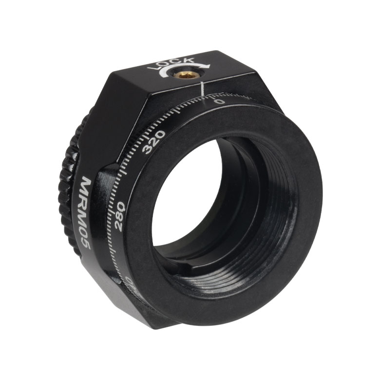 |  |  |  |  | 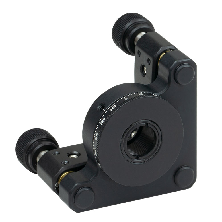 |  |
| Features | Mini Series | Standard | External SM1 (1.035"-40) Threads | Micrometer | 16 mm Cage-Compatible | ±4° Kinematic Tip/Tilt Adjustment Plus Rotation | Compatible with 30 mm Cage Translation Stages and 1/4" Translation Stagesb |
| Additional Details | |||||||
| Rotation Mounts for Ø1" Optics | ||||||||
|---|---|---|---|---|---|---|---|---|
| Item # | RSP1(/M) | LRM1 | RSP1D(/M) | DLM1(/M) | CLR1(/M) | RSP1X15(/M) | RSP1X225(/M) | PRM1(/M)a |
| Click Photo to Enlarge |  | 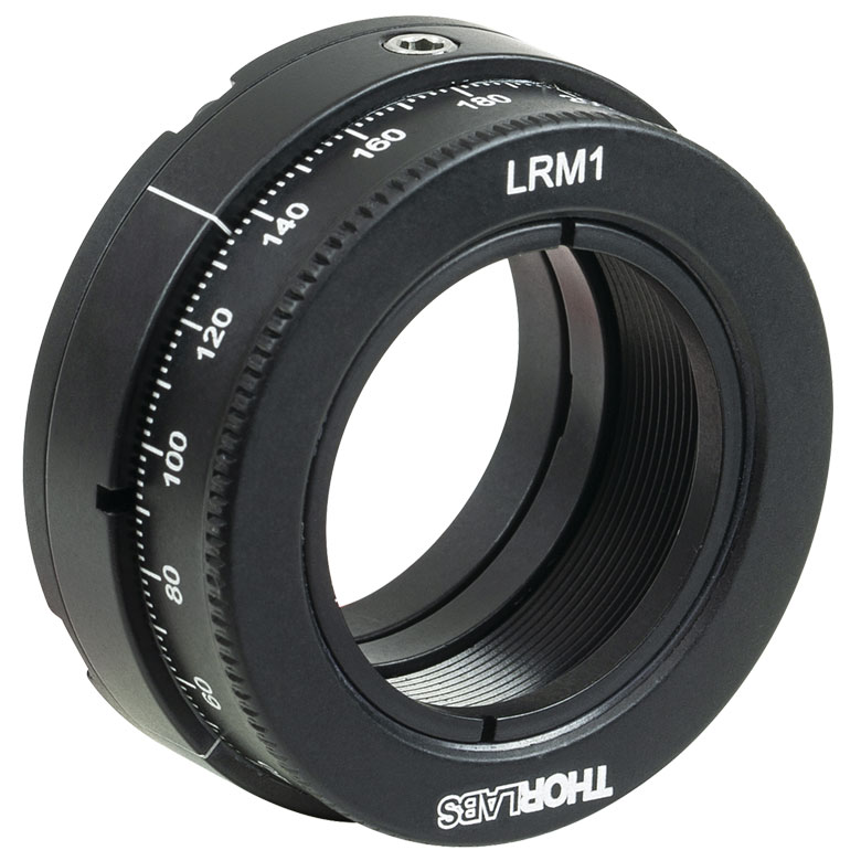 |  | 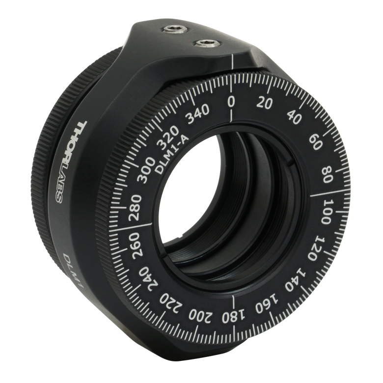 | 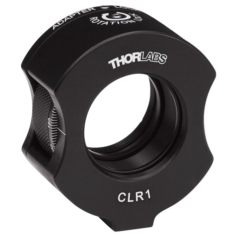 | 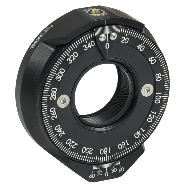 | | 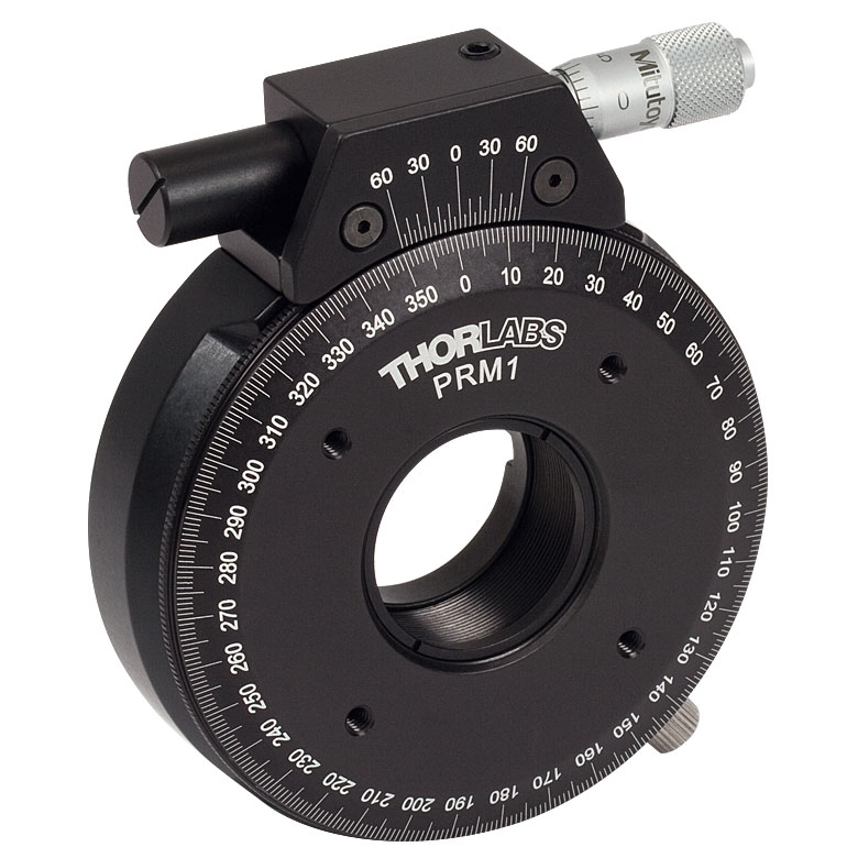 |
| Features | Standard | External SM1 (1.035"-40) Threads | Adjustable Zero | Two Independently Rotating Carriages | Rotates Optic Within Fixed Lens Tube System | Continuous 360° Rotation or 15° Increments | Continuous 360° Rotation or 22.5° Increments | Micrometer |
| Additional Details | ||||||||
| Rotation Mounts for Ø1" Optics | ||||||
|---|---|---|---|---|---|---|
| Item # | LM1-A & LM1-B(/M) | CRM1T(/M) | CRM1LT(/M) | CRM1PT(/M) | KS1RS | K6XS |
| Click Photo to Enlarge | 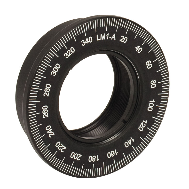 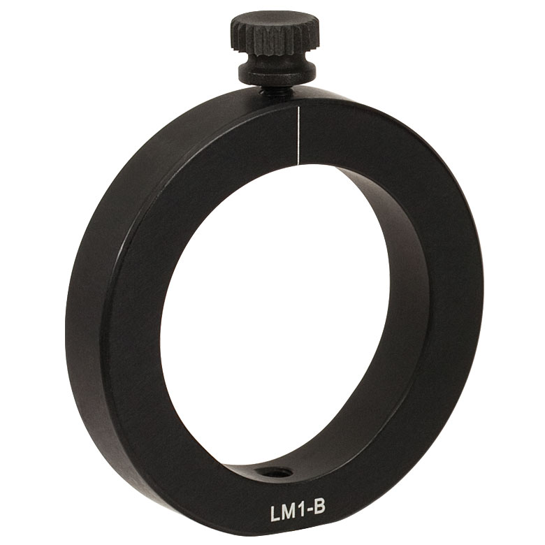 | 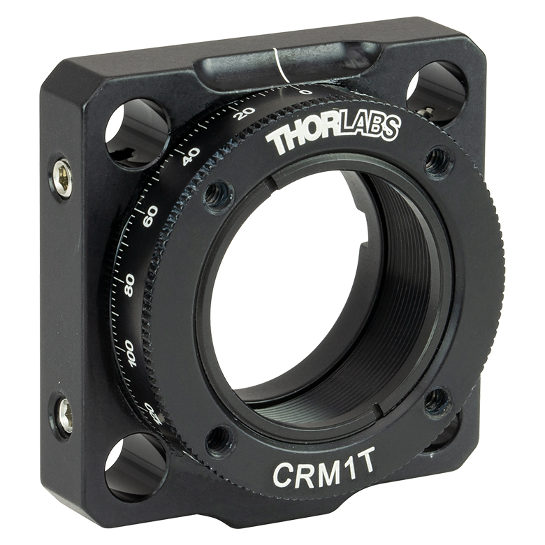 |  |  |  | 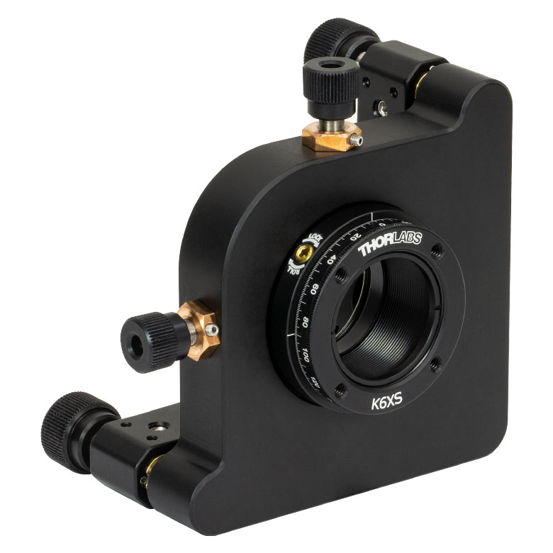 |
| Features | Optic Carriage Rotates Within Mounting Ring | 30 mm Cage-Compatiblea | 30 mm Cage-Compatible for Thick Opticsa | 30 mm Cage-Compatible with Micrometera | ±4° Kinematic Tip/Tilt Adjustment Plus Rotation | Six-Axis Kinematic Mounta |
| Additional Details | ||||||
| Rotation Mounts for Ø2" Optics | |||||||
|---|---|---|---|---|---|---|---|
| Item # | RSP2(/M) | RSP2D(/M) | PRM2(/M) | LM2-A & LM2-B(/M) | LCRM2A(/M) | KS2RS | K6X2 |
| Click Photo to Enlarge |  |  | 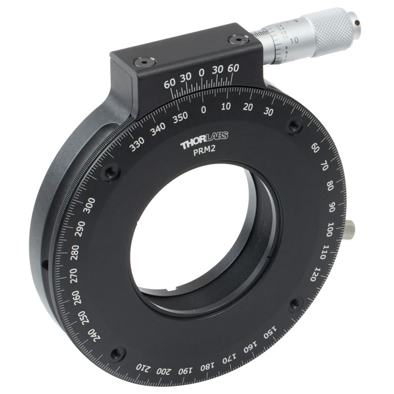 | 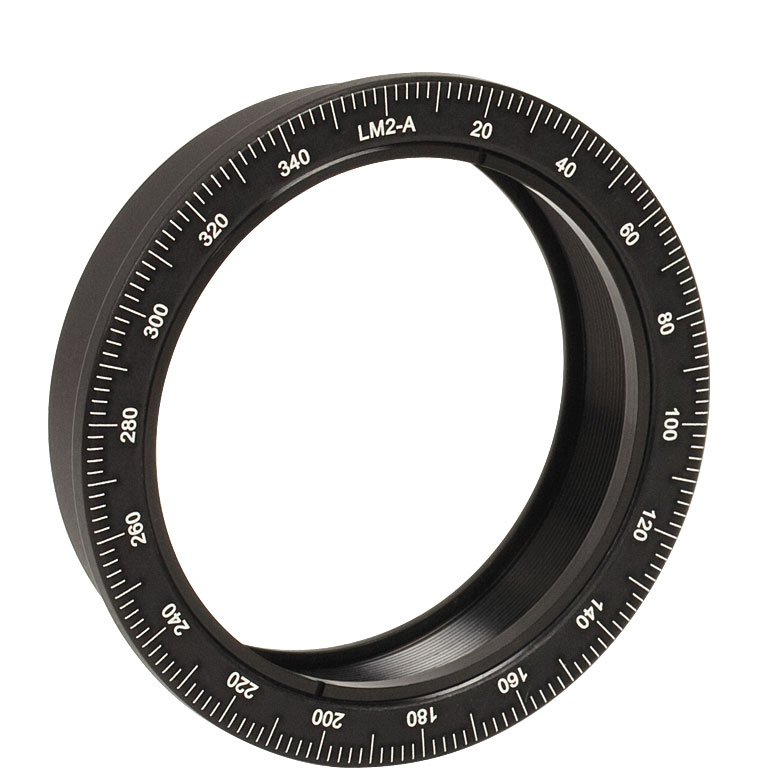 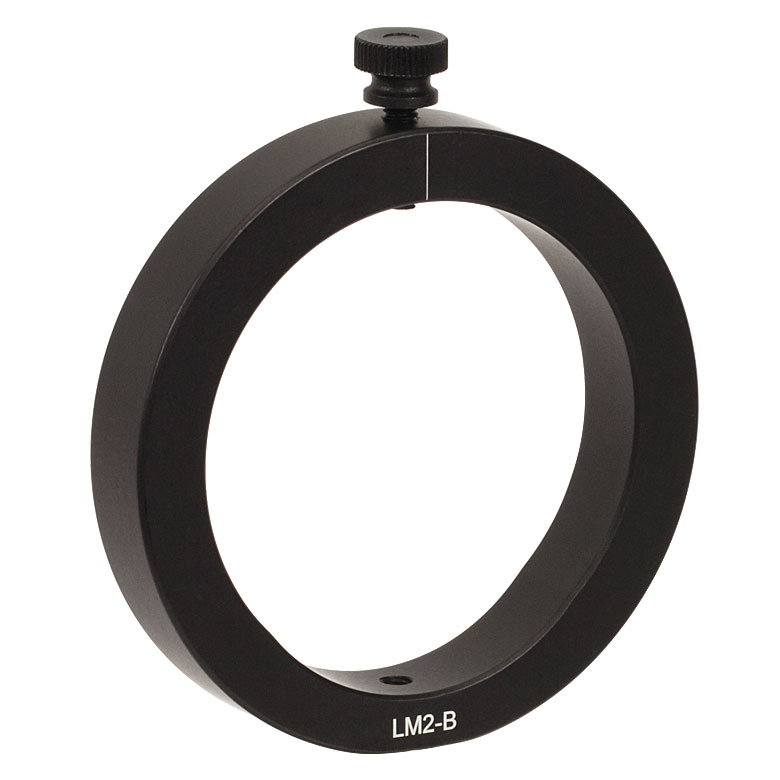 |  |  | 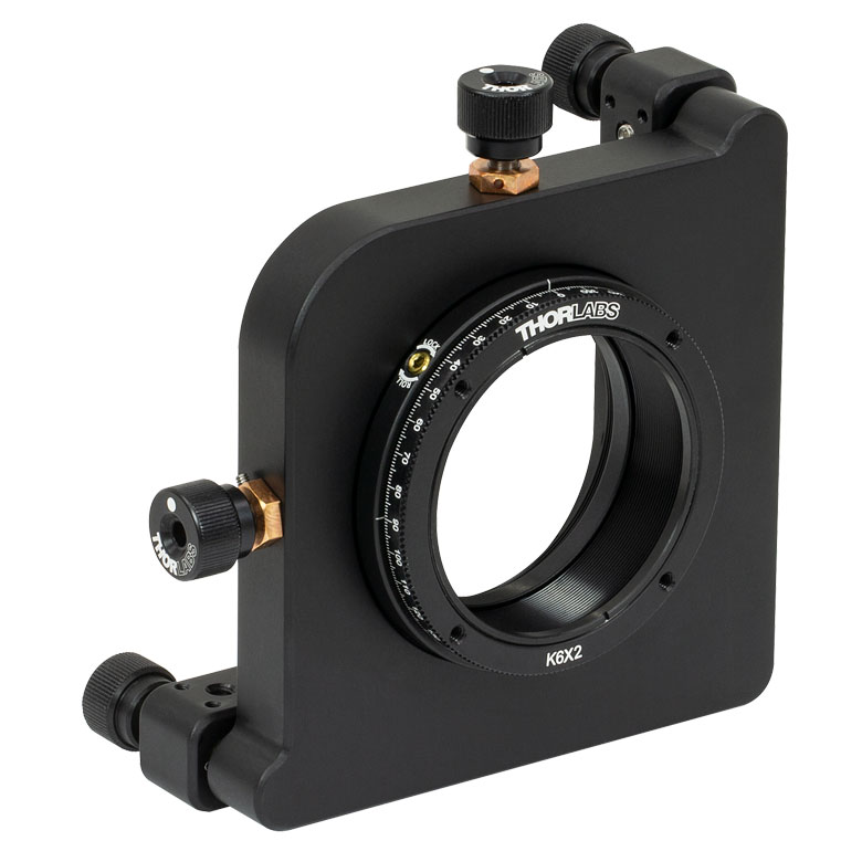 |
| Features | Standard | Adjustable Zero | Micrometer | Optic Carriage Rotates Within Mounting Ring | 60 mm Cage-Compatible | ±4° Kinematic Tip/Tilt Adjustment Plus Rotation | Six-Axis Kinematic Mount |
| Additional Details | |||||||
| Rotation Drive Mechanism and Adjustment Range | Manual, 360° Continuous | Coarse: Manual, 360° Continuous; Fine: ±7° Micrometer | Manual, 360° Continuous | ||||
| Optic Mounting | Internally SM2-Threaded Carriage | Internal SM2 Threads in LM2-A | Internally SM2-Threaded Carriage | ||||
| Maximum Accepted Optic Thickness | 0.51" (13 mm) | 0.54" (13.7 mm) | 0.48" (12.2 mm) | 0.46" (11.7 mm) | 0.52" (13.2 mm) | 0.47" (12 mm) | 0.53" (13.4 mm) |
| Post Mounting | 8-32 (M4) Tap | 8-32 (M4) Tap in LM2-B | 8-32 (M4) Tap | Four Counterbores for 8-32 (M4) Cap Screws | Six Counterbores for 8-32 (M4) Cap Screws | ||
| Cage System Compatibility | N/A | Four 4-40 (M3) Taps on Rotation Dial with 60 mm Spacing | N/A | Four Bores for Ø6 mm Cage Rods with 60 mm Spacing | N/A | N/A | |
手動回転ステージ
| Manual Rotation Stages | ||||||
|---|---|---|---|---|---|---|
| Item # | RP005(/M) | PR005(/M) | MSRP01(/M) | RP01(/M) | RP03(/M) | QRP02(/M) |
| Click Photo to Enlarge | 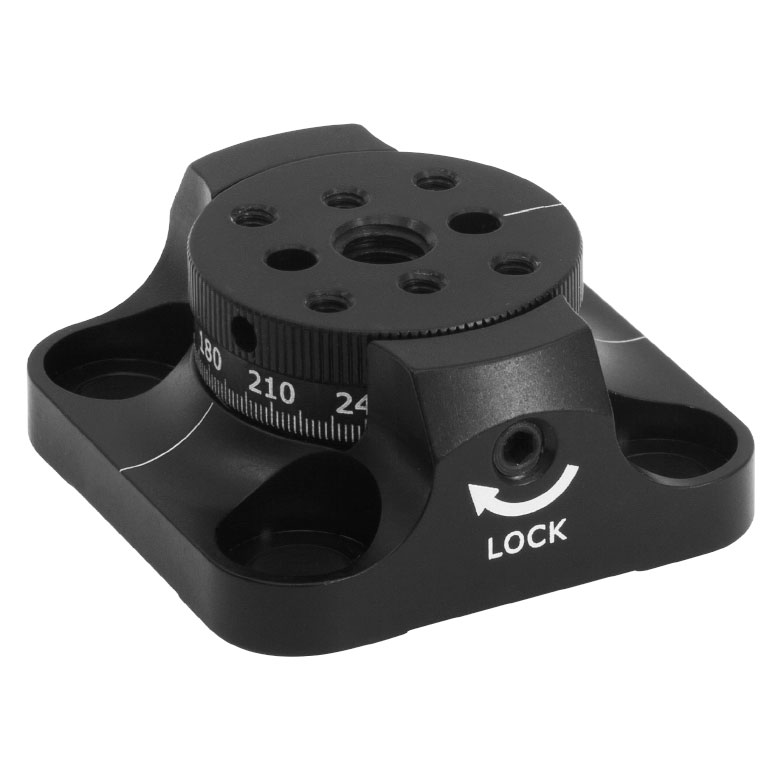 | 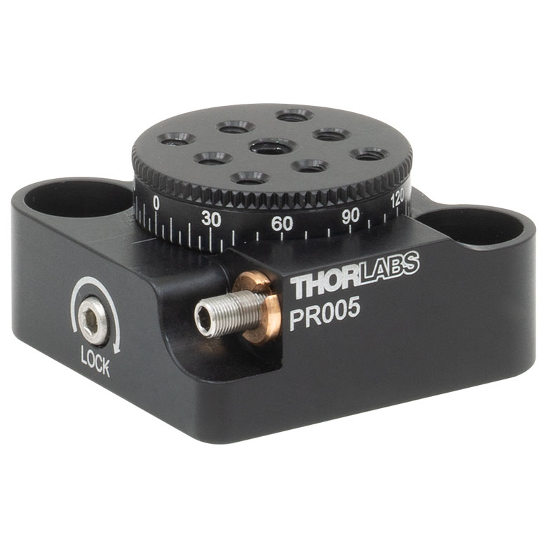 | 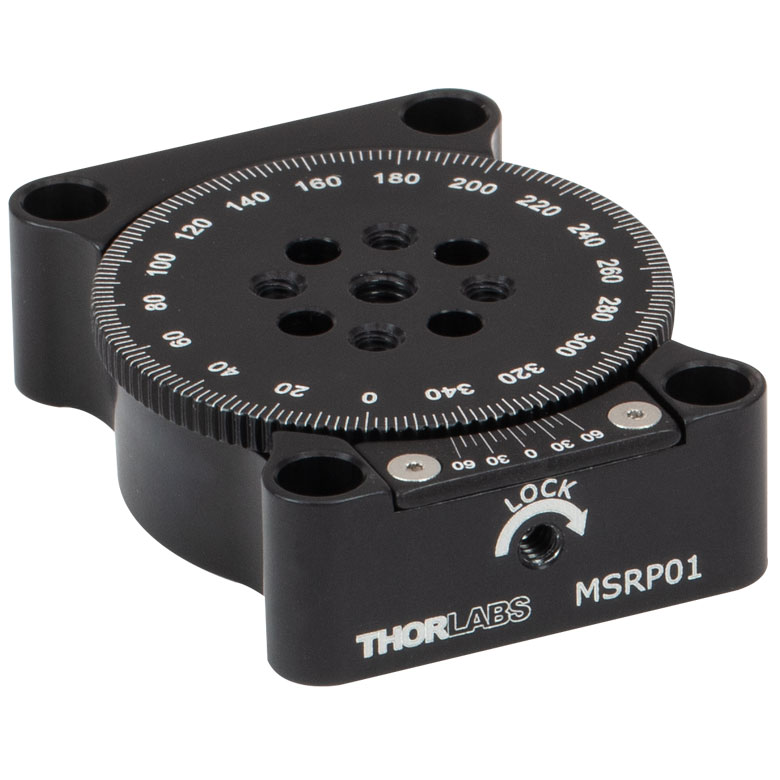 | 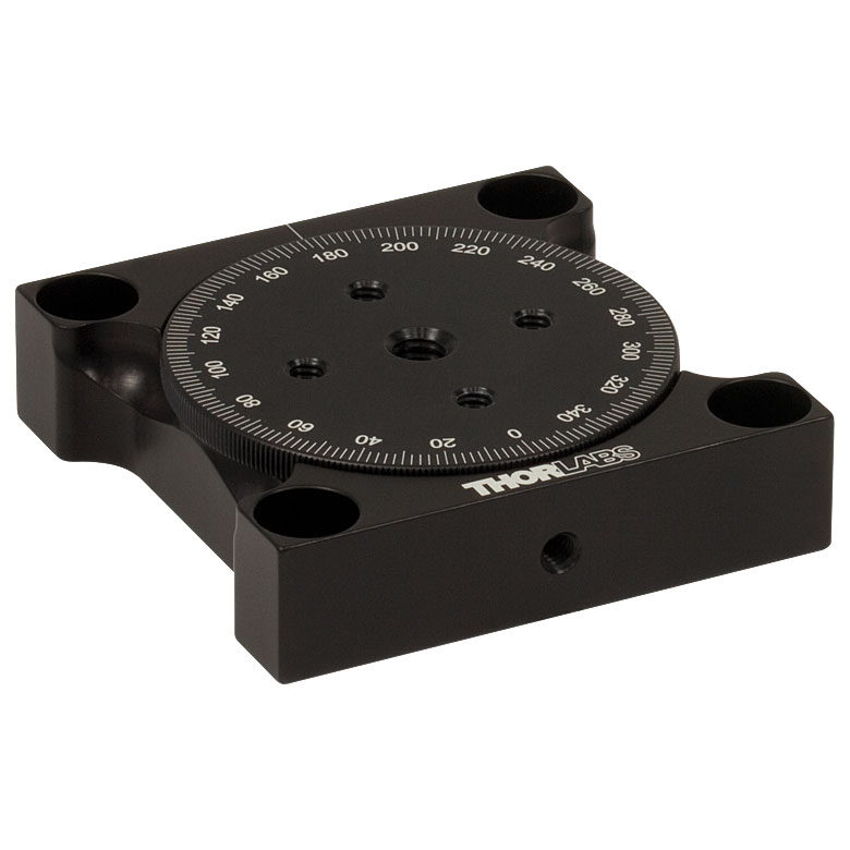 | 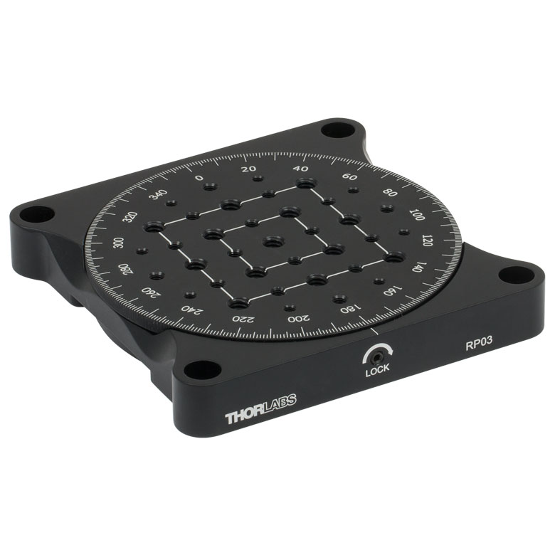 | 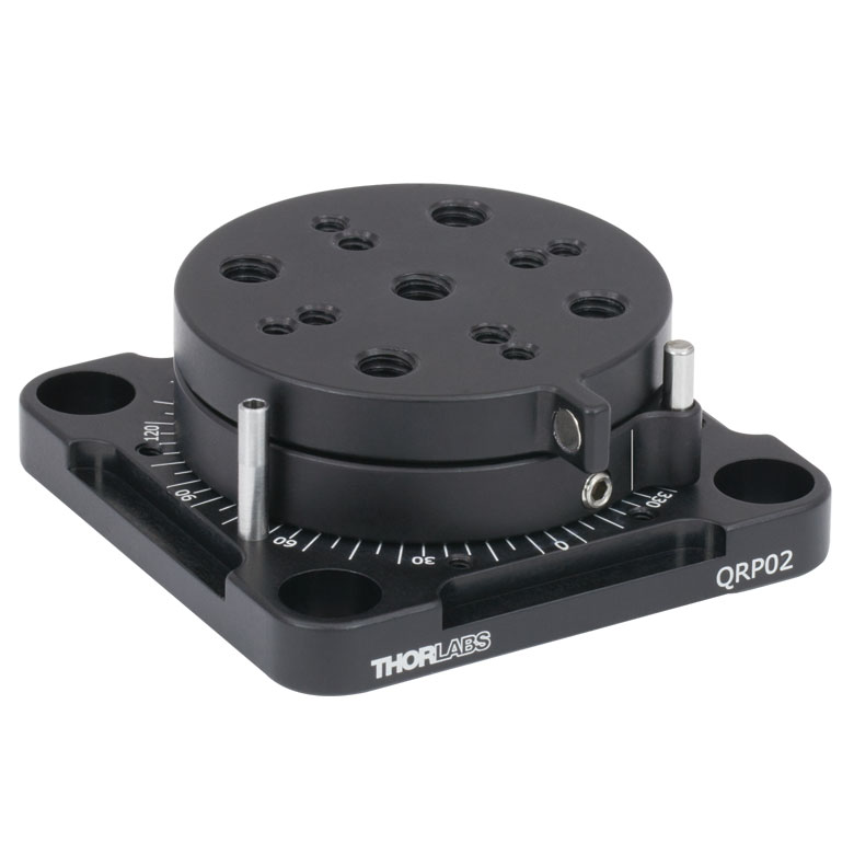 |
| Features | Standard | Two Hard Stops | ||||
| Additional Details | ||||||
| Manual Rotation Stages | ||||||
|---|---|---|---|---|---|---|
| Item # | XRNR1(/M) | XRR1(/M) | PR01(/M) | CR1(/M) | XYR1(/M) | OCT-XYR1(/M) |
| Click Photo to Enlarge | 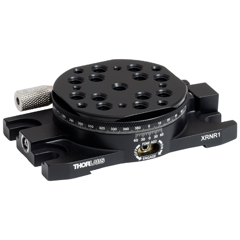 |  | 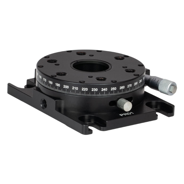 | 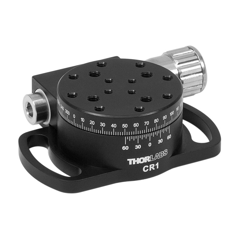 | 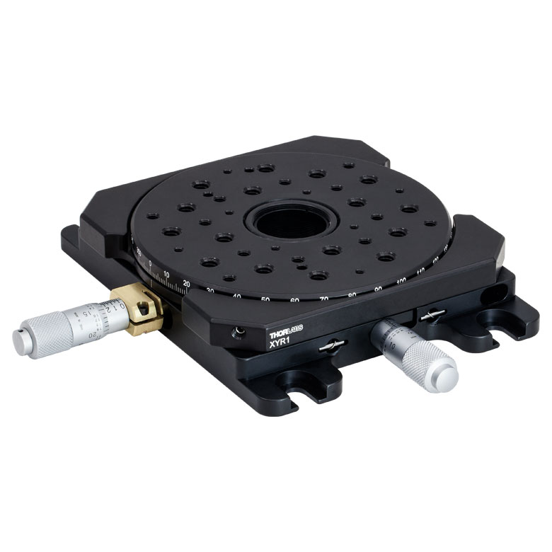 | 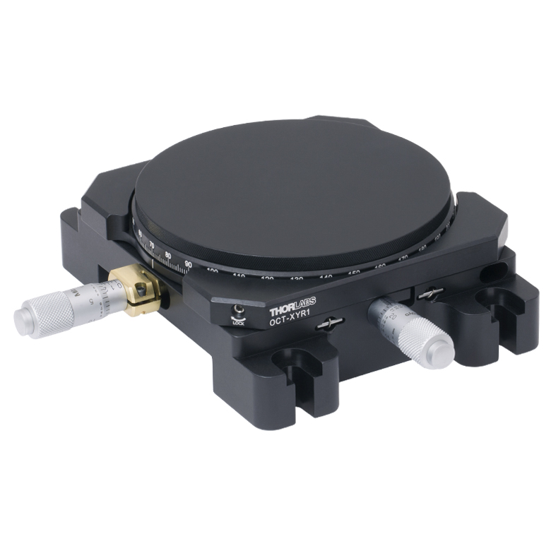 |
| Features | Fine Rotation Adjuster and 2" Wide Dovetail Quick Connect | Fine Rotation Adjuster and 3" Wide Dovetail Quick Connect | Fine Rotation Adjuster and SM1-Threaded Central Aperture | Fine Pitch Worm Gear | Rotation and 1/2" Linear XY Translation | |
| Additional Details | ||||||
電動回転マウント&ステージ
| Motorized Rotation Mounts and Stages with Central Clear Apertures | |||||
|---|---|---|---|---|---|
| Item # | DDR25(/M) | PDR1C(/M) | PDR1(/M) | PDR1V(/M) | PDXR1(/M) |
| Click Photo to Enlarge | 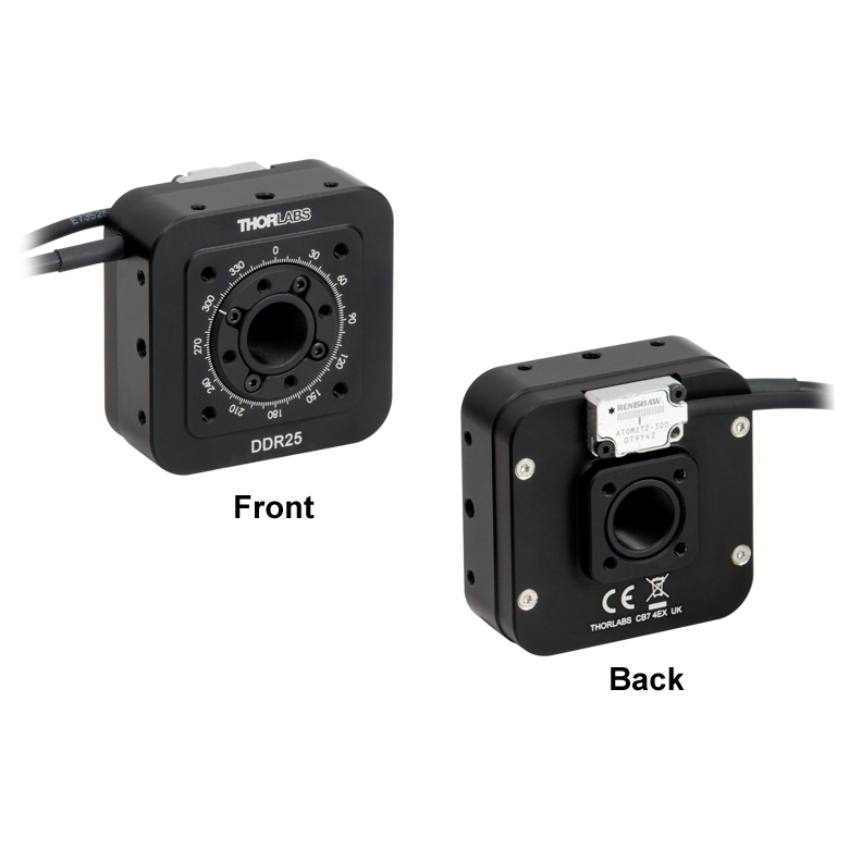 | 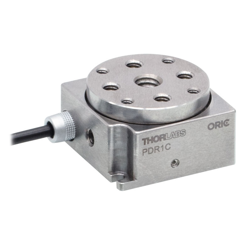 | 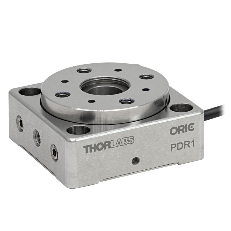 |  |  |
| Features | Compatible with SM05 Lens Tubes, 16 mm Cage System, & 30 mm Cage System | Compatible with 16 mm Cage System | Compatible with SM05 Lens Tubes & 30 mm Cage System | Vacuum-Compatible; Also Compatible with SM05 Lens Tubes & 30 mm Cage System | Compatible with SM05 Lens Tubes & 30 mm Cage System |
| Additional Details | |||||
| Motorized Rotation Mounts and Stages with Central Clear Apertures | |||||||
|---|---|---|---|---|---|---|---|
| Item # | K10CR1(/M) | PRM1Z8(/M)a | DDR100(/M) | ELL16 | ELL14 | ELL21(/M) | HDR50(/M) |
| Click Photo to Enlarge | 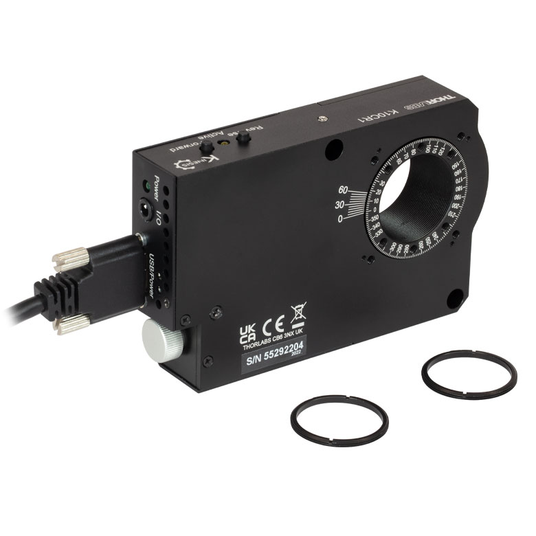 | 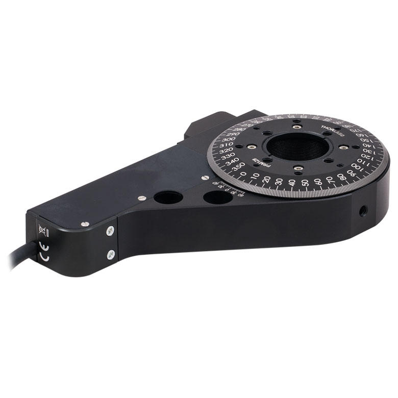 | 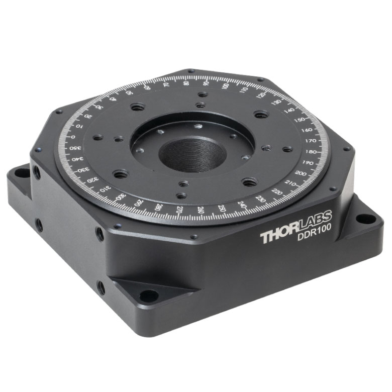 |  | 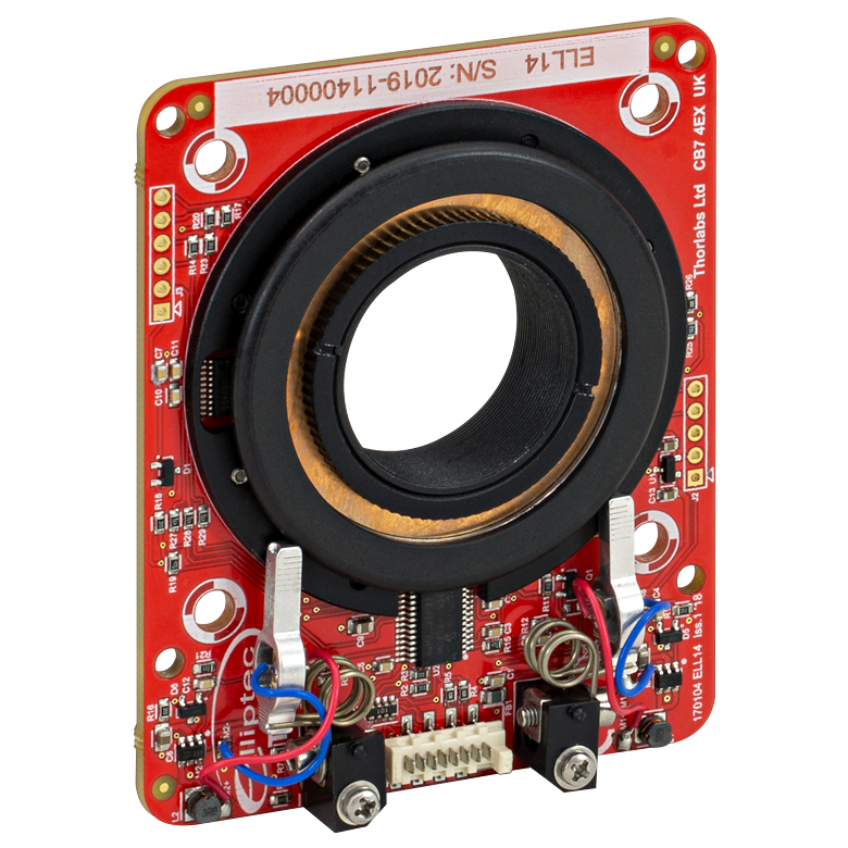 | 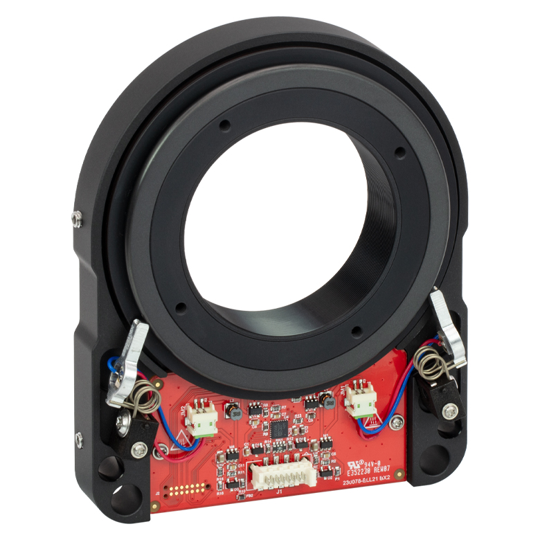 | 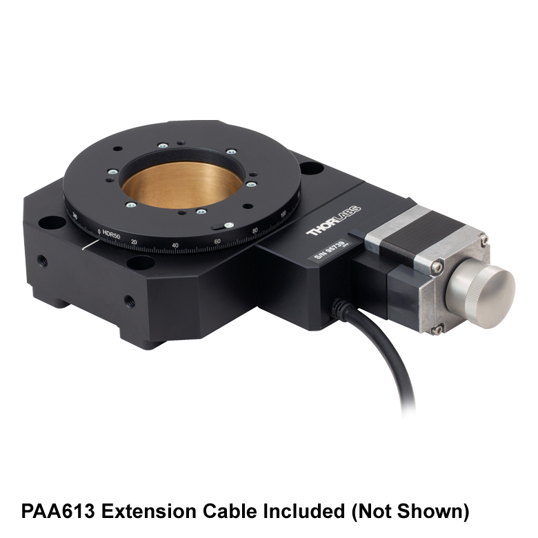 |
| Features | Compatible with SM1 Lens Tubes & 30 mm Cage System | Compatible with SM1 Lens Tubes, 16 mm Cage System, 30 mm Cage System | Compatible with SM05 Lens Tubes, Open Frame Design for OEM Applications | Compatible with SM1 Lens Tubes, Open Frame Design for OEM Applications | Compatible with SM2 Lens Tubes, Open Frame Design for OEM Applications | Compatible with SM2 Lens Tubes | |
| Additional Details | |||||||
| Motorized Rotation Mounts and Stages with Tapped Platforms | ||
|---|---|---|
| Item # | PRMTZ8(/M)a | ELL18(/M)b |
| Click Photo to Enlarge | 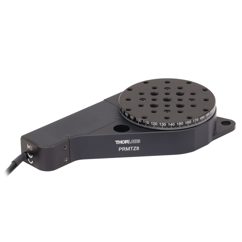 | 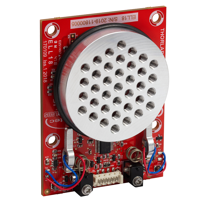 |
| Features | Tapped Mounting Platform for Mounting Prisms or Other Optics | Tapped Mounting Platform, Open Frame Design for OEM Applications |
| Additional Details | ||

 ズーム
ズーム
Click for Details
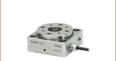
Figure G1.1 HDR50(/M)の回転部の概略図
- 回転部および非回転部の中心にはSM2ネジの付いた開口
- 部品や上部プレート用アダプタを取り付けるためのM4タップ穴
- 取り付け部の特長
- 4つのM6皿穴
- 4つの取付け用M6タップ穴(側面に2つずつ)
- 長さ3 mのエクステンションケーブルPAA613が付属
高耐荷重回転ステージHDR50/Mの回転部および非回転部の中央にはSM2ネジの付いた開口があります(Figure G1.1参照)。ネジの深さは回転部では6.9 mm、下側の非回転部では4.0 mmです。上記の上部プレート用アダプタを使用すれば、これ以外にも取付けオプションが広がります。これらのアダプタは、ステージの回転部にあるM4タップ穴を用いて取り付けます。
ステージHDR50/Mは、長さ35 mm以上のM6キャップスクリュ(付属しません)を用いてブレッドボードに直接取り付けることができます。また、側面にある穴または上記のブラケットNR360SP2/Mを用いて垂直方向に取り付けることもできます。さらにアダプタNR360SP5/Mを使用すれば、LNR50シリーズまたはNRTシリーズの移動ステージにも取り付けられます。

 ズーム
ズーム
Click for Details
Figure G2.3 アダプタNR360SP4(/M)
Click for Details
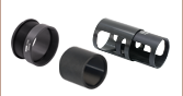
Figure G2.2 アダプタNR360SP8
Click for Details
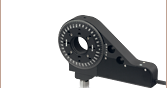
Figure G2.1 アダプタNR360SP9(/M)
- 上部プレート用アダプタはM4ザグリ穴を用いて取り付け
- アダプタNR360SP9/MにはM6タップ穴が17個
- アダプタNR360SP8:
- Ø25 mm~Ø25.4 mm(Ø1インチ)レンズチューブ用のSM1ネジ付き穴
- 30 mmケージシステム用の#4-40取付け穴
- 1/4"-20および#8-32取付け穴がそれぞれ4つ
- アダプタNR360SP4/Mにはファイバーアライメントアクセサリのための幅3 mmのアライメント用溝
こちらの上部プレート用アダプタを用いることで、回転ステージHDR50/Mの取付けオプションが広がります。アダプタは付属の4本のM4ネジを用いてステージ上部の可動部に取り付けます。ミリ規格のアダプタにはミリ規格のネジが付属し、インチ規格のアダプタにはインチ規格のネジが付属しますが、アダプタ本体はどちらの規格のステージにも対応します。例えば、4本のM4ネジを使用すれば、インチ規格のアダプタをミリ規格のステージに取り付けることができます。これらのアダプタは、旧製品のステージNR360S/Mにも対応しています。
可動部には、取付け用として様々なネジ穴や通し穴を有する、別売りのアダプタープレートELLA6/M、ELLA7/M、およびELLA8を取り付けることも可能です。アダプタELLA6/Mには30 mmケージシステム用に配置された取付け穴があり、またファイバーアクセサリ取付け用の3 mmキー溝があります。ELLA7/Mにも同様の取付け穴があり、30 mmケージシステムの取付けが可能ですが、そのほかに中央にSM1内ネジ付きの穴があります。アダプタELLA8には5つのSM05内ネジ付きポートがあり、マウント付きのフィルタや光学素子の取付けにご使用いただけます。また中央にはØ12.7 mm(Ø1/2インチ)の穴が開いています。

 ズーム
ズーム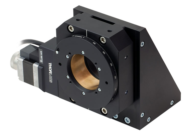
Click to Enlarge
Figure G3.1 ブラケットNR360SP2(/M)に垂直に取り付けられたステージHDR50(/M)
- 回転ステージHDR50/Mの垂直取付け用
- SM2レンズチューブに対応するØ68.0 mmの貫通穴
- ベース部分にはブレッドボード取付け用のM6ザグリ穴が7つ
- 取付け用ネジは付属しません。
垂直取付けブラケットNR360SP2/Mを使用して、ステージHDR50/Mまたは旧製品のステージNR360S/Mを垂直方向に取り付けることができます。Ø68.0 mmの穴は、ステージ底部に取り付けられたSM2レンズチューブを貫通させることができます。また、ブラケットは7つのM6ザグリ穴を用いて光学テーブルまたは光学ブレッドボードに固定できます。ステージHDR50/Mをブラケットに取り付ける際に、長さ35 mm以上の4本のM6キャップスクリュ(付属しません)が必要です。

 ズーム
ズーム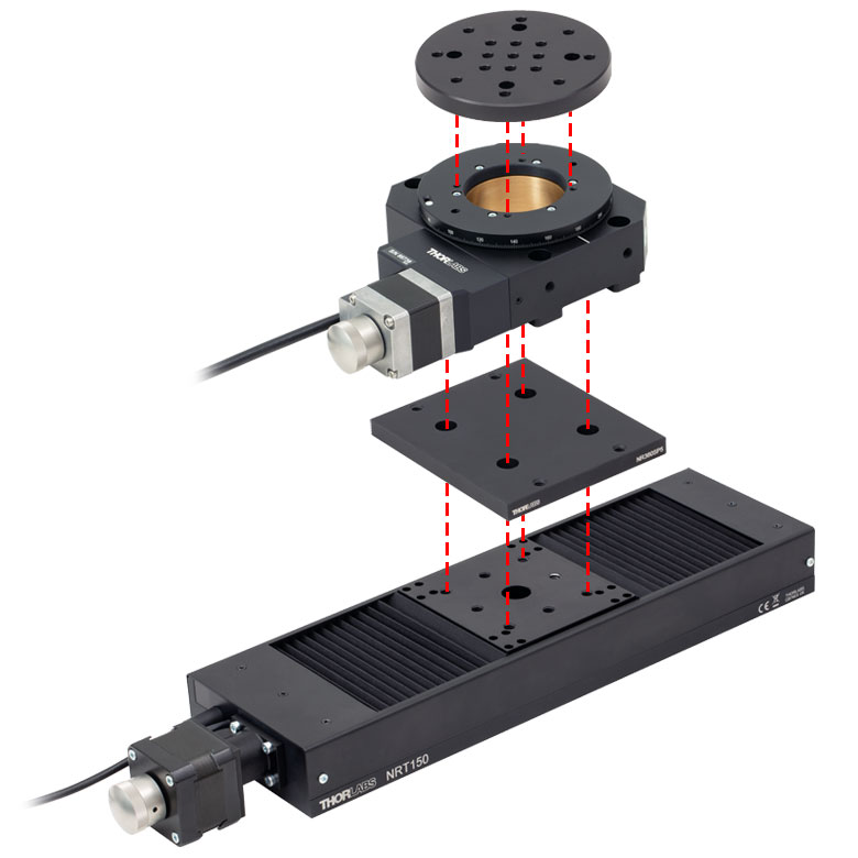
Click for Details
Figure G4.1 取付けアダプタNR360SP5(/M)付き回転ステージHDR50(/M)をアダプタープレートNR360SP9(/M)を使用して移動ステージNRT150(/M)に取り付け
取付けアダプタNR360SP5/Mを使用して、ステージHDR50/Mまたは旧製品のステージNR360S/Mを、LNR50シリーズのステージや、ステージNRT100/MまたはステージNRT150/Mの上部に取り付けることができます(Figure G4.1真参照)。取付けには、長さ10 mmのM6 キャップスクリュ(4本)、および長さ35 mmのM6キャップスクリュ(4本)が必要です(どちらも付属しません)。