光ファイバ用高速ディテクタ
- Sensitive to Wavelengths from 400 - 1700 nm
- Bandwidths from 1 to 5 GHz
- Rise Times as Short as 50 ps
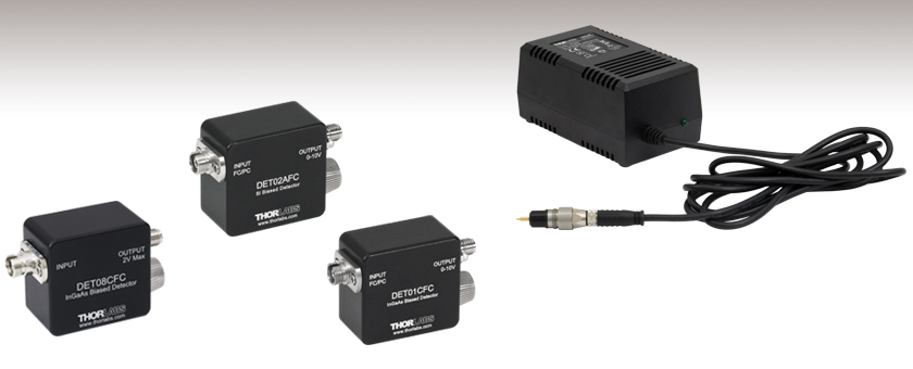
DET08CFC
DET02AFC
DET01CFC
DET2B
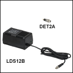
Replaces the battery in our DET series detectors and includes the LDS12B power supply and DET2A power adapter, shown connected.

Please Wait
特長
- 4つのモデルで400~1700 nmの波長範囲に対応
- 帯域幅:1~5 GHz
- 立ち上がり時間(Rise Time):50 ps~1 ns
- シングルモード(SM)またはマルチモード(MM)ファイバに接続
- FC/PCファイバ入射用コネクタ
- SMA出力コネクタ
当社ではFC/PCコネクタの入力端子のあるシングルモードまたはマルチモードファイバ、高速・高い帯域の光ファイバーフォトディテクタを多岐にわたってご用意しております。 全てのモデルのディテクタがカバーする波長範囲は可視域から近赤外域(400~1700 nm)にわたります。各ディテクタが対応する詳しいスペクトル範囲については、右のセレクションガイドの表をご参照ください。 このページに掲載されているディテクタはすべてGHzレベルの信号帯域に対応し、当社の他のDETシリーズ同様の使いやすさが特長です。 データ通信、アナログマイクロ波や一般的な高速フォトニクス研究を含む、高速の光信号を扱う試験や測定の用途を想定して設計されています。 自由空間での同様の検出用途には、高速自由空間用ディテクタをご用意しています。 また、動作速度はこれらのディテクタより遅くなりますが、ファイバ入力型フォトディテクタと同等の使いやすさを備えたバイアス型フォトディテクタも種類豊富に取り揃えています。当社のバイアスディテクタはベンチトップ型フォトダイオード増幅器およびPMTトランスインピーダンスアンプとお使いいただけます。
これらのファイバ入力ディテクタは、逆バイアスで、またバイアス電池を内蔵しており、入力される入射光に対して線形の応答性を示します。 高い帯域の出力の信号に対応するために、信号はSMAコネクタから出力されます。 当社では多岐にわたる電気アダプタやケーブル(SMAケーブルやSMA-BNC変換アダプタなど)をご用意しており、オシロスコープやその他の電子計測機器と共に用いることで出力信号がモニタできます。
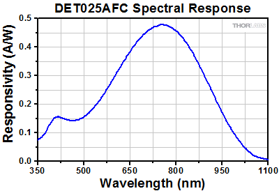
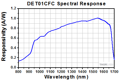
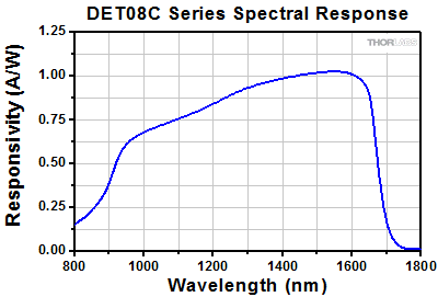
シリコン(Si)ベースのファイバ入力ディテクタは、400~1100 nmの波長範囲に対応して、帯域幅はそれぞれ1 GHz(型番 DET02AFC/M)と2 GHz(型番 DET025AFC/M)になっています。 近赤外域の波長範囲を含む用途では、InGaAsベースのファイバ入力ディテクタが適します。このタイプでは、800~1700 nm(型番 DET01CFC/M)、850~1700 nm(型番 DET08CFC/M)の波長範囲に対応して、帯域幅はそれぞれ1.2 GHz、5 GHz(Max)です。 高速の信号を調べる際には、50 Ωの負荷抵抗器をご使用いただくことをお勧めしています。 低い帯域の用途では、可変ターミネータまたは固定型スタブターミネータをお使いいただくと測定電圧の迅速な調整が可能です。
このページでご紹介するすべてのディテクタには、ノイズが非常に低い12 VDCバイアス電池 A23が付属しています。 AC入力電圧の雑音に起因する小さな信号雑音の上昇が許容される用途や、バッテリの寿命が問題となる用途でディテクタを使用する場合、このバッテリの代わりに電源アダプターセットDET2B(下記参照)をお使いいただくことも可能です。 メーカによって正極にわずかに物理的なバラツキがありますので、当社のDETシリーズフォトディテクタにはEnergizer®のバッテリの使用をお勧めしています。
| Item # | DET02AFC | DET025AFC | DET01CFC | DET08CFC |
|---|---|---|---|---|
| Wavelength Range | 400 - 1100 nm | 400 - 1100 nm | 800 - 1700 nm | 800 - 1700 nm |
| Material | Si | Si | InGaAs | InGaAs |
| Bandwidth (-3 dB)a,b,c | 1 GHz | 2 GHz | 1.2 GHz | 5 GHz (Max) |
| Fiber Input | FC/PC | FC/PC | FC/PCd | FC/PC |
| Signal Output | SMA | SMA | SMA | SMA |
| Minimum Resistor Load | 50 Ω | 50 Ω | 50 Ω | 50 Ω |
| Maximum Peak Power | 18 mW | 18 mW | 18 mW | 100 mW |
| Saturation Power (CW) | - | - | 5.5 mW (1550 nm)b | - |
| Output Voltage | 0 to 3.3 V (50 Ω) 0 to 10 V (Hi-Z) | 2 V (Max)e | 0 to 1 V (50 Ω)f 0 to 10 V (Hi-Z) | 2 V (Max)e |
| Rise Time (tr)a,b,c | 1 ns @ 730 nm (Max) | 150 ps @ 653 nm, 20/80% (Typ.) | < 1 nsg @ 1310 nm | 70 ps @ 952 nm, 20/80% (Typ.) |
| Fall Time (tf)a,b,c | 1 ns @ 730 nm (Max) | 150 ps @ 653 nm, 80/20% (Typ.) | < 1 nsg @ 1310 nm | 110 ps @ 952 nm, 80/20% (Typ.) |
| Bias Voltage | 12 V | |||
| Dark Current | 126 pAh | 35 pAa,h | 0.235 nAa,h | 1.5 nAa,h |
| NEP (Maximum) | 9.5 x 10⁻¹⁵ W/√Hz (@ 730 nm) | 9.29 x 10⁻¹⁵ W/√Hz (@ 730 nm) | 4.5 x 10⁻¹⁵ W/√Hz (@ 1550 nm) | 2 x 10-15 W/√Hz (@ 1550 nm) |
| Junction Capacitance | 1.73 pF (Max) | 1.73 pF (Max) | 2.4 pF (Typical) | 0.3 pF |
| Photodiode Element | FDS02 | FDS02 | FGA01FC | - |
信号出力端子
SMAメス型
0~10 V w/ 50 Ω
電池の寿命
電池駆動のフォトディテクタを使う場合には、電池の寿命とそれがディテクタの駆動に与える影響を理解することが重要です。電流出力デバイスとして、フォトディテクタの出力電流は、ディテクタに入射する光に比例します。殆どの場合、終端抵抗を用いてこの電流を電圧へと変換します。抵抗値は回路の利得とほぼ等しくなります。高速ディテクタでは、標準同軸ケーブルのインピーダンスを整合してケーブルの反射を減らし、全体的な信号の性能を向上させるために50 Ω終端抵抗を使うことが大切です。多くの広帯域オシロスコープには、この終端抵抗が装備されています。
電池の使用寿命は、ディテクタによって使われる電流に直接関連します。多くの電池製造メーカは、mA hrで電池寿命を示しています。例えば、ディテクタDET08CFCに付属の電池は40 mA hrsです。これは、1.0 mAの電流で40時間動作することを意味します。この電池を例として用い、以下に、使用方法による電池寿命の算定方法について説明します。
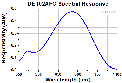
この例では、平均光出力1 mWで波長780 nmの光源をディテクタDET08CFCに入力しています。この波長での感度曲線に基づいたバイアス型フォトディテクタの感度は、0.5 A/Wとなります。光電流は次のように計算されます。

電池の定格寿命が40 mA hrの場合、電池の寿命は次のようになります。

あるいは、3.3日の連続使用となります。平均入射光を10 µWまで減らすと、同じ電池は連続使用で約333日もちます。推奨の50 Ω終端抵抗を使うと、光電流0.5 mAは次の電圧に変換されます。

入射パワーレベルを10 µWまで減らすと、出力電圧は0.25 mVになります。いくつかの測定装置では、この信号レベルは低すぎるので、電池寿命と測定精度の間で妥協を行なう必要があります。
バイアス型フォトディテクタを電池で駆動する場合、最小電圧レベルが必要であることを念頭において、できるだけ低い光強度を使うことが望ましいです。また、電池は寿命が近づいても、すぐに電流が止まるわけではありません。その代わり、電池の電圧が下がり、そして、フォトダイオードに印加されている電圧は減少します。これにより、ディテクタの応答時間が長くなります(ディテクタの帯域幅が小さくなります)。従って、バイアス型フォトディテクタを適切に機能させるために、電池を特定のパラメータ内で動作させることが重要です。電圧はマルチメータで確認いただくことが可能です。
また、センサに入射している光を取り除いたり、出力を弱めたりすることでも電池の寿命は延びます。光源がないと、フォトディテクタは暗電流に比例した電流を消費しますが、この電流は微小です。例えば、DET08CFCでは、1.5 nA以下の暗電流です。
DETシリーズのフォトダイオードが連続して比較的高パワーの光を照射される場合や電池を変えられない場合、電源アダプターセットDET2B(電源アダプタおよび電源のセット、下記掲載)をお使いください。このオプションの欠点は、AC電源電圧の雑音が出力信号の雑音に加わり、測定がより不確かになる可能性があるということです。
フォトダイオードのチュートリアル
動作原理
接合型フォトダイオードは、通常の信号ダイオードと似た動作をする部品ですが、接合半導体の空乏層が光を吸収すると、光電流を生成する性質があります。フォトダイオードは、高速なリニアデバイスで、高い量子効率を達成し、様々な用途で利用することが可能です。
入射光の強度に応じた、出力電流レベルと受光感度を正確に把握することが必要とされます。Figure 100Aは、接合型フォトダイオードのモデル図で、基本的な部品要素が図示されており、フォトダイオードの動作原理が説明されています。

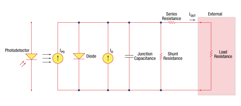
Figure 100A フォトダイオードの概略図
フォトダイオード関連用語
受光感度
フォトダイオードの受光感度は、規定の波長における、生成光電流 (IPD)と入射光パワー(P)の比であると定義できます。

Photoconductiveモード(光導電モード)とPhotovoltaicモード(光起電力モード)
フォトダイオードは、Photoconductiveモード(逆バイアス) またはPhotovoltaicモード(ゼロバイアス)で動作できます。 モードの選択は、使用用途で求められる速度と、許容される暗電流(漏れ電流)の量で決まります。
Photoconductiveモード(光導電モード)
Photoconductiveモードでは、逆バイアスが印加されますが、これが当社のDETシリーズディテクタの基本です。回路で測定できる電流量はフォトダイオードに照射される光の量を反映します。つまり、測定される出力電流は、入射される光パワーに対しリニアに比例します。逆バイアスを印加すると、空乏層を広げて反応領域が広くなるため、接合容量が小さくなり、良好な線形応答が得られます。このような動作条件下では、暗電流が大きくなりがちですが、フォトダイオードの種類を選ぶことで、暗電流を低減することもできます。(注:当社のDETディテクタは逆バイアスで、順方向バイアスでは動作できません。)
Photovoltaicモード(光起電力モード)
Photovoltaicモードでは、フォトダイオードはゼロバイアスで使用されます。デバイスからの電流の流れが制限されると電位が上昇します。このモードでは光起電力効果が引き起こされますが、これが太陽電池の基本です。Photovoltaicモードでは、暗電流は小さくなります。
暗電流
暗電流とは、フォトダイオードにバイアス電圧が付加されている時に流れる漏れ電流です。Photoconductiveモードで使用する場合に暗電流の値は高くなりがちで、温度の影響も受けます。 暗電流は、温度が10°C上昇するごとに約2倍となり、シャント抵抗は6°C の上昇に伴い倍になります。高いバイアスを付加すれば、接合容量は小さくなりますが、暗電流の量は増大してしまいます。
暗電流の量はフォトダイオードの材料や検出部の寸法によっても左右されます。ゲルマニウム製のデバイスでは暗電流は高くなり、それと比較するとシリコン製のデバイスは一般的には低い暗電流となります。Table 100Bではいくつかのフォトダイオードに使用される材料の暗電流の量と共に、速度、感度とコストを比較しています。
| Table 100B Photodiode Materials | ||||
|---|---|---|---|---|
| Material | Dark Current | Speed | Spectral Range | Cost |
| Silicon (Si) | Low | High Speed | Visible to NIR | Low |
| Black Silicon (B-Si) | Low | Medium Speeda | Visible to NIR | Moderate |
| Germanium (Ge) | High | Low Speed | NIR | Low |
| Indium Gallium Arsenide (InGaAs) | Low | High Speed | NIR | Moderate |
| Indium Arsenide Antimonide (InAsSb) | High | Low Speed | NIR to MIR | High |
| Extended Range Indium Gallium Arsenide (InGaAs) | High | High Speed | NIR | High |
| Mercury Cadmium Telluride (MCT, HgCdTe) | High | Low Speed | NIR to MIR | High |
接合容量
接合容量(Cj)は、フォトダイオードの帯域幅と応答特性に大きな影響を与えるので、フォトダイオードの重要な特性となります。ダイオードの面積が大きいと、接合容量が大きくなり、電荷容量は大きくなります。逆バイアスの用途では、接合部の空乏層が大きくなるので、接合容量が小さくなり、応答速度が速くなります。
帯域幅と応答性
負荷抵抗とフォトディテクタの接合容量により帯域幅が制限されます。最善の周波数応答を得るには、50 Ωの終端装置を50 Ωの同軸ケーブルと併用します。接合容量(Cj)と負荷抵抗値(RLOAD)により、帯域幅(fBW)と立ち上がり時間応答(tr)の概算値が得られます。

雑音等価電力
雑音等価電力(NEP:Noise Equivalent Power)とは、出力帯域幅1 Hzでの信号対雑音比(SNR)が1になる入力信号のパワーです。NEPによって、ディテクタが低レベルの光を検知する能力を知ることができるので、この数値は便利です。一般には、NEPはディテクタの検出部の面積増加に伴って大きくなり、下記の数式で求めることができます。

この数式において、S/Nは信号対雑音比、Δf はノイズの帯域幅で、入射エネルギ単位はW/cm2となっています。詳細は、当社のホワイトペーパー「NEP – Noise Equivalent Power」をご覧ください。
終端抵抗
オシロスコープでの測定を可能にするためには、生成された光電流を電圧(VOUT)に変換する必要がありますが、負荷抵抗を用いて電圧変換します。

フォトダイオードの種類によっては、負荷抵抗が応答速度に影響を与える場合があります。最大帯域幅を得るには、50 Ωの同軸ケーブルを使用して、ケーブルの反対側の終端部で50 Ωの終端抵抗器の使用を推奨しています。このようにすることで、ケーブルの特性インピーダンスとマッチングできて共鳴が最小化できます。帯域幅が重要ではない特性の場合は、RLOADを増大させることで、所定の光レベルに対して電圧を大きくすることができます。終端部が不整合の場合、同軸ケーブルの長さが応答特性に対して大きな影響を与えます。したがってケーブルはできるだけ短くしておくことが推奨されます。
シャント抵抗
シャント抵抗は、ゼロバイアスフォトダイオード接合の抵抗を表します。理想的なフォトダイオードでは、シャント抵抗は無限大となりますが、実際の数値はフォトダイオードの材料の種類によって、10Ωのレベルから 数千MΩの範囲となる場合があります。例えばInGaAsディテクタのシャント抵抗は、10 MΩのレベルですが、GeディテクタはkΩのレベルです。このことは、フォトダイオードのノイズ電流に大きく影響を与える可能性があります。しかしながらほとんどの用途では、ある程度高い抵抗値であればその影響は小さく、無視できる程度です。
直列抵抗
直列抵抗は半導体材料の抵抗値で、この低い抵抗値は、通常は無視できる程度です。直列抵抗は、フォトダイオードの接触接続部とワイヤ接続部で発生し、ゼロバイアスの条件下でのフォトダイオードのリニアリティの主な決定要因になります。
一般的な動作回路
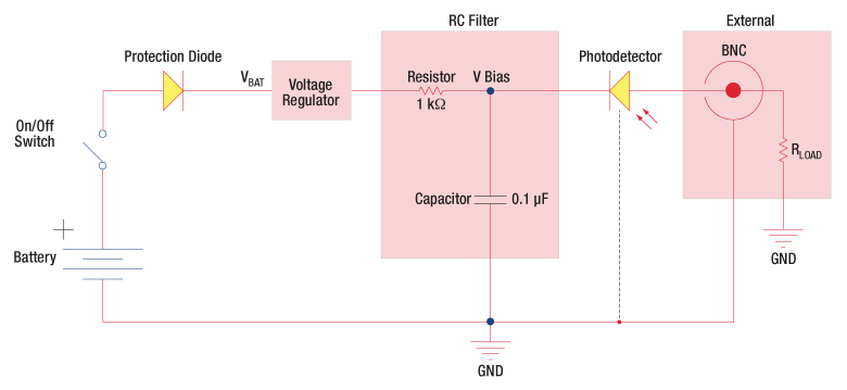
Figure 100C 逆バイアス回路(DETシリーズディテクタ)
Figure 100Cの回路はDETシリーズのディテクタをモデル化したものです。ディテクタは、入射光に対して線形の応答を得るために逆バイアス状態になっています。ここで生成された光電流の量は、入射光と波長に依存し、負荷抵抗を出力端子に接続すると、オシロスコープでモニタリングできます。RCフィルタの機能は、出力に雑音を載せてしまう可能性のある供給電力からの高周波雑音のフィルタリングです。

Figure 100D 増幅ディテクタ回路
高利得用途でアンプとともにフォトディテクタを使用できます。動作時には、PhotovoltaicモードまたはPhotoconductiveモードのいずれも選択可能です。このアクティブ回路はいくつかの利点があります。
- Photovoltaicモード:オペアンプで、点Aと点Bの電位が同じに維持されているので、フォトダイオードでは回路全体では0 Vに保たれています。このことで暗電流は発生しなくなります。
- Photoconductiveモード: フォトダイオードは逆バイアス状態であるので、接合容量を低下させ、帯域幅の状態を改善します。ディテクタの利得は、フィードバック素子(Rf)に依存します。ディテクタの帯域幅は、下記の数式で計算することができます。
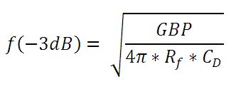
GBPが利得帯域幅積で、CDは接合容量と増幅器の静電容量の和です。
チョッパ入力周波数の影響
光導電信号は時定数の応答限界までは一定となりますが、PbS、 PbSe、HgCdTe (MCT)、InAsSbなどのディテクタにおいては、1/fゆらぎ(チョッパ入力周波数が大きいほどゆらぎは小さくなる)を持つため、低い周波数の入力の場合は影響が大きくなります。
低いチョッパ入力周波数の場合は、ディテクタの受光感度は小さくなります。周波数応答や検出性能は下記の条件の場合において最大となります。
![]()
| Posted Comments: | |
Binod Joshi
(posted 2024-09-04 15:37:40.947) Hi,
Would it be possible to obtain the raw data (or better yet, the expression for an empirical function) for the typical pulse response of DET08CFC? I have been trying to model the "Typical Pulse Response" curve on pp 12 of its User Guide, but haven't had much success. Previously, I was told by Thorlabs support that such data was not available at that moment.
Thanks. ksosnowski
(posted 2024-09-05 01:41:17.0) Hello Binod, and thank you for sharing this feedback with us. We are working to update this webpage to include a download for an excel format of this pulse response along with the plots on the Graphs tab above. I have reached out directly to discuss this further. user
(posted 2024-03-29 21:44:50.07) 最近使用附近实验室购买的这款DET08CFC/M测量脉冲光脉宽时出现了严重的拖尾,实际30ns的脉宽拖尾将近500微秒,您有对此相关的解释嘛? ksosnowski
(posted 2024-03-29 09:53:32.0) Hello, thanks for reaching out to Thorlabs. The most common issue users face with this detector is with the measurement load impedance. 50 Ohm is required as a load to get the full bandwidth of this fast detector. Some oscilloscopes with higher input impedance like 1MOhm will decrease the bandwidth unless a 50 Ohm termination resistor is used in parallel at the input. Our VT2 and FT500 around common to use for this purpose. This load directly effects the RC time constant of the photodiode system resulting in 20000x higher rise time for a 1MOhm load versus 50 Ohm. The load in Ohms also serves as the gain in V/A in this setup so 50 Ohm is expected to result in a smaller amplitude response than higher impedance measurements. If a combination of higher bandwidth and gain are needed, then a transimpedance amplifier may be necessary to readout a very small optic signal as a significant voltage. A member from your local tech support team has reached out directly to discuss this application in further detail. 子康 王
(posted 2024-03-14 12:04:48.97) 请问,这个型号的小信号的探测性能怎么样,其指标是什么 ksosnowski
(posted 2024-03-14 11:46:11.0) Hello, thanks for reaching out to Thorlabs. DET01CFC's noise floor is defined by our NEP value 4.5 x 10⁻¹⁵ W/sqrt(Hz) which is a density of RMS noise in the frequency spectrum and given at the 1:1 signal to noise ratio (SNR) point. This NEP is given near peak responsivity, so non-peak wavelengths will have proportionally higher noise floor. One must multiply the NEP value by the square root of bandwidth to obtain the optical power level of the noise floor for the system. If using the full bandwidth of DET01CFC at peak wavelength the noise floor is approximately 0.16 nW. As this is only the 1:1 SNR point, most practical setups will require a higher SNR which must be determined by the user for the application. A member from your local tech support team has reached out to discuss your application in further detail. allan bereczki
(posted 2023-08-22 07:36:19.533) Hello. does thorlabs sell replacement phtotodiode for DET08CFC? ksosnowski
(posted 2023-08-22 11:37:35.0) Hello Allan, thanks for reaching out to Thorlabs. The photodiode used in DET08x and DET02x series are not ones we sell separately. DET025x uses our FDS02 diode and DET01x uses our FGA01FC. We are however able to replace the photodiode inside these detectors if the device is damaged. I have reached out directly to discuss your application in further detail. Yazan Lampert
(posted 2023-08-11 18:31:32.743) Dear all,
we are interested in purchasing DET08CFC from you and I would like to know more about the maximum peak power you provide. Is the value 100 mW the damage threshold or is it the saturation power of the diode?
Best regards,
Yazan Lampert ksosnowski
(posted 2023-08-11 04:20:00.0) Thanks for reaching out to Thorlabs. DET08x series' 100mW max power is given by the OEM relative to the safe photocurrent limit on the microwire bonds to the sensor. Exceeding this input can generate excessive heat and damage, resulting in failure of the photodiode as an open circuit with zero current response. This is a thermal effect however the microwires will also have a very short thermal time constant so spiking past this is not recommended. This is separate from optical saturation which occurs after the output voltage passes the applied bias level. Due to the 50 Ohm load required for high bandwidth on these devices, saturation typically occurs well after the photocurrent limit. Saturation Power will depend on the load resistance and wavelength response/photocurrent which yield an output at the fixed saturation i.e. bias voltage. Saturation leads to accelerated diode aging and can cause a permanent increase in device dark current. These effects can occur relative to how far past saturation the device is operated and for how long. As saturation is where the output linearity suffers, it is not generally considered useful to operate at or past this point.
We further recommend limiting the output swing on these devices to 2V max amplitude. Typical scopes or amplifiers may see slew limited performance in a combined large signal regime with high speed operation though this does largely depend on the measurement device used on the DET. cdolbashian
(posted 2023-07-24 08:54:07.0) Thanks for reaching out to Thorlabs. The noise floor characteristics are described by the Noise Equivalent Power (NEP) spec of the detector. NEP is defined as the optical power required for 1:1 SNR in a system, considering the peak response wavelength, and normalized to 1Hz. As electrical noise occurs across a frequency spectrum, we have measured the entire bandwidth of the detector and integrated noise across this and normalized for the NEP rating. This allows you to consider various system bandwidths with a single rating. For better linearity you would want higher SNR. If you use a lowpass filter on the output of this, that could further restrict the total bandwidth, reducing the noise spectrum sampled and total noise seen. So having excessive bandwidth beyond the actual experiment will only introduce extra noise from that higher frequency part of the noise spectrum. I recommend viewing the Photodiode Tutorial tab on this page which links to our NEP whitepaper with further details on this topic. Madhav Gupta
(posted 2023-07-20 21:25:40.093) Hello
I am currently using DET025AC/M as a fluorescence detector in an optical microscope. I am using AMP100 (https://www.thorlabs.com/thorproduct.cfm?partnumber=AMP100) as a transimpedance amplifier, and trying to measure the output voltage using a standard oscilloscope or an arduino. Unfortunately, the voltage reading is quite low so I am trying to debug what the problem is.
I had a few questions:
1) Is the AMP100 compatible with DET025AC/M?
2) On the DET025AC/M webpage, the PMT transimpedance amplifier is recommended (https://www.thorlabs.com/newgrouppage9.cfm?objectgroup_id=8862). What is the main different between PMT and the AMP100? Do I need to purchase the PMT for my experiments?
Please let me know. If you think the AMP100 should work, I'll try and see if there is any alignment error in my microscope.
Also, please let me know if you suggest any other solutions on how to read out the photodiode voltage for my experiment.
Thanks a lot,
Madhav cdolbashian
(posted 2023-07-25 08:54:07.0) Thank you for reaching out to us with this inquiry. Depending on the signal you are detecting, and your instrumentation, you might be exceeding the bandwidth of the amplifier, thus seeing little-to-no amplification. The AMP100 has a maximum 1kHz bandwidth, while the PMT amplifier (TIA60) has a 3dB bandwidth of ~60MHz. I have contacted you directly to troubleshoot this issue. For future troubleshooting help, please contact techsupport@thorlabs.com as that is our dedicated support channel! user
(posted 2023-04-27 15:44:00.937) hello,
We are using DET08CFC/M photodetector to measure the rise time of a 100 ns pulse. What we expect is a perfect square pulse, but we are observing a pulse with rise/ fall time of around 50 ns (which is not expected). Can you please comment on this? (We had ensured that the battery is supplying sufficient volts)
thanks. ksosnowski
(posted 2023-05-25 11:02:14.0) Hello, thanks for reaching out to Thorlabs. The two major things that directly effect DET bandwidth are the load resistance and the diode capacitance. The battery provides the bias source which keeps capacitance low and within the designed range. Together these form an RC lowpass filter which defines the cutoff frequency for the bandwidth. I would recommend to check termination resistance, and see if reducing the input power changes the distortion. Though full saturation doesn't occur until output reaches the 10V bias level, we do recommend limiting the output on DET08 series to 2V max to prevent pulse distortion. Daniela Schubert
(posted 2023-03-16 10:14:23.76) Dear Thorlabs-Team,
which fiber-coupled photodetector do you recommend for the measurement of fs-pulses (e.g. Pav = 10mW, frep = 100MHz, Tp = 100 fs)?
Best regards ksosnowski
(posted 2023-03-17 06:35:10.0) Hello Daniela, thanks for reaching out to Thorlabs. For ultrafast pulses like this I recommend considering our FPD series detectors from Menlo Systems. FPD510-FC-VIS is one fiber coupled version with silicon photodiode. These are quite sensitive devices and would require attenuation to avoid damaging the sensor. The saturation and damage thresholds for the FPD series are given in the Specs table on our website. The DET series on this specific page are not optimized for ultrafast pulses and will see effective attenuation due to the high bandwidth of pulses in the femtosecond regime as standard photodiodes act like a lowpass filter up to their bandwidth. I have reached out directly to discuss this application further. subba rao y v
(posted 2022-10-07 13:08:32.88) Dear Sir,
We purchased the detector DET08CFC/M and also a DET2B power supply. In the description it is mentioned peak power is 100mW. Now I want to connect the CW laser. Can I connect the CW laser power of 20mW. Kindly reply the optical input power range for DET08CFC/M.
Regards,
Y. V. Subba rao. ksosnowski
(posted 2022-10-10 05:33:22.0) Thanks for reaching out to Thorlabs. We do not have an exact CW limit for the power, as this can vary with wavelength and load, but it is recommended to keep operation below saturation, and with DET08CFC we recommend further limiting the output to <2V for best bandwidth. In most cases, 20mW will saturate the sensor which can lead to early sensor degradation. There is a photocurrent limit of 0.5mA due to the DET08CFC sensor's small internal wires, this thermal effect will limit the continuous photocurrent the unit can deliver but under peak conditions it can briefly sustain higher currents. With 50 Ohm loads, this photocurrent limit will occur before saturation for the design wavelength range. Nikita Kikilich
(posted 2022-07-14 06:28:26.907) Hi. My photodetector is behaving strangely. I detect pulses with a length of 100 ns, and I see a signal in the form of a saw (very long fall time). With another photodetector from another company, everything is OK. Could you tell if the photodetector is possibly damaged? What could have led to this and what went wrong in it? Due to what did his fall time increase physically? ksosnowski
(posted 2022-07-28 04:35:07.0) Thanks for contacting Thorlabs. General technical issues like this are best direct to techsupport@thorlabs.com. Regarding these issues, I recommend to check the battery voltage is above 9V and replace if needed. Make sure to use the shortest BNC cable with no extra attachments. A higher system capacitance and load resistance will negatively effect bandwidth and rise time directly. A low battery will drop the bias voltage and raise capacitance as well. Reducing input optical power can also check if saturation is effecting the measurement speed. I have reached out directly to discuss this issue further. user
(posted 2022-05-09 16:24:20.757) Can the DET02AFC and DET025AFC be used with an FC/APC patch cable (similar to how the DET01CFC and DET08CFC can be used with FC/APC)? Thank you for the help. ksosnowski
(posted 2022-05-13 01:42:48.0) Thanks for reaching out to Thorlabs. While we have not tested the DET02AFC and DET025AFC directly with FC/APC connectors, we do not generally expect any issues with this application. It is designed to couple FC/PC cores 70um or smaller, so at this upper limit there would be some inherent loss due to the angled output, but at smaller core sizes it should have minimal effect on performance. David Conlon
(posted 2022-02-14 16:59:03.467) We have the detector DET08CFC/M and also a DET2B power supply for feeding it. Now we want to pack our system but the package of the DET2B is very big for our package. So I would ask, can we use another 12V-250mA power supply for our DET08?
What can we do for its three pin power input socket? cdolbashian
(posted 2022-02-18 04:57:52.0) Thank you for reaching out to us David. The DET2B (power supply), when used with the DET2A (power adapter) and any of the DET* detectors, will function not as a power supply, but as a reverse bias module, taking the place of the 12V battery which is already included in the DET* units. Pinout information including voltage and current requirements can be found in the spec sheet for the DET2B: https://www.thorlabs.com/_sd.cfm?fileName=TTN148688-S01.pdf&partNumber=DET2B. I have reached out to you directly to discuss your application further.
For future tech support inquiries, please feel free to reach out to us at Techsupport@thorlabs.com user
(posted 2021-08-11 10:15:42.013) I am trying to understand the difference between DET025AFC and DET02AFC. Why is the lower bandwidth option slightly cheaper? What really limits the bandwidth? The junction capacitance is the same but the bandwidths differ by 2x and the rise times by 7x (contradicting the information in the manuals). Do both feature DC-coupled outputs? cdolbashian
(posted 2021-10-15 04:39:02.0) Thank you for reaching out to us at Thorlabs! These devices have a slightly different implementation of the circuit design internally, allowing for a larger output voltage while maintaining a high bandwidth. We note in our photodiode tutorial here(https://www.thorlabs.com/newgrouppage9.cfm?objectgroup_id=10741&tabname=bias%20voltage). As the output voltage increases, the effective voltage decreases. Based on our testing, we restrict the recommended output to 2V to maintain the specced response speed. Both devices are DC coupled. I have contacted you directly to discuss this further. user
(posted 2021-08-05 11:44:25.427) Do you have a SPICE model for the detector or a diode model that closely matches the characteristics of this device? YLohia
(posted 2021-08-27 02:49:51.0) Hello, thank you for contacting Thorlabs. Unfortunately, we do not have SPICE models or any other programmatic models for our photodiodes. Daniela Manoel
(posted 2021-05-31 10:25:38.253) If I send the light into this connector using no fiber optics, directly through free space, and manage to make a measurement, can I trust the detector response? Is there any big problem in operating the DET08FCPC like this? Thanks a lot. Regards YLohia
(posted 2021-06-15 03:10:02.0) Thank you for contacting Thorlabs. These fiber-coupled detectors have a ball lens which will take the diverging light from a fiber and will refocus it on to the detector surface. Using a free space source into the fiber-coupled input will likely cause an overfilling of the detector surface, yielding an increased rise/fall time on the order of micro seconds. Properly filling (not overfilling) the detector area will yield optimal response time. user
(posted 2021-04-26 04:53:25.65) Hi, I am looking at the specs of the DET08CFC photodetector but I cannot find the sensitivity (dBm). Could you provide this value or some estimate at 1550 nm? Thank you. cdolbashian
(posted 2021-08-31 04:12:32.0) Thank you for contacting us at Thorlabs. After discussing this with you directly, I found that you were interested in the minimum detectable optical power @1550nm. This can be calculated by following the methods outlined in our NEP white paper: https://www.thorlabs.com/images/TabImages/Noise_Equivalent_Power_White_Paper.pdf Maged Esmail
(posted 2021-03-23 05:35:38.333) Hi
We have DET01CFC device in our lab. The problem is that we are not able to connect any fiber to this device. It is very strange. It looks it uses a different FC connector. Could you tell us what is this type of connectors and what is the suitable fiber connect that matches it?
Thank you asundararaj
(posted 2021-03-29 02:02:21.0) Thank you for contacting Thorlabs. The DET01CFC has an FC/PC Fiber Input Connector and an SMA connector for the Electrical Signal Output. I have contacted you for further assistance. Surjit kaman
(posted 2021-02-13 17:20:19.823) Hii,
I want it to connect the DET08CFC, to a lock-in amplifier/Oscilloscope. The scope has a 50-ohm impedance. Should I still use 50 ohm for the scope?
What is the detector output? asundararaj
(posted 2021-02-15 03:08:22.0) Thank you for contacting Thorlabs. The output of a DET08CFC is the photocurrent, and if the oscilloscope already has a 50 Ω impedance then you do not need to have an additional 50 Ω termination. In this case, the output will be read across the impedance of the scope. Nordine Hendaoui
(posted 2020-12-29 08:37:35.187) Hello,
for using the DET01CFC, We have to purchase only the DET2B as power supply. This last is powerd by 220 v?
Thanks asundararaj
(posted 2020-12-29 04:52:40.0) Thank you for contacting Thorlabs. The DET2B includes the DET power adapter and the LDS12B power supply. The power supply has a switchable AC input voltage (100, 120, or 230 VAC), which will have to be switched to 230 VAC setting. A region-specific power cord is also shipped with the LDS12B power supply based on your location. liangze pan
(posted 2020-05-18 13:10:42.937) Hey,would you mind provide the frequency response curve of the photo detector of DET025AFC/M YLohia
(posted 2020-05-27 09:39:50.0) Hello, thank you for contacting Thorlabs. Unfortunately, we do not have a frequency response curve for this detector at the moment. liangze pan
(posted 2020-05-07 15:50:29.337) Hey,would you mind to provide the frequency response curve of the photo detector of DET025AFC/M. YLohia
(posted 2020-06-09 11:16:31.0) Hello, thank you for contacting Thorlabs. I have reached out to you directly to discuss your request. Jo Wanki
(posted 2019-11-07 04:13:27.263) I have a question. I am using DET08CFC / M. I'm wondering where to fit the laser to the DET08CFC / M INPUT part when measuring the pulse width.
Currently we inspect a laser set to a 12 nsec pulse width value. If we measure from the periphery to the center of the DET08CFC / M INPUT part, a value ranging from 10.8 nsec to 13 nsec is measured.
So we wonder. Please let me know if there is any information on whether the laser should be placed in the center of the DET08CFC / M INPUT site, whether it should be around or measured. YLohia
(posted 2019-11-07 10:32:51.0) Thank you for contacting Thorlabs. For the maximum bandwidth, the spot should be <50% of the active area (ideally in the geometrical center of the photodiode). The edges of the detector tend to have a slower response time, and overfilling the detector will give a convolution of rise times across the active area. Daniel Fernando Borrero
(posted 2019-10-25 11:24:28.08) I would like to know if this detector can be used to do correlation counting experiments, I need to connect the detectors to a TCSPC module, will they work? asundararaj
(posted 2019-10-29 03:05:31.0) Thank you for contacting Thorlabs. The DET025AFC is not sensitive enough to count photons. You can find our Single Photon Counters here: https://www.thorlabs.com/newgrouppage9.cfm?objectgroup_id=5255 Philip Skochinski
(posted 2019-10-21 14:05:44.74) What is the voltage output for a given optical input? I need to be able to calculate the electrical power (in 50 Ohms) for a specific optical input power. asundararaj
(posted 2019-10-21 04:59:14.0) Thank you for contacting Thorlabs. The output voltage from the detector can be estimated from the optical power incident using following equation:
Voltage measured (V) = Optical Input (W) * Responsivity (A/W) * Terminating Resistance (Ohms)
You can find the typical responsivity in the Graphs tab of this page or in the detector Manual. user
(posted 2019-09-05 04:10:22.24) Hello,
For the DET01CFC(/M), you have specfified a Saturation Power (CW) = 5.5 mW (1550 nm) for a 50 Ohms load
But for the DET08CFC/M, it is specified a Maximum Output Voltage VOUT=2 V (Max). Could you provide me with the optical power producing this 2V or what is the Saturation Power (CW) in mW for this detector? I aks this because I have a fast modulation (GHz) on top of CW light level.
Thanks! asundararaj
(posted 2019-09-06 04:19:13.0) Thank you for contacting Thorlabs. The saturation threshold of a detector depends on many factors such as load resistance value, beam profile and size, modulation characteristics, wavelength, bias voltage, diode temperature, etc. For more details regarding this, please see our "Lab Fact" on photodiode saturation limits here: https://www.thorlabs.com/images/TabImages/Photodetector_Lab.pdf.
We do not have an official spec on the saturation of the DET08CFC. I will reach out to you directly to discuss this further. jwchew33
(posted 2018-07-09 01:53:12.373) Greeting, I have a problem on DET08CFC/M. When I input square waveform at frequencies range from 1kHz to 1MHz into the photodetector, the output results did not show square waveform as expected. However, by using the same setup using PDA50B-EC detector (input 1kHz-400kHz), square waveform were observed. The pulse width used was 10us. I'm not sure what to do next. Any help? Thanks. YLohia
(posted 2018-07-25 08:43:15.0) Hello, thank you for contacting Thorlabs. What load impedance are you using on your oscilloscope? You should be using 50 Ohms for ideal performance. Is the battery for the DET fully charged? I will reach out to you directly to troubleshoot this further. dlee103
(posted 2018-03-16 15:55:18.063) What is the saturation threshold in mW? YLohia
(posted 2018-04-19 03:39:43.0) Hello, thank you for contacting Thorlabs. The saturation threshold of a detector depends on many factors such as load resistance value, beam profile and size, modulation characteristics, wavelength, bias voltage, diode temperature, etc. For more details regarding this, please see our "Lab Fact" on photodiode saturation limits here: https://www.thorlabs.com/images/TabImages/Photodetector_Lab.pdf. The DET025AFC is designed for pulsed/modulated light sources so the saturation limit can depend heavily on modulation characteristics. For example, a few milliwatts (1 to 2 mW for peak wavelength) is a safe theoretical estimate for CW sources, while we spec 18mW of peak power for pulsed sources. There is a resistor in series as a part of an RC circuit within the detector packaging, which limits the CW saturation power. user
(posted 2016-11-04 16:39:22.64) The manual linked for DET01CFC says that the battery should be installed negative side in. The diagram on the detector and the spring inside the battery cap suggest the opposite is true. tfrisch
(posted 2016-11-04 04:50:19.0) Hello, thank you for contacting Thorlabs. Section 4.11 of the manual calls for the battery to be inserted into the cap with the negative terminal inside the cap (in contact with the coil spring). When the cap is threaded back onto the housing, that will put the positive of the battery in the housing. mitch
(posted 2016-03-22 09:10:48.767) Hi, would it be possible for me to buy the metal fibre attachment that is attached to the input of these devices, by itself? I have purchased four of the free space, window versions (along with several tens of thousand dollars of other stuff) but I would like to try attach a fibre and I don't want to buy another set (the budget is now mostly spent!). Thanks besembeson
(posted 2016-03-24 10:23:31.0) Response from Bweh at Thorlabs USA: The sensor for the fiber versions comes coupled to the fiber connector. I will contact you if this is still suitable for your application. songtaodu
(posted 2016-01-21 17:08:49.07) When I used DET08CFC to detect output light of a fiber laser,wavelength of this laser is 1550nm and output is CW, the output voltage of DET08CFC kept at 13.2V while the laser power varied from 0.5mW to 3mW.
When I turn off the laser, the output voltage of DET08CFC is zero.
Can you tell me why this happened? Thanks! jlow
(posted 2016-01-22 01:28:18.0) Response from Jeremy at Thorlabs: It seems like you are basically measuring the voltage of the battery. The DET08CFC output s current signal. To use that with an oscilloscope or a voltmeter, you will need a load resistor or a terminator in series and measure the voltage drop across the resistor /terminator instead. An example of the terminator would be the T4119 terminator. rmillett
(posted 2014-09-03 11:28:46.62) Could a calibrated transfer curve be available for these detectors? In particular a response curve that could be calibrated out from low (kHz) frequencies to 5GHz? jlow
(posted 2014-09-04 04:06:29.0) Response from Jeremy at Thorlabs: We will look into measuring this and will e-mail you directly on our findings. kmurari
(posted 2013-05-03 16:17:01.92) My DET02AFC appears to be AC coupled although the manual says the SMA output is DC coupled. I have checked the battery, it is at >12 V. Can you please confirm if the unit is indeed DC coupled?
Thanks! jlow
(posted 2013-05-03 18:07:00.0) Response from Jeremy at Thorlabs: The DET02AFC should be DC-coupled. I will contact you directly to troubleshoot this. jlow
(posted 2012-12-21 10:39:00.0) Response from Jeremy at Thorlabs: The detector's active area has a diameter of Ø120µm. There's also a Ø1.5mm ball lens in front of the detector. The output from a SMF28 fiber should be fully captured by the detector. For MM fiber, we recommend using a fiber with at most 50µm core size (around 0.2 NA). neil.troy
(posted 2012-12-06 00:01:17.15) For the fiber coupled devices will a single mode fiber's (say SMF-28 for example) divergence be fully captured by the detector? What about a multi-mode fiber? ie. what is the distance from the output face of the fiber to the detector surface as well as what are the detector's active areas? tcohen
(posted 2012-04-05 15:19:00.0) Response from Tim at Thorlabs to jzheng: Thank you for your feedback! The typical rise time of the DET02 will still be ~50ps at your wavelength. jzheng
(posted 2012-03-26 01:56:40.0) For the wavelength 1053nm, is the rise time of the DET02 (Si) still be 50ps? or will be longer? thank you. jjurado
(posted 2011-02-08 18:27:00.0) Response from Javier at Thorlabs to last poster: Thank you very much for submitting your request. For the high bandwidth detectors, a switch is not included since it significantly impairs the BW performance of the detector. In general, the DET’s draw very little current when no light is applied to the sensor. A battery will last on the order of years without a light signal applied. For these detectors, it is recommended that the light source is removed from the sensor when not being used. This will preserve the battery life. user
(posted 2011-02-08 17:00:05.0) It looks free space DET series has a battery switch. Do I have to remove a battery out of a box of the fiber input DETs every time? klee
(posted 2009-10-05 14:39:34.0) A response from Ken at Thorlabs to dinglu81: Thank you for pointing out the discrepancy. It should be 10^-15. dinglu81
(posted 2009-10-02 05:41:25.0) the NEP of this detector is 10^-15 in the specs but 10^-14 in the catalog. Which one is correct? Greg
(posted 2009-02-18 15:37:16.0) A response from Greg at Thorlabs to remi.riviere: Thank you for your interest in Thorlabs products. Please see the e-mail I sent you and reply to it with the detector you are looking for more information on. I will then check what other information we have available on it. remi.riviere
(posted 2009-02-18 05:01:42.0) Please provide a gain curve as well as the dynamic range of this detector. acable
(posted 2008-08-31 12:59:35.0) Please add NEP data. |
下表は、当社のフォトダイオードタイプのディテクタ、フォトコンダクティブ型ディテクタ、焦電ディテクタの一覧です。同一の列に記載されている型番の検出素子は同じです。

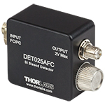
Click to Enlarge
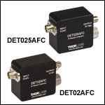
ディテクタDET025AFC(/M)のSMA出力端子
- DET02AFC/M: 1 GHz帯域幅、立ち上がり時間1 ns
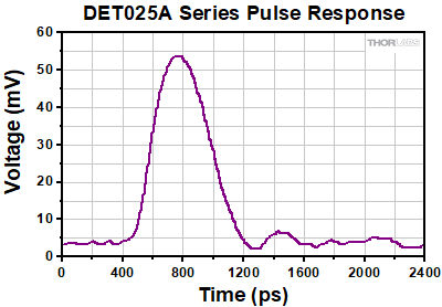
- DET025AFC/M: 2 GHz帯域幅、立ち上がり時間150 ps
高速、ファイバ入力ディテクタDET02AFC/MおよびDET025AFC/Mは、400~1100 nmのスペクトル範囲で使用できる設計です。Si検出素子を使用したフォトダイオードFDS02がベースとなっており、帯域幅はそれぞれ1 GHzおよび2 GHzです。M4の取付け用のネジ穴を使うことで、Ø12 mm~Ø12.7 mm(Ø1/2インチ)ポストに簡単に取り付けられます。
| Item # | Wavelength | Detector | Bandwidth | Max Peak Power | Rise Time | Fall Time |
|---|---|---|---|---|---|---|
| DET02AFC | 400 - 1100 nm | Si | 1 GHz | 18 mW | 1 ns (Max) | 1 ns (Max) |
| DET025AFC | 400 - 1100 nm | Si | 2 GHz | 18 mW | 150 ps (Typ.) | 150 ps (Typ.) |

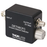
Click to Enlarge
ディテクタDET08CFC(/M)のSMA出力端子
- DET01CFC/M: 1.2 GHz帯域幅、立ち上がり時間<1 ns
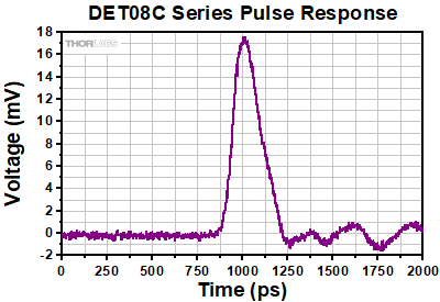
- DET08CFC/M: 5 GHz (Max) 帯域幅、立ち上がり時間 70 ps
DET01CFC/Mは、800~1700 nmのスペクトル範囲で使用できる設計です。 InGaAs検出素子が組み込まれたフォトダイオードFGA01FCがベースとなっており、帯域幅は1.2 GHzです。FC/PC入力コネクタが付いていますが、当社の試験によると性能に目立った差が生じないため、FC/APCパッチケーブルもお使いいただけます。M4の取り付け用タップ穴により、Ø12 mm~Ø12.7 mm(Ø1/2インチ)ポストに取り付けられます。
DET08CFC/Mは、800~1700 nmのスペクトル範囲で使用できる設計です。 InGaAs検出素子を使用しており、帯域幅は5 GHz (Max)です。FC/PC入力コネクタが付いています。M4の取付け用タップ穴により、Ø12 mm~Ø12.7 mm(Ø1/2インチ)ポストに取り付けられます。
| Item # | Wavelength | Detector | Bandwidth | Max Peak Power | Rise Time | Fall Time |
|---|---|---|---|---|---|---|
| DET01CFC | 800 - 1700 nm | InGaAs | 1.2 GHz | 18 mW | < 1 nsa | < 1 nsa |
| DET08CFC | 800 - 1700 nm | InGaAs | 5 GHz (Max) | 100 mW | 70 ps (Typ.) | 110 ps (Typ.) |

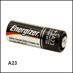
A23は当社が現在販売しているDETフォトディテクタの交換用アルカリ電池です。バッテリ寿命が問題となる用途向けには、ACアダプタもご用意しています。詳細は下記をご参照ください。バッテリの期待寿命につきましては、上の「電池寿命」タブをご参照ください。

- DET2A:DETシリーズディテクタ用の電源アダプタ
- LDS12B:±12 VDCの電源
- DET2B::DET2AとLDS12Bのセット
電源アダプタDET2A
DET2Aは、当社のDETシリーズディテクタ用の電源アダプタです。バッテリA23とバネ式のバッテリーキャップに代えて、電源LDS12B(別売り)をディテクタに接続して直接駆動することができます。また、カスタム接続用に電源ケーブルPDA-C-72と使用することもできます。DET2AとPDA-C-72を接続してDETシリーズディテクタに電源を供給する場合は、茶色(+12 V)および黒色(GND)のピンのみ使用します。
電源LDS12B
LDS12Bは±12 VDCの安定化電源で、短絡やオーバーロードに対する保護用の電流リミット機能、LED表示付きのOn/Offスイッチ、AC入力電圧の切り替えスイッチ(100/120/230 VAC)が付いています。尚、電源LDS12Bには日本国内向けの電源ケーブルが付いています。
電源アダプターセットDET2B
電源アダプターセットDET2Bには電源アダプタDET2Aと電源LDS12Bが含まれています。こちらの電源アダプターセットは当社のDETシリーズのディテクタのバッテリの代わりにご使用可能です。ディテクタのバッテリとバネ式のバッテリーキャップを付属のアダプタDET2Aと交換し、電源LDS12Bの3ピンのプラグをアダプタに接続するだけでお使いいただけます。使用方法は、右の動画でご覧になれます。
 Products Home


 ズーム
ズーム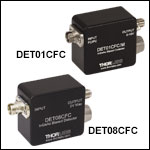
 光ファイバ用高速バイアスディテクタ