 Products Home
走査型ファブリペロー干渉計

- Operating Wavelength Ranges from UV to MIR
- Custom Mirror Coatings from UV to Mid-IR Available
- Controller for Scanning Fabry-Perot Interferometers
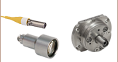
SA201B
Voltage Controller
(Sold Separately)
SA210-8B
10 GHz FSR, 820 - 1275 nm
SA200-2B
1.5 GHz FSR, 290 - 355 nm & 520 - 545 nm
Application Idea
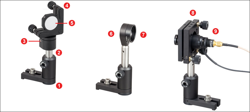
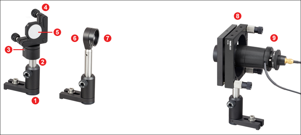
Mounting components on an optical rail system reduces the degrees of freedom while aligning the beam to the cavity. The SA200, focusing lens, and laser are each mounted to an XT66C4 clamping platform which centers the optical axis over the XT66-500 rail axis.


Please Wait
共焦点ファブリペロー干渉計の概略図
各ファブリペロー干渉計は熱安定性に優れたインバー(Invar®)製共振器が採用されています。
特長
- CWレーザの微細なスペクトル特性の解析
- 波長範囲290 nm~4400 nmに対して8種類のコーティング(詳細は「グラフ」タブ参照)
- フリースペクトルレンジ:1.5 GHzまたは10 GHz
- フィネス(最小値):150、200、または1500
- フィネスは工場で校正済み
- 熱的安定性に優れたインバー(Invar®)製共振器
- SMAまたはBNCコネクタでオシロスコープに接続
- コントローラSA201B(別売り)は、ピエゾトランスデューサを三角波または鋸歯状波で走査する電圧信号を供給
- UV~中赤外域でカスタム仕様のミラーコーティングを承ります(詳細は当社までお問合せください)。
走査型ファブリペロー(FP)干渉計は、CWレーザの微細なスペクトル特性を調べるのに適したスペクトラムアナライザです。当社では、フリースペクトルレンジ(FSR)が1.5 GHzまたは10 GHzの干渉計をご用意しております。分解能はFSRとフィネスによって1 MHz未満~67 MHzの範囲で変化します。これらの物理量に関する詳細やそのファブリペロー干渉計での扱い方については、「ファブリペローチュートリアル」のタブをご覧ください。
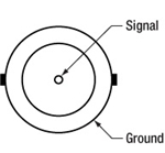
共焦点ファブリペロー共振器は、特定の周波数の光のみを透過します。この透過周波数は、ピエゾトランスデューサで共振器長を調整することでチューニングできます(右図参照)。透過光強度はフォトダイオードで測定され、コントローラSA201B内のトランスインピーダンスアンプ(または同等のアンプ)で増幅されたのち、オシロスコープまたはデータ収集カードによって表示または記録されます。各ファブリペロー干渉計には、BNCコネクタで終端されたピエゾ制御用ケーブルが付属しています。
SA30-144、SA200-18CおよびSA210-18CのミラーはIRグレードの溶融石英(Infrasil®)製、SA200-30CのミラーはYAG製、その他のモデルのミラーはすべてUV溶融石英製です。 ファブリペロー干渉計は熱的安定性に優れたインバー製で、温度変動に伴うミスアライメントを抑制します。

SA200ならびにSA30シリーズにはSM1ネジ、SA210シリーズにはSM05ネジがそれぞれの背面に付いており、共にディテクタを取り付けることができます。
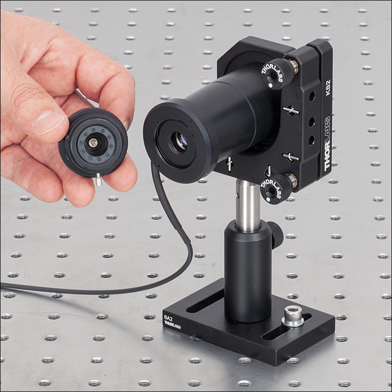
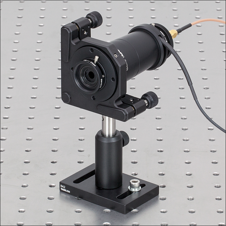
ディテクタと後部アイリスの取外し方法
SA200とSA30シリーズにはSM1ネジ、SA210シリーズにはSM05ネジがそれぞれの背面に付いており、共に可変アイリスとディテクタを取り付けることができます。各走査型ファブリーペロー干渉計には、デバイスの入射口と出射口の両方にレバー作動式のアイリスが付いています。またSA200-30Cを除くすべてのファブリーペロー干渉計にフォトダイオードディテクタが付属し、そのほかにディテクタと増幅器を接続するためのSMA-BNCケーブルも付属します。アライメントを容易にするため、フォトダイオードディテクタは、ネジを緩めて後部のアイリスから取り外すことができます。詳細は「アライメントガイド」タブかデバイスのマニュアルをご覧ください。アイリスも同様に取外すことは可能ですが、アライメント中はアイリスを取り付けたままにしておくことを推奨します。必要であれば、ディテクタを外してほかのディテクタと交換することができます。
アライメント
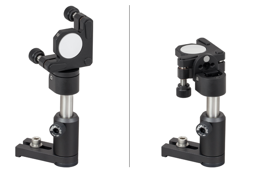
ファブリペロー干渉計共振器のコンフォーカル(SA200/SA210シリーズ)またはニアコンフォーカル(SA30シリーズ)の設計により入射ビームのアライメントは容易です。ファブリペロー干渉計を標準タイプのキネマティックミラーマウントに取り付け、「アライメントガイド」タブの手順に従うことで、ファブリペロー干渉計の光軸を入射ビームに対して十分な精度でアライメントできます。右の写真はSA200シリーズのファブリペロー干渉計を当社のキネマティックマウントKS2に取り付けた例です。
ニアコンフォーカル設計のSA30シリーズでは、干渉計を適切にアライメントするために追加の手順が必要です。このシステムでは、透過モードの観察中に高次モードを抑制するため、さらに微調整が必要となります。詳細は「アライメントガイド」タブをご覧ください。
コントローラ
SA201B(別売り)は鋸歯状波や三角波の電圧信号を生成し、干渉計のFSRの範囲を掃引するために繰返し共振器長を変化させます。コントローラSA201Bには、ファブリペロー干渉計のフォトダイオードディテクタからの出力を増幅するトランスインピーダンスアンプも内蔵されています。このディテクタでは共焦点ファブリペロー共振器の透過光強度を測定します。またこのコントローラはオシロスコープに対してトリガ信号を出力することも可能です。このトリガ信号は走査の開始時だけでなく、走査範囲内でその位置(タイミング)を設定することも可能です。オシロスコープの時間軸は、FSRだけ離れた隣り合うピーク間隔を測定することにより、精密に周波数軸として校正できます(詳細は「校正」タブをご覧ください)。ファブリペロー干渉計、コントローラ、およびオシロスコープの接続に関する詳細は「接続」タブをご参照ください。
下のグラフの青線は、当社のファブリペロー干渉計のミラーの反射率を示しています。ミラーフィネス(Mirror Finesse)は、ミラーの反射率によって決まるフィネスを示しています。ほぼ完全にアライメントされたシステムでは、ファブリペロー共振器のフィネスはミラーの反射率によって制限され、フィネスの値は下のグラフに近づきます。フィネスについての詳細は「ファブリペローチュートリアル」タブをご参照ください。
ミラーの実際の反射率はコーティングロットにより規定スペクトル領域内では僅かに異なり、領域外では大幅に異なることがあります。キャビティのフィネスは他の要素によって変わります。詳細は「ファブリペローチュートリアル」タブをご参照ください。
UV~中赤外域(200 nm~4700 nm)におけるカスタム仕様のミラーコーティングも、ご要望に応じて承ります。グラフに示したコーティングでご用途に適した製品が無い場合は、当社までお問い合わせください。
干渉計(フィネス ≥1500)


干渉計(フィネス> 150または> 200)
反射率とミラーフィネスの理論値。ミラーフィネスは「ファブリペローチュートリアル」タブの(8)の式を用いて計算されています。なお、機器の実際のフィネスには、基板の表面品質のフィネスも考慮する必要があるため、こちらの曲線の値よりも低くなります(「ファブリペローチュートリアル」タブの(10)の式参照)。


Click to Enlarge
反射率データの測定値とミラーフィネスの計算値はこちらからダウンロードいただけます。 このデータでは、空気中の水蒸気による吸収によって測定に不確かさが生じるため、2.65~2.7 µmの波長範囲で平滑化されています。
| Recommended Beam Sizes and Lenses for FP Interferometers | ||
|---|---|---|
| Item # Prefix | EFLa | Waist Radiusb |
| SA200 | 250 mm | 600 µm (Max) |
| SA210 | 100 mm | 150 µm (Max) |
| SA30 | See SA30 Series Recommendation | |
下記では当社のファブリペロー干渉計のアライメント方法の概要を説明しています。下のリンクから特定の説明に飛ぶことができます。
Click to Enlarge
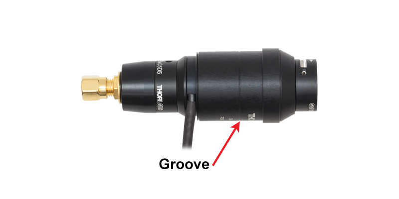
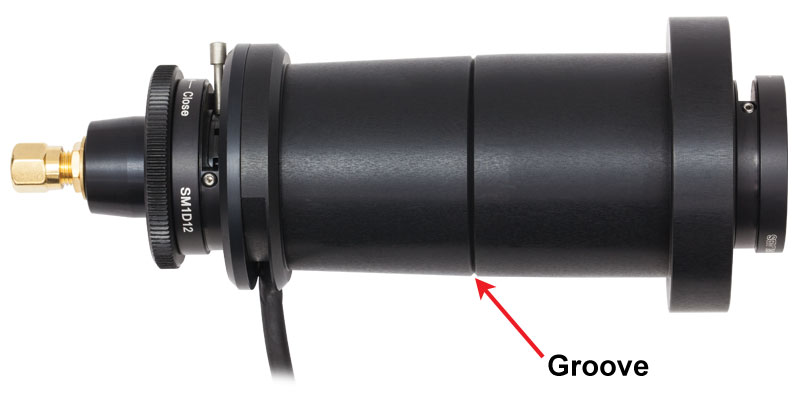
図2:SA210シリーズ干渉計の中心は機器本体の溝で示されています。
Click to Enlarge
図1:SA200シリーズ干渉計の中心は機器本体の溝で示されています。 SA30シリーズの本体と溝はSA200シリーズと同じです。
一般的な手順
当社の走査型ファブリペロー干渉計は、機器を標準のキネマティックミラーマウント(SA200とSA30シリーズにはKS2、SA210シリーズにはKS1)に取り付け、それを折り返しミラーの後の自由空間ビーム中に配置することでアライメントすることができます。共振器を走査しながら、共振器が入射ビームに対してアライメントされるまでミラーとFP干渉計の位置を繰り返し調整してください。共振器をビームに対してアライメントした後、ビームウエスト(半径)が共振器の中心において規定値となるようにレンズ位置を調整してください。共振器の外側の筐体には、共振器の中心の位置を示す溝が付いています(図1および2参照)。
SA30シリーズの推奨するビームウェストとレンズ
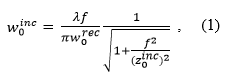
SA30シリーズでは、レンズの有効焦点距離と位置はレンズに入射するビームのパラメータに依存しており、推奨するウェスト半径を得るためには適切なレンズを選択する必要があります。レンズに入射するビームの推奨ウェスト半径は下記の式で求められます。
Click to Enlarge
図3:集光レンズに入射されるビームのウェスト半径(w0inc)と、干渉計中心位置における推奨ビームウェスト半径(w0rec)の図解。
このときw0incはレンズの入射されるビームウェスト半径、w0recは干渉計の中心における推奨ビームウェスト半径、z0incはレンズに入射するビームのレイリ長、λは入射ビームの波長、 fはレンズの焦点距離です。よくコリメートされたビーム、つまり入射ビームのレイリ長がレンズの焦点距離より大幅に大きく、ビームがほとんど広がっていかない場合、式(1)は下記のように近似されます。
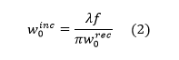
レンズは距離D分
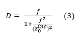
中心の溝から離してください。これによりよくコリメートされたビームの場合、D = fに近似されます。なお、ガウシアンビームのレイリ長はz0 = πw02/λ(w0がビームウェスト半径、λが入射光の波長)によって求められます。
SA30シリーズに推奨するウェスト半径は下記の式で求められます。
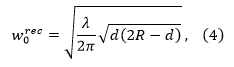
このときRはミラーの曲面半径(50 mm)、dは2つのレゾネーターミラー間の距離(50 mm)、λは入射ビームの波長です2。
自由空間ビームの走査型ファブリペロー干渉計へのカップリング
Click to Enlarge
図4:SA210シリーズFP干渉計と自由空間ビームのカップリング用システム
Click to Enlarge
図5:SA200シリーズFP干渉計と自由空間ビームのカップリング用システム
| Fabry-Perot Alignment Setup Parts List | |||||||
|---|---|---|---|---|---|---|---|
| Callout # | Item # | Qty. | Description | Callout # | Item # | Qty. | Description |
 | UPH2 | 3 | Universal Post Holder, L = 2.00" |  | LMR1 | 1 | Lens Mount for Ø1" Optics |
 | TR3 | 3 | Ø1/2" × 3" Stainless Steel Optical Post |  | LA1461-A-MLb LA1509-A-MLb | 1 | f = 250 mm Mounted, Visible Plano-Convex Lens (SA200) f = 100 mm Mounted, Visible Plano-Convex Lens (SA210) |
 | FM90 | 1 | Flip Mount |  | KC2L KC1L | 1 | Kinematic Cage Mount for 2" Components (SA200) Kinematic Cage Mount for 1" Components (SA210) |
 | KM100 | 1 | Kinematic Mount for Ø1" Optics |  | SA200 SA30 SA210 | 1 | Fabry-Perot Interferometer |
 | BB1-E02a | 1 | Ø1" Broadband Dielectric Mirror | ||||
Click to Enlarge
図6:フリップミラーを起こすと(左)、ビームをインターセプトして光を干渉計の方向に向けます。 フリップミラーを倒すと(右)、ビームを下流の光学系の方向に向けることができます。
図4はSA210シリーズFP干渉計を自由空間ビームの光学系に組み込むためのセットアップです。図5はSA200シリーズを使用する場合の同様なセットアップです。フリップマウントと干渉計用キネマティックマウントを使用して、簡単に組み込むことができます。フリップミラーの利点は、光学素子や装置を移動させることなく、必要に応じて、光源のスペクトルを測定できる機能を持たせたまま、通常の光学動作が可能になることです。通常動作の間は、ビームの光路を妨げないようミラーを倒し、ビームの伝播を邪魔しないようにできます。必要な時には、ミラーを起こしてビームを遮断し、干渉計のほうに導くことができます(図6)。図4のシステムではミラーを1枚使用しています。そのフリップミラーでビームをインターセプトし、ビームを集光レンズとキネマティックマウントに取り付けられた干渉計の方向に向けています。スペースと必要部品が最小限に抑えられており、セットアップがコンパクトで便利です。
SA210シリーズFP干渉計はキネマティックマウントKC1L/Mに取り付けられます(KS1も同様にお使いいただけます)。一方、SA200シリーズFP干渉計はキネマティックマウントKC2L/Mに取り付けられます(KS2も同様にお使いいただけます)。図4と図5ではマウント付きレンズをレンズマウントLMR1(/M)に取り付けていますが、マウント無しレンズもマウントに取り付けられます。使用する光学素子(ミラーおよびレンズ)はシステムの波長によって決まります。
アライメント手順
テーブル表面からのビームの高さを測定します。一般に、光学素子の中心をビームの高さに合わせることから始めるのが適切です。ミラーを取り付けたフリップミラー(ミラー付きのミラーマウント、フリップマウント、ポスト、ポストホルダ)を立てた状態にし、ビームに対して45°の角度に設置します。ちょうど90°ビームを曲げることで、最初のアライメントや、より精密にアライメントするためのビームの調整が簡単にできます。作業をはじめる時、光学テーブルのタップ穴の間隔と直角はよい目安となります。
ビームを90°の角度で反射するようにフリップミラーアセンブリを配置し、M6ネジでテーブルに固定します。まず、ビームが開口の中心に入るように干渉計を取り付けて下さい。アライメントのガイドとしてアイリスをお使いいただくことも可能です。干渉計の中心線の高さがビームの高さにうまく合っている場合、最初の配置でも概ね上手く機能するので、次に示す共振器長走査により信号が見えるはずです。その後、フリップミラーのキネマティックマウントと、干渉計のキネマティックマウントを調整してビームを適切なアライメントに誘導します。
ファブリペロー干渉計の制御ボックス(コントローラ)の電源を入れて共振器長の走査を開始します(ピークが1つ以上表示されるように振幅は10 V以上に設定)。走査する理由は、共振器長が入射ビームの波長に共鳴した時にしか光が透過しないためです。ディテクタの出力とトリガ(またはランピング信号)をオシロスコープに接続します。この時点で信号が検出されない場合、共振器を大まかに位置合わせするためにファブリペロー共振器の後ろからディテクタを取り除かなければならない可能性があります。干渉計の後ろに配置されたアイリスをアライメントのガイドとしてお使いいただくこともできます。しかし、光学素子を最初に配置する際に十分な注意を払っていただけるのであれば、このようなことは必要ないはずです。干渉計を保持しているキネマティックマウントとフリップミラーを用いて、FP共振器が正しくアライメントされるまでビームの高さと方向を調整します。
ビームウエストがFP共振器の中央(FPの筐体に溝で示されています。図1および2参照)に来るように、光路中の適切な位置にレンズ(上表に従ってください)を設置します。レンズの高さと位置は、入射開口の中心にビームが入射するように調整してください。ミラーと干渉計のマウントを調整して、信号が適切なレベルに戻るよう調整します。
SA30シリーズ特有の追加のアライメント手順
SA200およびSA210の両シリーズに比べて、SA30シリーズではシステムを適切にアライメントするためにいくつかの追加作業が必要になります。上記のアライメント作業の後、透過光の1つのモードを拡大表示し、高次モードが最も抑制されるように、さらにアライメントの微調整を行ってください。こうした高次モードは、通常、基本の透過モードの数MHzの範囲内で発生します。この調整を行うときは、スペクトルの中から大きい透過モードの1つを選んでオシロスコープに設定すると便利です。適切なアライメントを実現して高次モードを抑制するには、レンズ位置の微調整も必要になる場合があります。下の図は、高次モード抑制のためのアライメント調整を行う前と後の透過スペクトルの例を示しています。
SA201Bシリーズの制御ボックスの出力スペクトルが内蔵フィルタの影響を受けないようご注意ください。すべての利得設定において時間ベースのFWHMモード幅の最小値は4 µsです。この値に近づいてきた場合、SA201Bでより低い増幅レベルに変更するか、PZT設定(振幅、立ち上がり時間、または掃引拡張)を変更し、掃引速度を下げます。
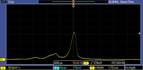
この図ではまだ高次の横モードが現れています。このセットアップでは適切なアライメントを実現するために更なる調整が必要です。
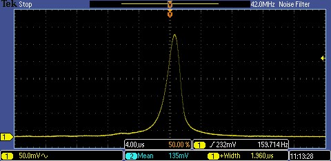
この図では高次モードは抑制されています。このセットアップは適切にアライメントされています。
参考文献
- P. W. Milonni and J. H. Eberly, Lasers (John Wiley & Sons, Inc., 2010) p. 290.
- H. Kogelnik and T. Li, "Laser Beams and Resonators," Applied Optics, vol. 5, no. 10, 1966.
接続
ここでは、ファブリペロー干渉計、制御ボックスSA201B、およびオシロスコープの接続について説明します。コントローラSA201Bは、ファブリペロー共振器の共振器長を制御するピエゾトランデューサにランプ電圧信号を送信します。オシロスコープは、走査型ファブリペロー干渉計およびコントローラからの出力信号を観測するために使用します。

Click to Enlarge
SA30、SA200、およびSA210シリーズのファブリペロー干渉計用として推奨するセットアップ(右図のSA200-30Cを除く)

Click to Enlarge
ファブリペロー干渉計SA200-30C用として推奨するセットアップ
| Connection | Description |
|---|---|
| 1 | Controller (BNC) to Piezo (Cable is Attached to FP Interferometer) |
| 2a | Photodiode (SMA) to Controller (BNC) (Included with FP Interferometer) |
| 3a | Amplified Photodiode Output (BNC) to Oscilloscope (Not Included) |
| 4 | Trigger Output of Controller (BNC) to Oscilloscope (Not Included) |
| 5 | Optional Connection that Allows the User to Monitor the Signal used to Drive the Piezoelectric Transducers (Not Included) |
| 6b | PDAVJ5 Output (BNC) to Oscilloscope (Detector and Cable Not Included) |
SA30、SA200、およびSA210シリーズ走査型ファブリペロー干渉計
ピエゾ入力端子(ランプ信号入力) -BNCオス型
最大150 V
フォトダイオード出力端子 - SMAメス型
SMA-BNCケーブルが付属しています(ディテクタが付属しないSA200-30Cを除く)。
走査型ファブリペロー干渉計用制御ボックスSA201
PD増幅器出力端子 - BNC
このBNC端子は増幅器の出力端子で、オシロスコープに直接接続して共振器のスペクトルをモニタできます。増幅器の利得は制御ボックスの前面パネルにあるLCDメニューで設定できます。増幅器の出力回路には、50 Ωの同軸ケーブルを接続して使用したときにノイズを最小化できるように、200 Ωの抵抗が直列に接続されています。
トリガ出力端子 - BNCメス型

出力端子 - BNCメス型
このBNC出力端子はファブリペロー干渉計の駆動用で、出力電圧は1~45 Vです。当社のファブリペロー干渉計のピエゾ素子を、出力電圧の全範囲にわたり1 msのランプレートで駆動できます。出力駆動回路を損傷しないように、出力電流は内部で制限されています。
PD増幅器入力端子 - BNC
このBNC入力端子は、走査型ファブリペロー干渉計(SA200-30C以外)に取付けられているフォトディテクタと、SA201内の増幅回路とを接続するインターフェイスです。このフォトダイオード用の増幅器は、当社が提供するフォトディテクタ用として設計されていますが、お客様がお持ちのフォトディテクタでもご利用いただけます。ただしその場合は、BNCのセンターコンタクトピンはフォトディテクタのカソードに、 BNCシェルはフォトダイオードのアノードに接続しなければなりません(バイアス無しで使用する場合)。バイアスディテクタを使用する場合、回路を正常に動作させるには、BNCシェルをバイアス電圧のアース側に接続し、バイアス電圧を負電圧にしなければなりません。
モニタ出力端子 - BNC
モニタ出力用のBNC端子からは、出力ランプ信号を減衰させて出力します。内部回路で駆動用の出力信号を1/10に減衰させるため、45 Vの駆動信号はモニタ信号では4.5 Vになります。この信号は高インピーダンス負荷を駆動できるため、オシロスコープへの入力に適しています。
オシロスコープの時間スケールの校正
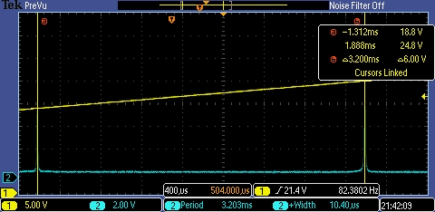 図1:FSRのグラフ、1550 nm DFBレーザ(PRO8000シリーズ)を使用。SA200-12Bの1.5 GHz干渉計を使うことで、このグラフはオシロスコープの時間基準の校正に利用できます。干渉計のFSRが1.5GHzであることが既知であれば、2つのピーク間を1.5 GHz = 3.2 msと設定して校正係数を求めることができます。
ファブリペロー干渉計を透過した光は、「接続」タブの手順を踏むことでオシロスコープ画面に表示させることができます。測定結果が光周波数で決定されるため、レーザまたは共振器のモード幅の定量的測定を行う前に、オシロスコープの時間スケールを校正する必要があります。
図1と図2では1.5 GHz干渉計SA200-12Bを使用して時間スケールを手動で校正するプロセスが示されています。図1では干渉計のフリースペクトルレンジ(FSR)全体を、1.5 GHzで離れている2つのピークとともに示しています。また、黄色の直線はランプ電圧を示しています。ピーク間の時間を測定することで(ここでは3.2 ms)、正確な校正値が算出できます。この例では、468.8 MHz/msとなります。時間スケールの校正値が分かったら、片方のピークを拡大してFWHMを測定することができます(図2参照)。この例で測定されたFWHMは10 µs(0.010 ms)で、線幅は4.7 MHzとなります。
より高度なオシロスコープの一部では、線幅と周期分析は自動で行われます。このようなオシロスコープでは一般的に、図3のように情報はスクリーン上に表示されます(この場合は、1番下に表示されています)。
FSRもしくは線幅を波長の単位で表すと良い場合があります。下記の式により変換します。

このときδλは空間上のFSRまたは線幅、δνは周波数内のFSRまたは線幅、λはレーザ波長、cは光の速度です。例えば、図2での1550 nmレーザの1.5 GHzのFSRが分かります。このFSRを波長へ変換すると0.0121 nmとなります。同様に、図3の線幅5.1 MHzからは線幅0.000038 nmが得られます。
なお、当社では工場でフィネスの校正を行っており、校正証明書が各ユニットに添付されています。
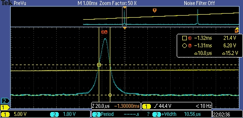
図2:このグラフはレーザの実際の信号状態を拡大したもので、レーザ線幅と共振器のフィネスの畳み込みの結果です。ここではオシロスコープの時間基準が図1の状態から校正されて468.8 MHz/msになっています。したがって、この干渉計のFWHMは、0.010 ms x 468.8 MHz/ms=4.7 MHzとなります。
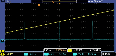
図3:こちらは、パルス幅と間隔を自動解析したスコープ上のFSRのグラフです。黄色の線はランプ電圧を示し、青い線はFSRを示しています。
走査型ファブリぺロー干渉計
ファブリぺロー干渉計は、高分解能分光用の光共振器です。透過スペクトルの微細な特徴を高精度で検出および分解できるため、狭い線幅で狭い間隔のスペクトルピークを有するレーザ共振器の共振モードを決定するために使用されます。
空間モード構造
Click to Enlarge
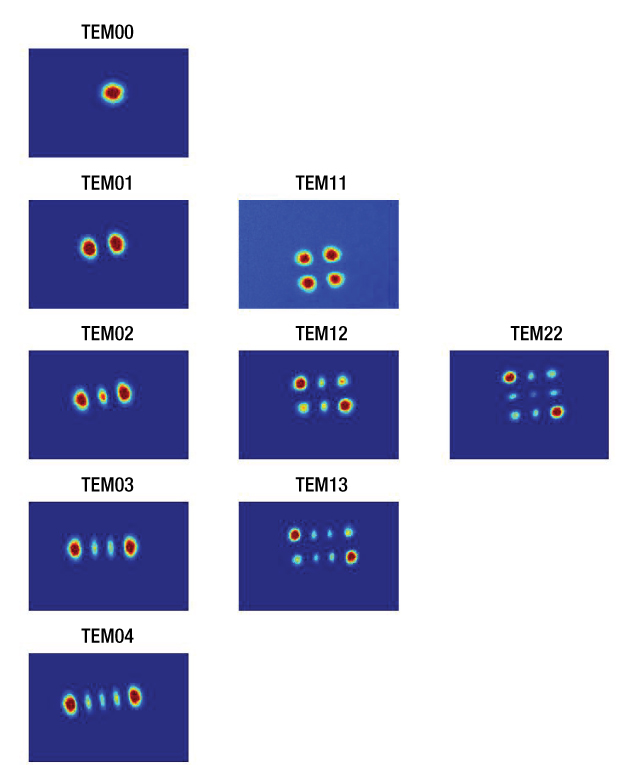
Figure 42A 低次TEMモードの空間モード構造。図は「Further Development of NICE-OHMs」から再現しています。2
ファブリペロー干渉計の最も一般的な構成は、高反射ながら一部を透過する2枚の球面ミラーを向かい合わせた共振器です。このタイプの共振器は以下の一連のパラメータによって特徴づけられます。
- 共振器の長さまたはミラーの間隔:L
- 入射側ミラーの曲率半径:R1出射側ミラーの曲率半径:R2
- 入出射および出射側ミラーの透過率:t1,2、反射率:r1,2、損失係数t1,2 + r1,2 + l1,2 = 1を満たしながら相互に関連)
入射側のミラーを通過して共振器に入った光波は、ミラーの反射によって2つのミラー間を何度も往復します。この間、光波には強め合う干渉と弱め合う干渉が生じます。強めあう干渉は光波を増強し、共振器内の電界を大きくします。これは、定在波が共振器ミラー間に形成される場合に起こり、その時、共振器の長さLは波長の半分の整数倍qλ/2に等しくなっています。この基準を満たしていない波長は共振されず、干渉を受けて弱まっていきます。
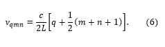
近軸波動方程式の一般的なガウシアンビームの解を仮定することにより、下記の周波数νqmnのみが共振器内に存在できることを示すことができます。1
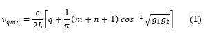
ここで、q、m、nはモード数で、0以上の整数となります。cは光の速さです。共振器のgパラメータg1,2は下記の式で求められます。

ここで凹面ミラーに対してはR1,2、凸面ミラーに対してはR1,2 < 0となります。これらの周波数は、m,n次のTEMモードまたはエルミート・ガウシアンモードと呼ばれ、通常TEMm,nで表されます。モード数mおよびnは横モードに関連付けられ、光軸に垂直な強度パターンを表しますが、qは縦モードに対応します。m = n = 0のTEM00モードは、基本TEMモードまたは縦モードと呼ばれ、m,n > 0のTEMモードは、高次TEMモードと呼ばれます。Figure 42Aでは、さまざまなモードにおける空間強度パターンを示しています。インデックスmおよびnは、それぞれ垂直方向および水平方向のノード数に対応します。近赤外領域の光の場合、パラメータqは106のオーダーとなります。共振器のgパラメータはいわゆる安定性基準によく使われます。共振器は、そのgパラメータが0 ≤ g1g2 ≤ 1の条件を満たしているとき共振器は安定していると言われます。1
ファブリペロー干渉計の透過スペクトル
Click to Enlarge
Figure 42B ミラーの反射率が99.7%、80%、4%ファブリペロー干渉計のモードスペクトルはそれぞれ青、赤、緑の曲線で示されています。 反射率99.7%は、1.5 GHzのFSR(フリースペクトルレンジ)を有するSA200シリーズを使用した時の値です。反射率4%は、平行する2枚のガラス面の間の反射から発生した典型的な「フリンジ効果」を示します。
光が基本TEM00モードに一致する空間モードの場合(つまり、ガウシアンビームの波面がミラー表面と完全に一致し、入射ビームが共振器の光軸にアライメントされている場合)、高次モード(m,n > 0)は発生しません。共振器の透過スペクトルは、パラメータqの値によって互いに異なるTEM00モードのみで構成されています。2つの連続したTEM00のνq00およびνq+1 00は共振器のFSR(フリースペクトルレンジ)と呼ばれ、下記の式で表されます。

この式は、2つのミラーで構成されるすべての線形共振器に適用されます。モードqから離調した周波数q, Δq = ν-νqに対する共振器の伝送強度Itは有名なエアリの公式3で求めることができます。
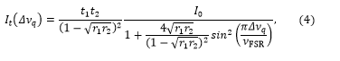
ここでI0は機器に入射する光の強度です。それ以外の値は上記と同様です。Figure 42Bは、ファブリペロー干渉計の典型的な透過スペクトルを示しています。上の式をもとに、オンレゾナンスでの透過Tcresは下記の式で表されます。
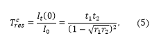
これにより、オンレゾナンスでの透過はミラーの透過率だけでなく、反射率と損失係数にも依存することが明らかになります。すべてのミラーの係数はt1,2 + r1,2 + l1,2 = 1の数式によってお互いに関連づいています。r1,2のセットに対して最大の透過率を得るために、吸収損失は可能な限り低く保たれています。
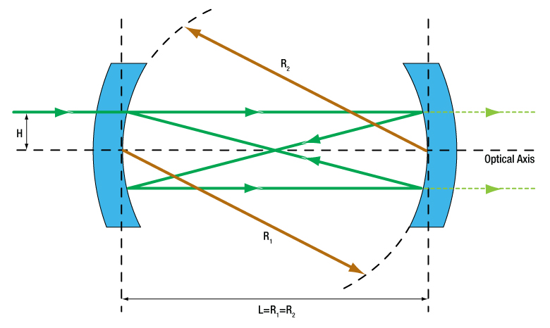
式(1)、(2)から、高次横モードの位置はミラーの間隔Lおよびミラーの曲率半径R1,2に大きく依存することがわかります。2枚のミラーの半径が等しい場合(R1 = R2 = R)や、ミラー間の距離がミラーの径と等しい場合( L= R)は特殊なケースとなり、共振器は共焦点共振器と呼ばれます。Figure 42Cは、光軸との距離がHで光軸と平行に共振器に入射するビームの典型的な光線追跡を示しています。 当社のすべてのファブリペロー干渉計はこのような共焦点干渉計の設計がベースになっています。この構成では、上の式(1) を次のように簡略化できます。
この式から2つの重要な結論を導き出すことができます。まず、すべてのモードは縮退しています。つまり、基本TEM00モードと同じ周波数を共有する高次のTEMモードが存在します(例えば、TEMq' 00, TEMq'-1 02, TEMq'-1 11, TEMq'-1 20, TEMq'-2 40, TEMq'-2 31, TEMq'-2 22, …はすべて同じ周波数を共有しています)。次に、スペクトルは規則的な等間隔モードの構造を示し、2つの連続するモード間の間隔はc/4Lで表されます。空間モードマッチングのために特別な注意が払われなければ、高次モードの圧縮はほとんど起きません。その結果、2つの連続した基本モード(TEMq00とTEMq+1 00)の間にいくつかの高次モードが存在し、モード間の間隔が等しいことにより、FSRがc/4Lと等しく見えてしまいます。高次モードの存在を説明するために、当社のファブリペロー干渉計のFSRに指定されたすべての値は、いわゆる共焦点フリースペクトルレンジνFSR,conf = c/4Lを参照しています。Figure 42Dの矢印はνFSRとνFSR,confの違いを強調しています。 共振器の光軸に沿った注意深いアライメントと、入射光のほぼ完全な空間モードマッチングにより、スペクトル内のほかのすべてのモードを消すことができます。Figure 42Dは、ほぼ完全なモードマッチングの構成を示しています。高次モードもまだ存在していますが、基本モードよりも小さくなっています。アライメントをさらに調整すると、最終的にはスペクトル内にあるほかのすべてのモードが識別されます。
Click to Enlarge
Figure 42C 共焦点ファブリペロー共振器の概略図。径R1 = R2(茶色の矢印)のミラーは、ミラーの半径に等しい距離Lだけ離れています。緑の実線は高さHで共振器に入る軸外入射ビームの光線追跡です。黄緑色の点線は2枚目のミラーを透過したビームを示しています。1枚目のミラーを透過した光は図に表示されていません。
Click to Enlarge
Figure 42D ほぼ完全な空間モードマッチングを有する共焦点共振器のスペクトル。基本モードのみが励起されると、ほかのモードはすべて消滅します。TEMqmnのラベルは、特定の周波数に含まれる1つのモードのみを示します。すべてのモードは縮退しており、本文で説明されているように、同じ周波数を共有する他のモードがあります。
フィネスとモード幅(分解能)

Click to Enlarge
Figure 42E 2つのローレンツ曲線のピークがFWHMだけ離れている場合、それらは分解可能なレイリの基準を満たします。
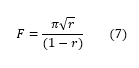
ファブリペロー干渉計の性能は、ミラーの反射率に大きく依存しますa。低反射ミラーは、より広い透過ピークを生成しますが、高反射ミラーは、より狭い透過ピークを生成します。ミラーの反射率は、干渉計の透過スペクトルの識別性能に大きな影響を与えます。ファブリペロー干渉計において、FSR(フリースペクトルレンジ)以上に重要な2つの値はフィネスとモード幅です。同一の反射係数rを有するミラーのフィネスFは、下記の式で求めることができます。
共焦点干渉計の場合、フィネスを次のように表わすと便利な場合があります。

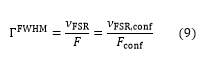
フィネスが高い干渉計は、フィネスが低い干渉計よりも狭い透過ピークを生成します。つまり、フィネスが高くなると干渉計の分解能が向上し、近接した透過ピークをより識別できるようになります。レイリ基準(Figure 42E参照)によると、ピークが各ピークの半値全幅(FWHM)で分離されている場合(ΓFWHMで示します)、2つの同一のローレンツ曲線を識別可能です。FWHMモード幅は分解能とも呼ばれ、下記の式で共焦点共振器のフィネスとFSRに関連していることが示されます。
これは、識別される2つのピーク間の最小許容間隔の基準値です。例えば、FSRが1.5 GHz、フィネスが250の干渉計のFWHMは6 MHzであるため、ピーク値が少なくとも6 MHz離れていれば、透過スペクトルの特性を識別することができます。可視光の場合、これはおよそ10 fm(10-14 m)の波長分解能に相当します。
当社では1550 nmで反射率99.9969%の結晶コーティングミラーをご用意しています。これは反射係数0.99999またはフィネス314,158に相当します。これらの結晶コーティングミラーを使用した干渉計では約4.8 kHzの分解能が得られることになり、これは上で例示した同じ1.5 GHzのFSRを有する干渉計よりも4桁ほど鋭い信号が得られることになります。
フィネスに関する追加考察
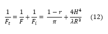
測定して得られたフィネスには、ミラー反射率フィネス(上記ではシンプルにFで表されています)、ミラーの表面品質フィネス( FQ)、ミラーの照明条件(ビームアライメントと直径)依存フィネス(Fiといういくつかの寄与因子があります。システム全体のフィネス(Ft)は次の式4で求められます。
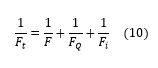
多くの場合、反射フィネス(式8)が実効的なフィネスとして使用されますが、これは他の要因が無視できる場合に限ります。当社の干渉計は、適切な照明で操作する場合、反射フィネスが支配的になります。b
数式(10)の第2項にはFQが含まれていますが、これはミラーの表面の凹凸を表わす数値で、スペクトルの左右対称の幅の広がりを意味します。このような凹凸があると、ビーム位置により光路長がばらつき、ピーク形状が不明瞭となります。共振器ミラー基板の製造工程では、共振器に関して当社が指定している総フィネスの仕様値と比較してFQの影響が無視できるほど小さくなるよう工夫がされています。つまり、基板の表面形状がフィネスの制限要因になることはありません。
ビーム径が拡大するにつれ、また入射ビームの光軸からのオフセットが大きくなるにつれ、数式(10)の最終項の照明フィネスFiが干渉計の分解能を悪化させます。フィネスがFiの項に制限される時、測定ピークは非対称となります。この非対称は、軸上の光線と軸外の光線の光路長の差に起因し、ミラー間隔が異なるため、最大透過基準を満たさなくなるという結果をもたらします。
Fiによる光路長変動の影響を定量化するために、理想的な単色入射、単位振幅を有する波長のデルタ関数、光軸と同軸にファブリペロー型共振器への入力、光線半径がaである光を想定します。光が干渉計にH = +eの位置で入射したときに、eがゼロではないが無限小の場合、透過スペクトルの差は最小限になります。一方で、H = +a の位置で光が共振器に入る時、透過出力スペクトルはシフトします。これは共振器の光路長が概算でa4/R3短くなるからです。入射光線の強度が均一だとすると、透過スペクトルは光路長のシフトの影響で、強度が均一かつ広がって見えます。結果として、波長のデルタ関数によって、FWHMが H4/R3の出力ピークが生成されます(Ref. 6参照)。
Click to Enlarge
Figure 42F 式(12)を使用して、ファブリペロー干渉計SA200およびSA210におけるビーム径2Hと総フィネスFt の関係を示したグラフ。フィネスは633 nmの波長λで計算しています
Fi のみが総フィネスに大きく影響すると仮定すると、上記の理想的な入射光線の場合には、Fiを計算するために数式(9)を用いることができます。FSRの代わりにλ/4、そしてFWHMの代わりに(H4/R3)を代入すると下記の数式が得られます。

1つの縦モードから次のモードに変化するために、共振器がλ/4拡大することを考えれば、FSRにλ/4を代入する理由がわかります。実際のスペクトル分布を持つ入射光線の場合は、このようなシフトが連続的に起きていると考えられます。なお、シフトは常に一方向である点にご注意ください。このためにビーム径が大きすぎたり、アライメントが悪い場合には、非対称であったり、広がったスペクトルが観察されます。
高反射ミラーを使用した場合の総フィネス(r ≈ 1)は式(10)を用いて求められます。この式にはFおよびFiから受ける大きな影響も含まれています(注:Fqが Ftに与える影響はごくわずかであるとみなしています)。
式(12)によって、ファブリペロー干渉計の総フィネスに対するビーム径の影響が予測できるため(一般的に予測値は大きくなっています)、いくつかの仮定を行ってみました。まず、ビーム径とミラー径が等しいと仮定します。実際には、ビームの直径は通常、ミラーの直径よりも大幅に小さく、球面収差は小さくなります5。次に、光が限りなく小さなウエストサイズに集光される場合を仮定します。 単色光の場合でも、最小ウエストサイズは回折によって制限され、マルチモードの用途では、焦点でのウエストサイズが非常に大きくなることがあります。Figure 42Fは、キャビティ長がそれぞれ50 mmと7.5 mmのファブリペロー干渉計SA200およびSA210について、633 nmにおける式(12)を表しています。このグラフの軌跡は、反射率フィネスがSA200では250、SA210では180であると想定されていますが、この数値は干渉計に使用されるミラーの典型値です。
キャビティリングダウン時間とキャビティ内電力の蓄積
光波は共振器内を何度も往復するため、光は一定時間内部に蓄積され、入射側または出射側のいずれかのミラーに当たる際に、そのエネルギのごく一部が漏れます。つまり、光波には共振器内での一定の寿命があります。この寿命はキャビティリングダウン時間またはキャビティ蓄積時間τcavと呼ばれ、下記の式で表されます。
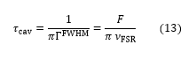
この式からτcav が増加すると共振器のフィネスも増加することがわかります。つまり、フィネスおよびミラーの反射率が高くなるほど、光が増幅器内に蓄積される時間が長くなります。同様に、もう1つの重要な数量はいわゆる共振器内電力の蓄積で、共振器内強度 Icの比および下記の入射強度によって定義されます。
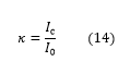
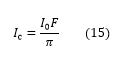
入射強度は、インピーダンス整合共振器(つまり、オンレゾナンスでの反射を消滅させる)ではF/π で求められます。これは下記の式によって内部共振器と関連付けられます。
共振器内に保存されるパワーがフィネスとともに増加するという事実は、高い入射パワーを持つビームをファブリペロー干渉計で評価する場合に留意する必要があります。
スペクトル解像力とエテンデュ
干渉計のスペクトル解像力はスペクトル分解能を定量化する基準であり、レイリ基準の拡張です。スペクトル解像力SRは下記の数式で表します:

ここで ν は光の周波数、λ は波長です。共焦点ファブリペロー干渉計では SR を下記の数式で求めることができます:

ここで、Fは干渉計のフィネス、Rはミラーの曲率半径、λは波長です。しかしながら干渉計が走査モードであるときに、干渉計がこの最高性能を達成するには、ディテクタの開口が限りなく小さくなる必要があります。開口が大きくなるにつれて、スペクトル分解能は低下します。スペクトル分解能と干渉計のエテンデュとのバランスの最適化が求められます。エテンデュ(U)は、干渉計の集光力を表す数値です。光源がレーザである場合、エテンデュによって干渉計とレーザ光線のアライメントのトレランスがわかります。エテンデュとは、許容される最大の立体角(Ω)と許容される最大開口の面積(A)との積で定義されます。共焦点システムにおいてエテンデュは下記の数式で求められます:

ここで、Fは干渉計のフィネス、λは波長、Lはミラー間の間隔です。干渉計を適切に使用するには、分解能とエテンデュのバランスを保つ必要があります。適切な数値でバランスを保つには、スペクトル分解能が70% (0.7*SR) となるまでミラーの開口を増大させます(Ref. 4)。この条件では「理想の」エテンデュはπ2λR/Fとなり、この時のRはミラー半径となります。
一般的な用途例を含む、当社のファブリペロー干渉計の詳細についてはこちらをご覧ください。
参考文献
- P. W. Milonni and J. H. Eberly, Lasers (John Wiley & Sons, Inc., 1988) p. 302.
- P. Ehlers, Further Development of NICE-OHMS, Ph.D. thesis, Umeå University, Sweden, 2014.
- D. Romanini et al., in Cavity-Enhanced Spectroscopy and Sensing, edited by G. Gagliardi and H.P. Loock (Springer, 2014), Vol. 179, Chap. 1, pp. 1 - 60.
- M. Hercher, "The Spherical Mirror Fabry-Perot Interferometer," Applied Optics, vol. 7, no. 5, pp. 951 - 966, 1968.
- J. Johnson, "A High Resolution Scanning Confocal Interferometer," Applied Optics, vol. 7, no. 6, pp. 1061 - 1072, 1968.
- W. Demtröder, Laser Spectroscopy, Vol. 1: Basic Principles, (Springer, 2008) p. 152.
脚注
- 光路長および、光路長から得られるFSR(フリースペクトルレンジ)、フィネス、モード幅は、干渉計の光軸からのビームオフセットhに依存します。つまり、最適な性能を得るためには、ビームを光軸に正しくアライメントする必要があります。また、干渉計に当たるガウシアンビームの曲率半径は、この反射面となるミラーの曲率半径と等しくなければなりません。ビームを適切にコリメートすることで、ファブリペロー干渉計ページの「アライメントガイド」タブ内のレンズに関する推奨事項に従って十分な性能を得ることができます。
- 当社のすべてのファブリペロー干渉計の反射コーテイングは、 Fの最小値が、各モデルの全動作波長範囲において最小の指定フィネス仕様値の1.5倍より良くなるように設計されています。
当社の走査型ファブリぺロー干渉計は幅広い用途にお使いいただくことができます。そのうちの3つの使用例について以下でご紹介いたします。線幅の測定例は、シングルモードのスペクトルを放射するレーザ、または非重複モードのマルチモードレーザからの個別モードに有効です。
使用例1:走査によるレーザーモードの線幅の測定
「校正」タブで説明されているように、レーザーモードの線幅の測定は、オシロスコープを使用して、時間軸の校正、モードの拡大、半値全幅(FWHM)の測定をすることで実施できます。ただし、この測定を行う際に考慮すべき型が3つあります。それらは、下表のように、レーザ線幅ΓFWHMlaserとファブリペロー共振器モード幅ΓFWHMの比によって規定されます。
| Regime | Comments |
|---|---|
| ΓFWHMlaser >> ΓFWHM | 操作に適切なモードです。 ピークの形状はレーザの線幅によって決まるため、測定されたFWHMはレーザーモードの幅です。共振器のモード幅がもたらす影響はごく僅かです。 |
| ΓFWHMlaser ≈ ΓFWHM | オシロスコープから抽出されたFWHMは、ピーク形状と共振器モードのコンボリューションです。真のレーザ線幅を決定するには、デコンボリューション手順が必要です。 |
| ΓFWHMlaser << ΓFWHM | ピークの形状は共振器モードの幅によって決まるため、測定されたFWHMは共振器モードの幅です。この場合、レーザ線幅を評価するためにはより高フィネスのファブリペロー共振器を選択する必要があります。もう一つの方法として、使用例2で説明する、いわゆるサイドオブモードテクニックを使用して線幅を推定することができます。 |
使用例2:サイドオブモードロックによるレーザーモード線幅の決定
レーザ線幅の推定値は、ファブリペロー共振器モードの傾きを把握し、レーザーモードと共振器モードが互いにオフセットしているときに発生する強度変動を測定することで決定できます。この手法を用いる場合、レーザ線幅がファブリペロー共振器のモード幅よりも大幅に小さい必要があります。例えば、通常の方法では、レーザ線幅が500 kHzの時、分解能が7.5 MHzのSA200を使用して線幅を決定することはできません。こちらのセクションで説明する測定方法は、ピュアDC出力を行わないコントローラSA201では実行できないことに注意ください。代わりに、一定かつ安定したDC出力が可能な低ノイズPZTドライバ(例えば シングルチャンネルの開ループピエゾコントローラMDT694B)を使用する必要があります。
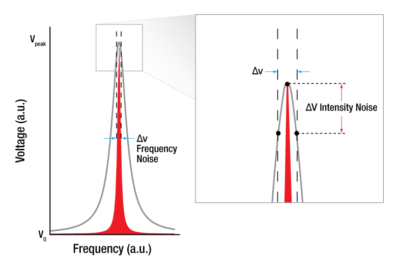
下の図は、この手法で使用される強度ノイズを示しています。図1では、レーザ(赤)がファブリペロー共振器モード(グレー)の中心にくるようにチューニングされています。レーザには、FWHMによって定義される周波数ノイズΔνがもともと存在し、これにより、干渉計を透過する光の強度が変動します。レーザのFWHMからファブリペロー共振器モードのプロファイルまでの黒い点線は、周波数の変動(青い矢印)が強度に僅かなノイズ(赤い矢印)をもたらすことを示しています。図2に示すように、同量の周波数ノイズΔνに対して、共振器モードの中心からずれてチューニングされたレーザは、より大きな強度ノイズΔVを生成します。
Click to Enlarge
図1:周波数-ノイズ間の振幅変換。レーザが共振器モードの中心にチューニングされている時、周波数ノイズΔν (青い矢印)は、少量の強度ノイズΔV (赤い矢印)を生成します。ファブリペロー共振器に記載されているグレーのピークは共振器モード、赤いピークはレーザモードをそれぞれ示しています。

Click to Enlarge
図2:周波数-ノイズ間の振幅変換。レーザが共振器モードの中心からずれてチューニングされている時、図1と同じ周波数ノイズΔν (青い矢印)は、より大きな強度ノイズΔV (赤い矢印)を生成します。グレーのピークはファブリペロー共振器モード、赤いピークはレーザーモードをそれぞれ示しています。
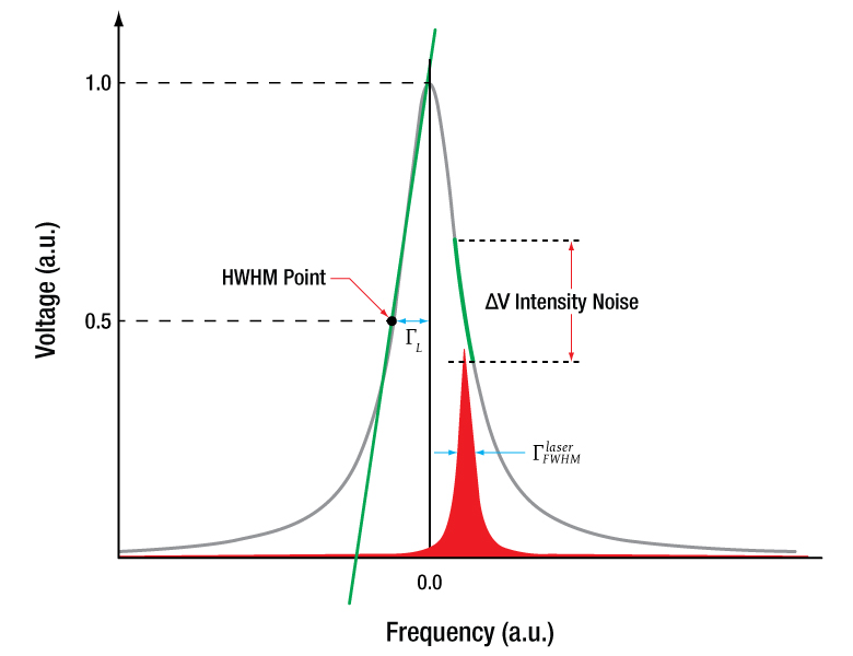
レーザはファブリペロー共振器モードの中心からずれてチューニングされているため、電圧変動を共振器モードの勾配に関連付けることで線幅を推定することができます。図3はこの関係を視覚的に示しています。緑の線は、この計算によって等しいと想定される2つの勾配を示しています。ファブリペロー共振器モードではローレンツ曲線がみられます1。
Click to Enlarge
図3:ローレンツファブリーペロー共振器モードプロファイルの勾配と強度ノイズの関係。グレー、赤、緑の線はそれぞれ共振器モード、レーザーモード、勾配を示します。青い矢印は周波数ノイズ ΓFWHMlaser(図2のΔν )、赤い矢印は強度ノイズΔVを示します。

ここで、ΓLはモードの半値全幅(FWHM)、Δνはν-νqです。このスペクトルに1次導関数を用いると、HWHMポイント(図3のポイント)での共振器モードの勾配γ’q,Lは下記のようになります。

ファブリペロー共振器のΓL は、 ΓFWHM/2によって計算できます。これについては「チュートリアル」タブの式(8)をご参照ください。また、当社のすべてのファブリペロー干渉計の仕様にも記載されています。レーザの線幅(FWHM)ΓFWHM laserは、下記の式で求められます。

ここで、ΔVはオシロスコープの読み取り値から決定できる強度の変化、γ'q,L(-ΓL)はHWHMポイントにおける共振器モードの勾配、係数Cは、測定値に存在するノイズタイプのピーク-ピーク値とRMS(二乗平均の平方根)の関係の推定値を表します。ホワイトノイズの場合、係数Cはsqrt(2)であることがわかります。係数Cによりレーザの線幅が過大評価されるため、計算された線幅が実際の物理値よりも小さくなることはありません。
使用例3:モードスペクトルの測定
この走査型ファブリペロー干渉計は、高解像度のスペクトルアナライザとして、レーザの性能をモニタする用途にご使用いただけます。製造現場では、製造中に使用して、サイドモードが十分に抑制されているか、または望ましい変調度が得られるかを確認することができます。また、教育現場でもご使用いただけます。具体的には、HeNeレーザのウォーミングアップ中にHeNe共振器モードを観察したり、フリースペクトルレンジ(FSR)やHeNe内の共振器の実効長などの特性を決定したりすることができます。
レーザーのモードスペクトルよりもFSRが大きい干渉計を選択することの重要性を示すために、下の図4および図5では、ランダム偏光レーザHNL100RBによるHeNeスペクトルのシミュレーション結果と、干渉計SA210-5BおよびSA200-5Bによる検出結果の違いをを示しています。約1.3 GHz幅の利得プロファイルを有するHeNeレーザのスペクトルの検出にはSA210-5Bがより適しています。そこでは、ファブリペロー共振器の10 GHz間隔で連続する2つのモードによってスペクトルが検知されています。レーザの各モードはグレーで表示され、図の赤い点線はレーザの利得プロファイルを示しています。赤い点線は利得プロファイルのエンベロープ部を強調するために含まれていますが、スコープには表示されないことにご注意ください。これに対し、1.5 GHzのフリースペクトルレンジを有するSA200-5Bで見ると、レーザのプロファイルは重なります。利得プロファイルを示す線はオシロスコープ上に表示されないため、個々のレーザースペクトルを隣接するスペクトルから区別することは困難です。これは利得プロファイルが走査型ファブリペロー干渉計のフリースペクトルレンジと同程度であるためです。図4の黒い点線は、有効なゲインの閾値を示しています。この閾値を超えるモードのみが発振し、スペクトルに表示されることにご注意ください。レーザがウォームアップすると、HeNe共振器が熱膨張により膨張し、共振器の共振周波数が変化します。その結果、利得プロファイルより低次のモードは移動し、中心に向うほど強くなり、閾値を下回ると消滅します。

Click to Enlarge
図4:約1.3 GHzの利得プロファイルでHeNeレーザのモードスペクトルを検出するSA210-5Bの2つの連続モードを示すシミュレーション。利得プロファイルよりも大幅に大きい10 GHzのFSRでは、レーザースペクトルは重なりません。赤い点線、グレーの実線および黒い点線は、それぞれ利得プロファイル、縦モードおよび利得閾値を示しています。
Click to Enlarge
図5:約1.3 GHzの利得プロファイルでHeNeレーザのモードスペクトルを検出するSA200-5Bの2つの連続モードを示すシミュレーション。1.5 GHzのFSRでは、観測されたレーザースペクトルが互いに重なり、情報を抽出することが困難になります。赤い点線、グレーの実線および黒い点線は、それぞれ利得プロファイル、縦モードおよび利得閾値を示しています。
参考文献
- N.Ismail, C.C. Kores, D. Geskus, and M. Pollnau,"Fabry-Pérot resonator:spectral line shapes, generic and related Airy distributions, linewidths, finesses, and performance at low or frequency-dependent reflectivity," Optics Express, vol. 24, no. 15, 2016.
ソフトウェア
バージョン1.3.0 (2025年4月23日)
このソフトウェアパッケージには、走査型ファブリペロー干渉計用コントローラのためのソフトウェアとThorlabs Device SDKが含まれています。
| Minimum Computer Requirements | |
|---|---|
| Operating System | Windows 7 64-bit (or later) |
| Other Software | Microsoft .NET 4.5 (or later) Microsoft Visual Studio for SDK Demo |
制御ボックスSA201B用ソフトウェア
当社では、ファブリペロー干渉計用コントローラSA201BをPCでリモート制御するためのWindows GUIアプリケーションソフトウェアをご用意しています。デバイスにはソフトウェア開発キット(SDK)も付属しているため、ファブリペロー干渉計用コントローラをほかのアプリケーションに組み込むことも可能です。
| Posted Comments: | |
user
(posted 2025-03-14 09:55:07.067) Hello, would it be possible to purchase the cavity mirrors of the SA200-3B separately?
Thanks! eeklund
(posted 2025-03-17 02:58:00.0) Thank you for reaching out to Thorlabs! We will contact you via email to discuss your application. Steven Huang
(posted 2025-02-12 16:48:44.623) To whom it may concern,
Do you have a module that could operate to FSR=20GHz? acanales
(posted 2025-02-13 07:11:47.0) Thank you for reaching out! Our SA series is designed with a free spectral range (FSR) of 1.5 GHz and 10 GHz. However, if you need a higher FSR, our FPQFA and FPQSA series offer an FSR of 30 GHz. I have contacted you directly to discuss the specific requirements of your application. user
(posted 2025-01-27 20:23:54.64) We are looking to characterize an EOM with a frequency of 9.2 GHz using the SA30-95 FP cavity from Thorlabs. According to Thorlabs, the SA30-95 model specifies a scanning range of 2.6 V per FSR.
Could you kindly provide clarification on the following points:
1. What is the maximum scanning range of this cavity (total ramp voltage to frequency range)?
2. Would this cavity be suitable for characterizing an EOM with a frequency of 9.2 GHz?
Thank you in advance. Your guidance will help us move forward efficiently.
Best regards,
Poonam Yadav acanales
(posted 2025-01-28 07:08:18.0) Thank you for reaching out to us!
1. The piezos in SA30 have a max distance range of 9.5 µm ± 15% @150 V.
2. If would like a setup similar to the one described in our website (https://www.thorlabs.com/newgrouppage9.cfm?objectgroup_id=3918&tabname=lab%20facts) with a modulation of 9.2 GHz, please consider a Fabry Pérot with FSR of at least 10 GHz (SA210). It would be even better to consider the FPQFA since it has a higher FSR of 30 GHz.
I have contacted you directly to discuss your application in detail. Yi Fang
(posted 2025-01-09 01:34:35.337) Dear Thorlabs,
It can be observed that the distance between 1st peak and 2nd peak is not the same as between 2nd peak and 3rd peak in Fig.3 in the "calibration" tab. How to avoid the effect of the small non-linearity caused by hysteresis of piezo-electric actuators
Best,
Fang Yi fnero
(posted 2025-01-13 02:04:28.0) Thank you for your question. There will be a small difference in the distance between the peaks, as you point out. To limit this error it can be an advantage to take the average of two distances between the peaks. We have reached out to you directly to discuss your application more in detail. user
(posted 2024-12-27 21:04:04.63) Hi,
We need to characterize EOM of 9.2 GHz. What will be the better option for us either 10GHz or 1.5 GHz FSR?
Thanks in advance! srydberg
(posted 2024-12-30 03:49:43.0) Hi, thank you for your question! We have contacted you to discuss your application. user
(posted 2024-10-24 16:56:42.467) Hello,
I was wondering if it was possible to order/have a 10GHz SFPI with an interchangeable detector. I can see that it is fairly simple with the 1.5GHz design, but not a higher FSR model.
In addition, it might be a stretch to ask if it is possible to facilitate higher FSR with comparable spectral scanning speeds. A good example would be a 15GHz confocal SFPI that would take no longer than 15ms to scan its range.
Thanks. acanales
(posted 2024-10-29 04:46:28.0) Thank you for contacting Thorlabs! The detectors on all the Fabry-Pérots can be changed by unscrewing them. The scanning range and speed depend on the controller you use. We have contacted you to discuss custom options for your application. user
(posted 2024-10-22 23:06:06.077) Hello,
I am looking for high-extinction narrow-band notch filters. Does the reflection dip of these FP interferometers have high extinction as well (e.g. >40 dB)? eeklund
(posted 2024-10-23 09:58:20.0) Thank you for contacting us! We have contacted you directly to further discuss your application. Richard Spencer
(posted 2024-09-12 14:44:34.323) For the Scanning Fabry-Perot Interferometers, how suspectable are these to vibrations? Would a floating table be necessary or even recommended? acanales
(posted 2024-09-13 05:45:05.0) Thank you for contacting Thorlabs! A floating table is not necessary for our Fabry-Pérot interferometers. A sturdy table with strong mechanics will suffice. For increased mechanical stability and easier alignment, you can use XT66SD or XT95SD rails instead of mounts with long posts. We have contacted you to discuss your application further. Jin Zhao
(posted 2024-05-13 15:34:33.34) Hello Thorlabs, I would like to use the SA200-5B as a filter. If spatially collimated light is input, can the SA200-5B output collimated light filtered within my wavelength range of 590-595nm? Is the spacing between filtered modes approximately 10pm? And does the transmittance of the filtered modes approach 100%? Best regards, Jin. user
(posted 2024-02-15 10:00:13.447) What is the maximum frequency at which I can drive the piezo? acanales
(posted 2024-02-16 06:11:16.0) Hi Jelte, thank you for contacting us! We have not tested the maximum driving frequency since it will depend on the device and voltage range. The measurements shown in the manual and the website are taken with frequencies between 5-50Hz. You can contact Tech Support to discuss your application. Jens LaSSEN
(posted 2024-02-07 16:08:28.53) would there be a chance to use my own optics in the SA200's
would there be an upgrade path to a 300MHz scanning FPI? acanales
(posted 2024-02-09 07:22:25.0) Thank you for your feedback! We have reached out to you to discuss your application more in detail. Soumya Chakraborty
(posted 2023-12-15 09:52:17.483) Hello Thorlabs,
For the product SA200-5B, could you please tell me the dynamics range of the sensitivity of the photodiode used?
Best regards,
Soumya fnero
(posted 2023-12-22 02:21:26.0) Hello Soumya, thanks for reaching out to us. The photodiode used in the SA200-5B is SM05PD1B, the specification for this photodiode can be found on the photodiode page. Jeremie M
(posted 2023-10-31 15:24:53.22) Hi, suppose I want to use the SA210-3B to make spectra of a laser whose centre wavelength can be set between 500 and 502 nm. In that case, all I have to do is adjust the DC voltage, right?
So it's conceivable that a full spectrum could be produced with high resolution in the 350-535 nm range by adjusting the DC voltage? srydberg
(posted 2023-11-01 07:55:44.0) Hi, thank you for your question!
We have contacted you directly to discuss your application. Guanchen Peng
(posted 2023-10-20 16:38:20.42) Hi,
It is generally working very well, but I found it was not able to be scanned yesterday. I measured the input impedance, which turned out ot be 10ohm. Any suggestion on how to fix it?
Regards,
Guanchen srydberg
(posted 2023-10-20 08:12:34.0) Hello, thank you for contacting Thorlabs! We have contacted you directly to troubleshoot this issue. user
(posted 2023-09-27 11:31:05.693) We are currently trying to improve the transmittance of SA210-12B by matching the input light mode.
I have the following three questions
(1) Do the back surfaces of the two mirrors (the surfaces without reflective coating) each have the same curvature? Or are they flat? Also, what is the radius of curvature of the back surface of each?
(2) I would like to know the thickness of each of the two mirrors.
(3) What is the possible difference in reflectance between the two mirrors? fnero
(posted 2023-09-28 05:19:28.0) Thank you for contacting Thorlabs! We have reached out to you directly to discuss your application and answer your questions. Rachel Jones
(posted 2023-06-14 13:16:08.08) Hi thorlabs,
In the manual for the SA30-144 it suggests that removing the PD on the back of device can help aid in the alignment process. Could you please tell me what size allan key I need to remove the PD? I could not find this in the tecnical drawing. mkarlsson
(posted 2023-06-15 07:16:18.0) Hi Rachel, thank you for your question! The PD is not fastened with a hex screw but can be unscrewed by hand. The hex screw you might be referring to belongs to the aperture. Daniel Hickstein
(posted 2023-05-25 16:51:00.16) How fast can the piezo respond when used in this device? In a previous response to a similar question, soswald replied that the system uses 3 pieces of PC4WM in parallel, that the unloaded piezo response is 115 kHz, and the moving mass is 12 g. This is said to "slightly reduce" the resonant frequency.
Based on the equation on the "Operation" tab of the piezo page, the new resonant frequency is calculates as f' = f0 * sqrt(m/3 / (m/3 + M), where m is the mass of the piezo and M is the mass of the load. The mass of the piezo is not listed, but if I calculate its volume at 0.16 mL, so I'll assume it's mass to be 0.2 g. If I let M=4g, then I find that f' = f0 * 0.13. So, f' = 15 kHz.
A 15 kHz response seems reasonable, but I'm curious if I've done the calculations correctly, and if this agrees with lab measurements of these devices. Additionally, I'd argue that this is more than a "slight" decrease of the frequency response compared to the unloaded piezo. tberg
(posted 2023-05-29 04:45:31.0) Thanks for contacting Thorlabs! I have reached out to you directly to discuss this matter. user
(posted 2023-05-09 18:20:31.063) Hello, I recently used your wonderful SA210-8B products, but accidently disassemble a part of it. When I try to replace the photodetector, not the SM05 thread but the adjacent one was opened. (A round metal plate with holes and an O-ring was hanging on wires connected to the piezo) Closing it up again was not that hard, but I noticed the wires just block the hole for transmitted beam when the cavity was reassembled. I try hard to properly organize that wires, but every attempts were failed. Can you advise how I could reassemble the cavity? Thanks. tberg
(posted 2023-05-09 09:19:53.0) Dear Haejun, Thank You for contacting Thorlabs! The fact that incorrect thread interface accidentally opened upon removal of the detector assembly is clearly a manufacturing error on our part and I apologize for that. I have reached out to you directly on how to solve the problem via RMA. Also, we have taken steps and measures to minimize the risk that this happens again. Andres Forrer
(posted 2023-02-22 10:23:25.697) Could you provide us with the max. optical power allowed to enter the the SA210-12B. There is no information on this part. tberg
(posted 2023-02-23 08:27:47.0) Dear Andres, Thanks for your feedback! Max optical power allowed to enter the the SA210-12B is limited by saturation power of the photodiode used in this product. These are low power devices and typical saturation power is typically about 10mW. There is a large variance in this typical value due to wavelength dependency of the detector responsivity. I will reach out to you directly to discuss your application. Pingping Qiu
(posted 2022-09-13 11:32:36.563) 你好!近期从贵司购买了SA30系列干涉仪,想咨询几个技术问题:1.光源为半导体激光器,中心波长分别为894nm和795nm,针对这两波长,所需透镜能否推荐或定制;2.除了耦合空间光进行测试,是否有合适的接口,可以将经准直后的光束直接和FP干涉仪对接的方法. GUO LONG
(posted 2022-08-04 15:58:05.073) we found that we need to confirm if the low fitness CFBI can meet our system requirement or not. is that possible we apply sample for lab evaluation before purchase. xin yang
(posted 2022-07-05 12:17:08.817) 我想买这个FP的探测器 想咨询一下 jdelia
(posted 2022-07-06 10:08:47.0) Thank you for contacting Thorlabs. We will reach out to you directly regarding your application. Christopher Reilly
(posted 2021-11-11 04:42:22.34) Hello, what is the mechanical frequency response of the piezo actuator on the SA200-30C? soswald
(posted 2021-11-17 02:17:25.0) Dear Christopher,
thank you for your feedback.
Our scanning Fabry Perot Interferometers use 3 pieces of PC4WM piezos in parallel. The resonant frequency of these piezos is 115 kHz ± 10%, specified at no load. The moving mass is about 12 g which slightly reduces the resonant frequency. Please see 'Operation' tab on the piezo webpage for details:
https://www.thorlabs.de/newgrouppage9.cfm?objectgroup_id=61&pn=PC4WM Zeyun Peng
(posted 2021-11-08 15:57:46.273) Hello, we are trying to use SA201 and SA200-8B to measure the frequency drift of our 1092 nm laser. I would like to know how large the coefficient of thermal expansion of the cavity is and how large the long-term drift of the cavity is when it is drove by SA201 with 1x sweep expansion. Right now, I can stabilize the temperature of the cavity within 0.02 K. I observed a frequency drift of 400 MHz within 2 days, and our wavemeter, which is not quite reliable at 100 MHz level, shows that the drift caused by the cavity is within 200 MHz. But I hope to get a better idea of that. YLohia
(posted 2021-11-23 03:30:29.0) Hello, thank you for contacting Thorlabs. The thermal drift of the SA200-8B is typically -0.2 GHz/C. jens lassen
(posted 2021-04-23 19:18:44.853) (i) could you please tell me whether I can exchange optics sets on the SA210-5B to change wavelength coverage? (ii) Would you happen to have a manual / instructions for that? (iii) I would like to operate the SA210-5B in vacuum - would you happen to have a drawing for me that only shows the body? (iv) eventually I would like to reduce the FSR by inserting an invar spacer. Are there provisions for inserting a spacer, as was the case with the old Burleigh CF series or the Tropel CFPI's?
Thank you so much for your help,
Jens YLohia
(posted 2021-04-29 02:22:11.0) Hello Jens, due to the inherent design, mirror sets in the SA210 series are not interchangeable. The SA210 series is not vacuum compatible off-the-shelf. These may or may not be converted to suit low to medium vacuum applications after slight modifications. Support drawings and CAD models showing the body are available on our website. Due to the confocal design, cavity length is fixed so we do not offer spacers to alter the Free Spectral Range. Xu Liang
(posted 2020-11-15 14:29:16.027) Hello, I am encountering such a problem now. I use a broad source (Menlosystems C-Fiber) to reach the free space through a collimator (RC02FC-P01). After passing through the interferometer(SA200-12B), I want to couple the light to another collimator (RC02FC-P01) again, but the actual operation found that the transmittance is extremely low, not reaching 1% at all, and it cannot be coupled to the collimator. What is the reason? Is it the problem of alignment and installation, or the problem of not adding a lens, or that our interferometer can not be used in this way? I hope that there will be special technical support to contact me, thank you very much YLohia
(posted 2020-11-17 09:22:54.0) Thank you for contacting Thorlabs. This is likely due to a few factors -- you must align the system properly (this can take a while) and you also should use a focusing lens before the unit. Please also ensure that the iris in the unit is fully open once the system has properly been aligned. Additionally, the collimators/couplers are designed to focus collimated beams at a fixed distance. The FPI does not output a collimated beam from the detector port so the coupling efficiency into your fiber will also be quite poor, even with good system alignment. user
(posted 2020-10-12 14:43:21.037) 1. If I use this as a filtering cavity can I send light in from either direction? (noting from the cavity geometry suggests otherwise?)
2. What preferred polarization input does it require? YLohia
(posted 2020-10-16 09:22:39.0) Thank you for contacting Thorlabs. 1) You can send light in from either port (after removing the mounted photodiode). 2) There is no specific input polarization state requirement. Vladimir Zenin
(posted 2019-04-15 07:27:50.41) Hi,
I am wondering, can I use Fabry-Perot Interferometer as a spectral filter? I mean, for example as an input I have a nice fiber-coupled beam with spectral width of 10 nm (for example, 1440-1450 nm). With collimator it can be made nearly perfect Gaussian. At the output I need a Gaussian or fiber-coupled light with narrower spectra. I have spectrometer to measure precisely the wavelength, but need a filter. Can Fabry-Perot Interferometer be such a tunable filter? Or are there any better product in Thorlabs?
You might be interested in my source - it is broadband source SuperK Extreme, from NKT Photonics, equipped with SELECT filter (https://www.nktphotonics.com/lasers-fibers/product/superk-extreme-fianium-supercontinuum-lasers/, https://www.nktphotonics.com/lasers-fibers/product/superk-select-multi-line-tunable-filter/). At output I can get as narrow as 5-10 nm spectrum, and its central wavelength is tunable.
Thank you in advance, and happy Easter!
Best,
Vladimir YLohia
(posted 2019-04-17 11:07:22.0) Hi Vladimir, thank you for contacting Thorlabs. In principle, using an FPI as a spectral filter is possible. However, the Free Spectral Range of our high resolution Scanning Fabry-Perot Interferometers is as short as 10 GHz or 1.5 GHz depending on model (SA210 or SA200 series). In the wavelength plane, this corresponds to narrow wavelength bands 75pm or 11.25pm at 1500nm absolute wavelength. And filter bandwidth is as narrow as in the 7-70 MHz range (corresponding to 0.05-0.5pm). This means that the spectrum obtained by the Scanning Fabry-Perot will repeat itself periodically in either 75pm or 11.25pm wavelength bands and filter function is in the 0.05-0.5pm range due to the high resolving power of these instruments. So, filtering from these instruments would only be meaningful if your input signal is narrower than 75pm (or 11.25pm). Commercially available tunable Fabry-Perot filters typically have a Free Spectral Range in the 10 THz range (corresponding to ~100nm) and a bandwidth of a few hundred pm. julian.robertz
(posted 2018-12-11 14:12:51.273) Dear Support-Team
Tank you for the information in the alignment guide.
I have one question regarding the recommended beam size and lens for the FP interferometers you are mentioning in the table. The beam waist behind the lens is highly dependent on the beam waist in front of the lense. Which beam waist have you assumed to give these values? swick
(posted 2019-01-31 09:57:50.0) Thank you for your feedback. For example lenses with focal length 250 mm like LA1461-B or mounted version LA1461-B-ML will provide small enough waist well below recommended 600 µm for 2 mm diameter beam @ 812 nm on input. user
(posted 2018-11-01 15:23:01.95) Can you also provide the high finesse FP cavities (SA30-52) at other wavelengths? YLohia
(posted 2018-11-02 09:17:07.0) Hello, thank you for contacting Thorlabs. We may be able to provide this, depending on your requirements. Please email us at techsupport@thorlabs.com to request a quote for custom items. abc124771
(posted 2018-08-29 22:14:15.52) Can SA201 or SA201-EC be used to drive PC4FL? nbayconich
(posted 2018-09-11 01:17:30.0) Thank you for contacting Thorlabs. The SA201 is designed specifically for driving the piezos of our fabry perot devices. It is not intended to be a general purpose piezo driver. In order to drive the pc4fl actuator to it's full displacement you will need a driver that can supply 150 volts where as the SA201 provide 45 volts max output voltage at 15mA.
I would recommend looking into the BPC301 or MDT694 piezo controllers which can provide a much higher operating voltage and current. jean-michel.melkonian
(posted 2018-07-20 09:03:55.237) HI,
I have exactly the same question as geoffroy.aubry, about the piezo hysteresis. Not only that, but I also observe it on my setup.
We use the FPI to measure the frequency spacing between two modes of our laser source. We calculate the spacing as: Dvu = FSR_FP*(DT_laser/DT_FP), where FSR_FP is the Fabry-Perot FSR (10 GHz nominaly), DT_FP the time spacing between two resonance peaks of the FP (i.e. one FSR in time), and DT_laser the time spacing between the 2 resonance peaks due to the two longitudinal modes of our laser.
The problem is that DT_laser is not the same whether we are looking at the begining of the ramp or at the end, ie there is some dilatation.
Could you contact me to help me calibrate this effect? Thank you. YLohia
(posted 2018-07-23 09:36:52.0) Hello, while the voltage is a linear triangle or sawtooth curve, the cavity length is changed by piezoelectric actuator which will have some hysteresis. This is most exaggerated at the edges of travel, particularly when the direction of travel changes. The response between voltage and position will be most linear in the center of the movement. Due to this PZT hysteresis, the conversion between frequency space and time space varies over the scan of the PZT elements. In order to get the best possible accuracy, we recommend calibrating the time axis in the vicinity of the mode to be measured. In other words, when evaluating the width of a particular transmission peak, calibrate the time axis with the two immediate neighbors of the mode under measurement. abc124771
(posted 2018-05-25 03:13:21.513) Could you please give detailed specifications of the mirrors used for the cavity? Are those mirrors separately available? What are the reflectances and transmissions for the back side and front side of the mirrors? nbayconich
(posted 2018-05-29 09:01:06.0) Thank you for contacting Thorlabs. Yes, we can provide the mirrors of our fabry perot interferometers separately as a custom order item. Any custom or specials orders can be requested through techsupport@thorlabs.com.
The reflectivity of the mirror coating material is above 99% for the coating design range however the typical transmission through the fabry perot interferometer is about 10-20%, the loss is do from absorption in the mirror substrate and coating material after multiple reflections through the cavity. In theory with no absorption loss present the transmission would be significantly higher. I will reach out to you directly with more information about ordering our fabry perot mirrors separately. abc124771
(posted 2018-05-23 04:07:57.34) Can the 7.5mm FP be used to obtain fringes with a white light source? mmcclure
(posted 2018-08-13 10:59:52.0) Yes, it is possible to see fringes without using the drive electronics. You will have to open up the second iris all the way and remove the photodiode connected to the female SMA. The will allow the beam to leave the FPI housing and be projected on to your screen. In order to have good alignment, you will need to first set up your two alignment mirrors before the unit and make adjustments till you see fringes on the output. Once you see the fringes, adjust the z-position of your lens till you obtain optimal fringe contrast. abc124771
(posted 2018-05-14 23:29:51.337) In the 'Calibration' tab, in the example given, linewidth is found to be 4.7MHz, but the resolution for that paticular FPI is just 7.5MHz. If I'm not wrong, resolution is the least we can resolve any spectral line... then how can we measure a line of FWHM 4.7MHz using that particular FPI? YLohia
(posted 2018-05-16 08:39:42.0) We state that the SA 200 resolution is 7.5 MHz corresponding to Finesse = 200. The F=200 is a minimum spec, while the typical spec is F=250 corresponding to resolution = 6 MHz. The relation between finesse and resolution is defined
F = FSR/FWHM,
where F = Finesse, FSR = Free Spectral Range and FWHM = resolution.
Our finesse spec is set quite conservatively, so it's not unusual that we ship units with finesse in the 300-350 range. In the example on the web, a F=320 cavity is used (a random unit tested from stock) corresponding to 4.7 MHz resolution. abc124771
(posted 2018-05-14 02:39:32.15) The 'd' (50mm) is given as 'nominal distance'. So is this 'd' exactly the minimum distance between the two mirrors or the maximum? I mean when we apply voltage, does the distance between the mirrors increase from 50mm or does it decrease to an even lower value than 50mm? Or is it the average? If so, then what is the minimum and maximum 'd' achievable by applying voltage? And also could you please specify the sensitivity of the piezo, as in what is its V/mm rating? YLohia
(posted 2018-05-15 10:00:00.0) Hello, thank you for contacting Thorlabs. The nominal mirror separation d is 50mm with a ±0.1mm tolerance. The piezos used in the SA200 series have a displacement of 9µm for 150V. The SA201 Control box has a max voltage swing of 30V, so the maximum displacement is typically 1.8µm and, in most cases, the full 30V swing is not really necessary. Thus, the distance variation due to applied piezo voltage is typically on the ~1µm scale. unnati_a
(posted 2018-05-07 05:08:31.63) Is it possible to get just fringes with this instrument without scanning and all? I mean if I just want to display the fringe pattern on a screen for some purpose apart from scanning? What alignment precautions will have to be taken in that case, since we won't be using the controller and scope for alignment? YLohia
(posted 2018-05-31 08:59:02.0) Yes, it is possible to see fringes without using the drive electronics. You will have to open up the second iris all the way and remove the photodiode connected to the female SMA. The will allow the beam to leave the FPI housing and be projected on to your screen. In order to have good alignment, you will need to first set up your two alignment mirrors before the unit and make adjustments till you see fringes on the output. Once you see the fringes, adjust the z-position of your lens till you obtain optimal fringe contrast. aspindler
(posted 2018-04-11 12:46:49.307) Hello, I am wondering if your products are suitable for use in a vacuum. My company is interested in developing a space based system using an interferometer. Are your FPIs air spaced? I would assume they might just pop in a vacuum if they don't have a way to outgas. YLohia
(posted 2018-04-12 11:15:11.0) Response from Yashasvi at Thorlabs USA: Hello, thank you for contacting Thorlabs. The stock FPI's you see on our website are not suitable for vacuum use. What is the pressure/vacuum level you intend to use this at? The mirrors used in these are air-spaced, however. We could look into offering just the stripped invar cavity module without the outer housing. We would also have to use vacuum grease and vacuum compatible glue. I have reached out to you directly to discuss this further. user
(posted 2018-03-19 12:48:34.75) Hi guys,
Can i use a sawtooth voltage from an external function generator to drive the piezo of the FPI?
I´m planning a servo-loop feedback to lock a laser to a peak of the FPI, but i need to close the scan. So, can i feed the piezo with a near DC cero voltage from this external generator? nbayconich
(posted 2018-04-05 08:10:44.0) Thank you for contacting Thorlabs. Yes you can use an external function generator to drive the piezo actuators in these fabry perot interferometers. As long as your operating voltage is within our specified range of 0-150V this will be fine. f.loignon.houle
(posted 2018-01-17 06:56:39.62) Hi, If there is a refractive index variation in a material that is probed by a FPI, the phase delay would shift and the transmitted intensity would thus vary. What would be the required sensitivity to measure a varying intensity under very small refractive index modulation? Would your products be able to detect a RI variation of 10^-6 or 10^-5 ? tfrisch
(posted 2018-01-19 09:44:14.0) Hello, thank you for contacting Thorlabs. These FPIs are not for measuring absolute or relative changes in refractive index. They could however measure sidebands if that refractive index change is periodic and if it fast enough that the sideband spacing is greater than the resolution of the FPI and if the depth of modulation (change of index times the path length) is great enough to transfer significant power into the sidebands. I will reach out to you directly to discuss this application. albert.romann
(posted 2017-12-13 16:48:11.27) Can you provide a coating for 260/266nm? (for the 50mm long linear cavity) nbayconich
(posted 2018-01-03 11:32:09.0) Thank you for contacting Thorlabs. We can provide custom coatings for our scanning fabry perots for this wavelength range. I will contact you directly to discuss our custom capabilities. geoffroy.aubry
(posted 2017-10-30 15:50:46.253) Dear Support,
How comes that the distance between first peak and second peak is not the same as between second peak and third peak on figure 3 in the "calibration" tab?
Best,
Geoffroy tfrisch
(posted 2017-11-15 11:57:55.0) Hello, thank you for contacting Thorlabs. The cavity length is controlled by piezo-electric actuators which have some hysteresis. This leads to small non-linearity between voltage and position, particularly at the edges of travel where the direction switches. I will reach out to you directly to discuss this effect. taloh
(posted 2017-10-18 16:17:35.643) I am working on 2um. For SA200-18C and SA210-18C, which fiber collimator is suitable?
Besides, among the two interferometer models (1.5 GHz and 10 GHz), which FSR is more suitable for optimizing the mode hopping of TLK-L1950R? tfrisch
(posted 2018-01-02 10:49:25.0) Hello, thank you for contacting Thorlabs. I am unsure whether you are looking at the 10dB tuning range of the TLK (about 9THz) or the linewidth of a single mode (about 100kHz). In the case of the whole range, the bandwidth would be much larger than the free spectral range of SA200-18C or SA210-18C. In the second case, the linewidth would be smaller than the resolution of SA200-18C or SA210-18C, so you wouldn't be able to look at structure. I will reach out to you to clarify your application, but I'm not sure either of these interferometers would be suitable for your application. For the collimation, a reflective collimator would be convenient for avoiding chromatic focal shift. al
(posted 2017-10-03 19:57:51.537) Hi, Could this product be fit with free-space to SM-fibre-couplers on both the front and back faces of the cavity? Thanks. tfrisch
(posted 2017-10-11 04:37:20.0) Hello, thank you for contacting Thorlabs. While we do not currently offer a fiber pigtailed version, I will post this in our internal engineering forum. I will reach out to you directly to discuss your application. greenjjag
(posted 2017-07-10 11:25:24.217) Could you please tell me the transmittance percentage of 1064nm laser light (or similar) through the back side of the input mirror? For Model SA200-8B. tfrisch
(posted 2017-10-09 03:50:45.0) Hello, thank you for contacting Thorlabs. The peak transmission will be about 10-20%. After many passes through the cavity, the normally negligible absorptivity of the mirror coatings becomes relevant. I will reach out to you directly about calculating this. pevere
(posted 2017-06-25 22:03:00.91) 1) In the tutorial you claim there are no lensing effects due to equal curvature of the inner and outer surfaces of the cavity mirrors while we have measured a diverging lensing effect of the cavity (though not very strong). Can you confirm this?
2) Why is the transmissivity at resonance so low (10-20% instead of a theoretical 50% given the AR coatings) for this device? Is there a way to improve it?
Thanks a lot. tfrisch
(posted 2017-10-09 03:24:36.0) Hello, thank you for contacting Thorlabs. Because light light is typically focused into the cavity, I'd expect it to diverge out the opposite end into the detecting photodiode. I have contacted you directly to discuss the lensing you mentioned. As for the transmission, it will depend primarily on the reflectivity and absorptivity. Though the absorptivity would normally be considered negligible, in a Fabry-Perot cavity, the light may reflect many times off of each surface, and the small components of absorption because relevant. In general, out Fabry-Perot Interferometers would be expected to have a maximum transmission of about 10-20%. I've also contacted you to discuss this. yao_chin
(posted 2017-05-15 21:44:07.703) Do your company sell a pair confocal mirrors of SA200-5B, respectively? nbayconich
(posted 2017-05-18 11:04:04.0) Thank you for contacting Thorlabs. We can provide the mirror components. A Tech Support representative will contact you directly about information for this quote. p.k.molony
(posted 2017-04-21 12:07:05.193) When the voltage to the piezoelectric is increased, does this increase or decrease the length of the cavity? The diagrams suggest an increase, but I would like to know for sure.
I need to know this as I would like to know which direction corresponds to increasing optical frequency, to distinguish +ve and -ve sidebands applied to a laser. jlow
(posted 2017-04-25 04:04:30.0) Response from Jeremy at Thorlabs: The cavity length is increased with increase voltage. michael.clarage
(posted 2017-01-28 10:10:01.86) I suggest considering a "FPI for Dummies" tab.
We are trying to decide if we need a Fabry-Perot interferometer. We are using a good spectrometer, but need more resolution. I knew nothing about FPI before coming to your site.
After several times through your pages, I still am asking myself, "how does all this work, and will it give us the resolution we need." Leo in your Engineering dept has been helping, so thanks to him.
I am a physicist, educator, and writer, so I know the difficulties of conveying complex ideas to someone who does not already know the subject. But I find your web pages are talking to someone who already knows the subject. tcampbell
(posted 2017-02-06 09:06:29.0) Response from Tim at Thorlabs: thank you very much for your feedback. We will look into improving our tutorial on Fabry-Perot interferometry in the near future. Please continue to contact Tech Support with any questions you may have. jabez
(posted 2016-12-16 13:36:02.58) I'm looking for something like the SA-200-3B Fabry-Perot, but I need it to work at 323 nm. Is it possible to get a custom coating? tfrisch
(posted 2016-12-19 03:51:41.0) Hello, thank you for contacting Thorlabs. I will reach out to you directly about the availability of custom coatings. lw493
(posted 2016-11-15 05:37:09.717) Would it be possible to purchase the two concave mirrors (center wavelength 532nm) and what would be their reflectivity?
Also do you have a range of curvatures or is it just 50mm? tfrisch
(posted 2016-11-16 01:43:32.0) Hello. Thank you for contacting Thorlabs. I have reached out to you directly with information on our stock concave mirrors as well as information on how the coatings differ. Whether these will be suitable or whether you need the mirrors from our FPIs will depend on the application. chantianseng
(posted 2016-10-12 18:29:02.007) do the mirrors used in thorlab fpi are wedged mirror? could you pls provide the links for the dielectric coated mirrors that could use in fpi for laser wavelength 660nm? jlow
(posted 2016-10-13 02:53:24.0) Response from Jeremy at Thorlabs: The mirrors used in the FPI are two concave mirrors. We do not have these as stock items on the web but we can provide them separately. I will contact you directly about this. vijay
(posted 2016-04-08 11:17:49.63) Hi, I am looking for a solid etalon. I could only find the Fabry-Perot interferometer on Thorlabs but not a solid etalon. By a solid etalon, I mean a parallel glass with coatings on both sides.
Here is my requirement: I have an optical beam (632nm or 66nm) which I want to split into multiple parallel beams. These are normally created by internal reflection and transmission. I'd really appreciate it if you can help me locate this on ThorLabs catalog - I searched a lot but could not find one.
Many thanks, Vijay. besembeson
(posted 2016-04-13 08:43:00.0) Response from Bweh at Thorlabs USA: Thanks for contacting Thorlabs. We don't offer such solid etalons at this time. We will however look into this based on your feedback. I will contact you with recommendations on where to get these. leemireu
(posted 2016-03-22 05:30:24.083) and whats the transmission of this interferometer itself? besembeson
(posted 2016-03-25 08:57:28.0) Response from Bweh at Thorlabs USA: The transmission at resonance will be in the 10-20% range. This will vary between individual units and different coating runs. Outside resonance, transmission will be in the 10^-4 range through the cavity due to the extremely high mirror reflectivity of >99%. leemireu
(posted 2016-03-22 05:16:26.403) Could you let me know whats the radius of curvature of the mirror? is it same with cavity length? besembeson
(posted 2016-03-25 08:48:13.0) Response from Bweh at Thorlabs USA: Due to the confocal cavity, yes it will be equivalent to the cavity length. sbayliss30
(posted 2016-02-29 12:33:47.397) Hello, could anyone tell me which photodiode is included with the SA200-12B? Thank you jlow
(posted 2016-02-29 11:50:40.0) Response from Jeremy at Thorlabs: The SA200-12B includes the SM05PD4B photodiode. rssi_2nava
(posted 2015-02-24 02:02:25.563) Hey guys,
My question is about the finesse of the SA200-8B FPI. In the .XLS of the reflectance and Finesse you have values above 200, and you say that the values may vary slightly, but i got values beneath 200 in wavelengths between 790-900. The equation for the finesse is F=FSR/FWHM, and i'd measured the distance of adjacent transmission peaks to be the FSR and with mathematica computed the FWHM=gamma with a lorentzian function. Still i got very low values, What am i doing wrong? its laser power dependent? or the alignment its wrong? Hope to hear from you soon, thanks. jlow
(posted 2015-02-25 03:36:25.0) Response from Jeremy at Thorlabs: This is sensitive to your input alignment and beam size. I will contact you directly to troubleshoot about your application. You can also contact us at techsupport@thorlabs.com in the future about similar requests. vittorgd
(posted 2015-02-23 17:36:24.757) Is the internal Invar cavity hermetically sealed? jlow
(posted 2015-02-25 09:08:58.0) Response from Jeremy at Thorlabs: The Invar cavity is not hermetically sealed. philippe.velha
(posted 2015-02-19 04:17:47.433) Hi,
I was wondering if fibers can be adapted, somehow, on both sides of the interferometer to include it in a larger set-up. That would be useful for us to have this possibility.
Thanks in advance. jlow
(posted 2015-02-25 03:21:17.0) Response from Jeremy at Thorlabs: We will contact you directly about customizing this. lmarin
(posted 2014-10-03 12:43:54.96) Which FSR is better for measuring HeNeLaser and laser diodes (around) 650 nm both jlow
(posted 2014-10-03 02:19:31.0) Response from Jeremy at Thorlabs: You would generally want all the modes to be captured within 1 FSR. For regular HeNe, the 10GHz FSR version would be better. Typical Fabry-Perot LD would have modes much wider than 10GHz so this will probably not work well. I will contact you directly to discuss more about this. ilia.sergachev
(posted 2014-08-08 10:48:02.863) Hello, can you offer us a version of this for 4400-4600nm range or sell a version without mirrors/detector? Thank you. jlow
(posted 2014-08-12 08:58:08.0) Response from Jeremy at Thorlabs: We will contact you directly about this special. foggy
(posted 2014-04-22 02:56:00.61) Hello ,I want a Fabry-Perot with 300~600GHz FSR. Do you have this product?? Please contact me as soon as possible. jlow
(posted 2014-04-23 02:20:02.0) Response from Jeremy at Thorlabs: We do not have a version with such a large FSR at the moment. laura.wollny
(posted 2014-04-15 15:19:23.453) Do you also offer custom made versions that are usable in the range of 0.3 to 4 THz? jlow
(posted 2014-04-17 10:34:04.0) Response from Jeremy at Thorlabs: We do not currently have this for THz application. I will contact you directly to provide more details. Rssi_2nava
(posted 2014-03-28 13:04:42.027) Maybe i wasn't clear enough. I'm characterizing the SA200-8B. I want to know with accuracy the wavelength of a laser in order to tune in the correct frecuency for a rubidium transition. So, i was working with the SA200-8B with two lasers,(i know the wavelength of one of them) when i realize that the diference between the consecutive lineshapes or peaks(of one laser) decreased, i mean it's not the same diference of voltage if i measure the 2nd and 3rd or the 1st and the 2nd peak or the 3rd and the 4th. Why is that? Moreover, i was thinking in this relation for obtaining the wavelength: V2-V1=lambda/4, but it seems that if i pick the 3rd and the 4th peak, the relation is not true besembeson
(posted 2014-04-08 08:29:30.0) Response from Bweh E at Thorlabs: The SA200-8B Scanning Fabry Perot Interferometer has a free spectral range FSR of 1.5GHz, i.e the spectrum will repeat itself with 1.5 GHz mode spacing. Remember that 1.5GHz optical frequency shift at 780nm (for example) corresponds to only about 3pm wavelength shift. Given that the wavelengths of the two laser sources are separated by less than 1.5 GHz (or 3 pm at about 780nm) they can be compared and you are able to determine the frequency difference between them very accurately. If the frequency spacing between the two lasers is larger than 1.5GHz, then you are not really able to tell what the total frequency spacing is other than measured value ( distance between peaks) plus or minus an integer number of FSR’s.
So, to be able to tune the unknown laser frequency to the known one, you would first have to know that the frequency separation between the two is less than 1.5GHz to be able to make a useful measurement using the SA200-8B. Rssi_2nava
(posted 2014-03-24 02:26:10.113) I hope you can help me guys, i have two lasers impacting on the FP. I know the wavelength of one of them, but i need a reliable way of obtaining the wavelength of the other one. Can you tell me how can i get that wavelength? I know the FSR of my FP(SA200-8B), and the linewidth of the lineshape in frequency, but i can't come up with a way of obtaining lambda. david.n.hutch
(posted 2013-12-31 15:16:48.507) What voltage output does the SA201 apply to the SA200? (For full-scale triangle wave sweep.) jlow
(posted 2014-01-02 04:44:29.0) Response from Jeremy at Thorlabs: The output voltage range is 1-45V. The scan voltage is adjustable from 1-30V and you can put in an offset voltage of 0-15V. nnichen
(posted 2013-11-16 18:02:48.04) Can this FP cavity reconstruct for those: 1. replace the mirror with our own mirror. 2. insert one piece of glass in between the cavity. 3. control with our exist function generator. jlow
(posted 2013-11-18 04:59:09.0) Response from Jeremy at Thorlabs: The components of the cavity are epoxied in place and we do not recommend replacing this yourself. We will get in touch with you directly to discuss about your application. zimmicha
(posted 2013-10-10 23:38:38.39) I have n SAPlus Burleigh confocal spectrum analyzer for the 1500nm spectral range. Can you provide replacement mirrors for the 808nm region? jlow
(posted 2013-10-14 11:34:00.0) Response from Jeremy at Thorlabs: We will contact you directly regarding the mirrors. gerhard.pfeifer
(posted 2013-10-10 09:22:07.707) Can you specify what you mean with "Ultra-Stable Athermal Invar Cavity"?
How large ist the drift in Mhz/K? rscholl
(posted 2013-10-10 16:28:00.0) Using an external heater with SA200-14A, we measured a temperature coefficient of frequency of approximately -0.097 GHz/K around 297K. Using an external heater with SA210-14A, we measured a temperature coefficient of frequency of approximately +1.56 GHz/K around 297K. The measurement was made using an older model, but the drift values should be comparable as the mirror dimensions and substrate are identical. The values should also be comparable within the respective SA200 and SA210 families with different mirror coatings. I will contact you directly. darmstr
(posted 2013-08-23 12:39:08.213) I have a SA210-8B that has damaged coatings. I calculate the peak on-axis irradiance inside the cavity, with enhancement from finesse, to be about 17W/cm^2 CW at 1053 nm. That is the highest power this etalon has ever been exposed to. Whatever the damage threshold is for these coatings, it's pretty low.
I purchased a replacement SA210-8B and will greatly reduce the input power, however it will probably be insufficient for my application. So here's my question: If I return the etalon with the damaged coatings, can I have replacement mirrors installed that have higher damage threshold V-coatings at 1053 nm, or with V-coatings centered at 1064 nm, if that is more convenient? If yes, can you provide a quote for cost and lead time? Thanks, Darrell Armstrong. tcohen
(posted 2013-08-29 16:09:00.0) Response from Tim at Thorlabs to Darrell: Thank you for your feedback. We will contact you to go over your beam parameters and to discuss a quote. user
(posted 2013-08-09 12:03:35.637) Does the controller provide FP with a DC output instead of sawtooth/triangle? jlow
(posted 2013-08-09 08:11:00.0) Response from Jeremy at Thorlabs: The SA201 only provide sawtooth or triangle waveform and no pure DC output. There's however an adjustable DC offset feature. jlow
(posted 2012-12-27 11:43:00.0) Response from Jeremy at Thorlabs: We are currently revising the FP interferometer tutorial online and we will make it available on the website shortly. I will get in contact with you directly regarding some references to the working principle of this device. aadhi.prl.res.in
(posted 2012-12-27 05:50:19.493) We purchased two Scanning Fabry-Perot interferometer and we are using in our laboratory. We want to know the working principles of this instrument but it is not available from the thorlab website. So can you send some papers or tutorial about the SFB interferometer. rscholl
(posted 2012-12-10 11:25:00.0) Response from Ryan at Thorlabs: Thank you for contacting us. A confocal cavity, such as is used here, works best with a TEM00 (Gaussian, spatially coherent) beam, as light is continually focused at the center by the cavity mirrors. My feeling is that it wouldn’t be suitable for your application if the emitter is larger than a couple tens of microns because rays will traverse different paths (and path lengths) through the cavity. This would result in multiple lines apparent on the scope or lower resolution.
We are not aware of an appropriate solution for collimating light that does not emanate from a point source. Using a small pinhole and aspheric lens may be effective to some extent, but the power will be quite limited.
The minimum power required depends on the quality of the beam, spectral distribution, wavelength, amplification of the detector and the skill of the user. Using the included detector and recommended setup at 800nm, ~50uW may be used as a guideline for the lower bound of a practical value of TEM00 light that can be detected. However, it cannot be said for certain in the case of this application. shoryerland
(posted 2012-11-14 03:08:21.84) Can SA210-5B be used to detecte the radiation from an ordinary rubidium hollow-cathode lamp?And how can I collimate the light into the interferometer?What is the minmum allowed input power for the SA210-5B ? sharrell
(posted 2012-10-09 10:33:00.0) Response from Sean at Thorlabs: Thank you for your feedback. We have been investigating the text issues on this page. There appears to be several formatting issues on the tutorial tab which are causing some text to display unusually in several browsers, and we will fix that problem today. We will also revisit the text on this page within the next several weeks to improve it. I am contacting you directly to see if you have any specific recommendations. cdurfee
(posted 2012-09-27 06:01:14.0) You should proofread the overview section of the fabry-perot description. There are some missing words that make it hard to read. jlow
(posted 2012-08-27 17:04:00.0) Response from Jeremy at Thorlabs: The photodiode used in the SA200-18B is the FGA20. You can see the specs you are looking for in the spec sheet found at http://www.thorlabs.com/Thorcat/12100/FGA20-SpecSheet.PDF. linqian
(posted 2012-08-24 23:42:13.0) Do you have the specification for the photodiode that comes with SA200-8B? More specifically, I want to know the photo sensitivity, effective area, dark current, cutoff frequency and capacitance. Thanks. bdada
(posted 2012-04-23 18:39:00.0) Response from Buki at Thorlabs to littlefox121:
Thank you for participating in our feedback forum. The scanning Fabry Perot is designed for CW light sources. I have contacted you to provide further assistance. littlefox121
(posted 2012-04-20 09:41:21.0) I'm wondering the product scanning Fabry Perot suits for pulsed-laser source measurement?
(repetition rate:10Hz duration:~10ns) jjurado
(posted 2011-07-05 14:22:00.0) Response from Javier at Thorlabs to ghiyas1111: Thank you very much for contacting us. All of the documentation concerning the operation and setup instructions for our scanning Fabry-Perot interferometers is available on this page. I would suggest starting with the online tutorial so that you can familiarize with the theoretical background of these devices. You can find it in the Overview tab and here: http://www.thorlabs.com/tutorials.cfm?tabid=21118. Now, for optomechanical alignment instructions of the interferometer, you can refer to the manual. This document is available on the Documents and Drawings tab and also here: http://www.thorlabs.com/Thorcat/19500/19501-D02.pdf. I will also contact you directly for further support. ghiyas1111
(posted 2011-07-02 15:10:28.0) i am from pakistan i had purchased it please tell me how to use it or if u have any video please send me or tell me ur phone number i will call u Thorlabs
(posted 2010-08-16 16:05:08.0) Response from Javier at Thorlabs to Lars Sandström: we do not have test data for the damage threshold of these Fabry-Perot interferemometers. However, the limiting factor is the power handling capability of the detector. As a guideline, it is recommended to limit the input to below 100 mW/cm^2. lsandstrom
(posted 2010-08-16 12:40:47.0) What is the maximum allowed input power for the SA210-5B to avoid dammage to the device? Adam
(posted 2010-04-28 10:00:10.0) A response from Adam at Thorlabs to jdonnelly: We recommend using as much force as possible. It is possible for these to get stuck and become impossible to remove. If that is the case, we can take it back for repair. jdonnelly
(posted 2010-04-27 20:49:21.0) It is not clear to me how to remove the detector unit, as specified in your alignment directions. The threaded piece at the back looks like it should turn but it doesnt, at least by hand. We are reluctant to use more force unless you so recommend. Tyler
(posted 2009-11-30 18:10:59.0) A response from Tyler at Thorlabs: In addition to a plot of the mirrors reflectance, an Excel file has been added to the Graphs tab that contains the data used to make the plot. Tyler
(posted 2009-11-20 08:54:33.0) A response from Tyler at Thorlabs: Thank you for suggesting the need to have the mirror performance data on this webpage. I added the Graphs tab to the presentation with this data on it. Please let us know if you need any additional information. klee
(posted 2009-11-19 10:55:27.0) A response from Ken at Thorlabs: We can send you the coating curves if you can provide your email address. user
(posted 2009-11-18 20:54:27.0) would be useful to have the coating curves Greg
(posted 2009-03-12 10:09:53.0) A response from Greg at Thorlabs to dergachev: Thank you for your interest in our SA200 series of Fabry-Perot Interferometers. We should be able to make a custom SA200 that fits your needs. A member of our Technical Support team has e-mailed you to discuss this possibility. dergachev
(posted 2009-03-11 14:13:08.0) Do you have a SA-200 version suitable for operation at 2 um?
Please advise.
Thanks.
Alex Dergachev Tyler
(posted 2009-02-12 09:45:01.0) A response from Tyler to melsscal:For the SA200-14A, which has a wavelength range from 1450 nm to 1625 nm, the following parts are required to replicate the setup shown in the Alignment Guide tab. PH4E (Qty. 2), TR4 (Qty. 2), ER6 (Qty. 8), ER4 (Qty. 8), LCP02 (Qty. 1), CP02 (Qty. 1), SM1V10 (Qty. 1), AC254-250-C (Qty. 1), SM1L03 (Qty. 1), KCB1 (Qty. 1), BB1-E04 (Qty. 1), CP02FP (Qty. 1), and PAF-X-18-PC-C (Qty. 1). The optional alignment guides, which I strongly recommend, are the LCPA1 and CPA1 (1 Each). There are definitely other ways to do this so I recommend talking to a member of our tech support department. I will email you this list, which can then be turned into a quote if you desire. Thank you for using this feedback forum to post your question, as I think that this information may be useful to other customers. melsscal
(posted 2009-02-12 05:52:05.0) Can you please confirm the parts list for the fiber coupled setup with SA200-14A. jwk
(posted 2008-06-17 11:10:31.0) Hello, I used your FP interferometer well. Could you tell me whether you can supply the FP for 1800-2100 nm? I look forward to your reply.
Best regards,
Ji Won Tyler
(posted 2008-03-19 08:40:39.0) Response from Tyler at Thorlabs to melsscal: Thank you for your interest in our product. The output connector on the photodiode in the Fabry-Perot Interferometer is SMA. Included with the interferometer is a cable with an SMA connector on one end and a BNC connector on the other end. This information will soon be part of our product presentation. Thank you once again for taking the time to help us make our product presentation better. melsscal
(posted 2008-03-19 06:24:39.0) How we will get the output of this etalon? kbuffington
(posted 2007-10-18 11:45:57.0) Consider adding the following:
If launching a free space beam into the interferometer, the beam size should be approximately 4mm. For optimum performance, the beam should then be focused to a waist with less than 600um diameter using a lens with approximately 250mm focal length. The center of the Fabry-Perot cavity should be located near the beam waist. To achieve this, use an FC/PC collimator (Thorlabs item# F260FC-*, page 1010 Thorlabs catalog, Vol 19) to collimate the beam from your fiber coupled laser. Then a lens with 250mm focal length should be inserted into the collimated beam to produce the desired spot size. We recommend the Thorlabs item# LB1056-C found on page 708 in the Thorlabs catalog, Vol 19. |

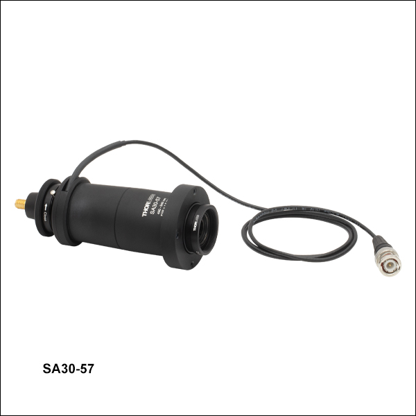 ズーム
ズーム
Click to Enlarge
SA30シリーズ干渉計のミラーの反射特性
- ニアコンフォーカルファブリペロー設計、1 MHz未満の分解能
- 高フィネス: ≥1500
- 10%~20%の共鳴透過(典型値)
- 熱的安定性に優れた高安定なインバー製共振器
- 低い走査電圧(633 nmでFSRあたり2.5 V)
- フランジはØ50.8 mm(Ø2インチ)で、当社のキネマティックマウントKS2やKC2L/Mに取り付け可能
- SMA‐BNCケーブル付属
SA30シリーズのファブリペロー干渉計のフリースペクトルレンジは1.5 GHzです。フィネスは最小で1500、分解能は1 MHz未満です。コーティングの波長範囲は6種類ご用意しております。下表をご覧ください。これらのコーティングの波長特性の詳細は「グラフ」タブをご参照ください。
UV~中赤外域(200 nm~4700 nm)におけるカスタム仕様のミラーコーティングも、ご要望に応じて承ります。下表に必要とするコーティングが無い場合には、当社までお問い合わせください。
| Item # | Wavelength Range | Free Spectral Rangea | Total Finesse | Resolution | Cavity Lengthb | Mirror Substrate | Detector |
|---|---|---|---|---|---|---|---|
| SA30-47 | 400 - 535 nm | 1.5 GHz | ≥1500 | < 1 MHz | 50 mm | UV Fused Silica | Yes |
| SA30-57 | 490 - 640 nm | ||||||
| SA30-73 | 630 - 824 nm | ||||||
| SA30-95 | 824 - 1071 nm | ||||||
| SA30-120 | 1060 - 1350 nm | ||||||
| SA30-144 | 1250 - 1625 nm | IR-Grade Fused Silica (Infrasil®) |

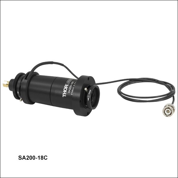 ズーム
ズーム
Click to Enlarge
SA200シリーズ干渉計のミラーの反射特性

- 共焦点ファブリペロー型
- 波長範囲:UV~中赤外域
- 熱的安定性に優れた高安定なインバー製共振器
- 低電圧で走査可能(633 nmでFSRあたり2.5 V)
- フランジ径はØ50.8 mm(Ø2インチ)で、当社のマウントKS2やKC2L/Mに取り付け可能
- SMA-BNCケーブルが付属(SA200-30Cを除く)
SA200シリーズのファブリペロー干渉計のフリースペクトルレンジは1.5 GHzです。フィネスは最小で200、分解能は7.5 MHzです。 290~4400 nmの波長域で光学コーティングを7種類ご用意しております。これにはデュアル波長コーティングの製品(SA200-2B)が含まれます。下の表と右のグラフをご参照ください。詳細は「グラフ」タブをご覧ください。UV~中赤外域(200 nm~4700 nm)におけるカスタム仕様のミラーコーティングも、ご要望に応じて承ります。下表に必要とするコーティングが無い場合には、当社までお問い合わせください。
SA200-18Cに付属するフォトダイオードディテクタは1.8~2.6 µmの波長に感度があります。この製品のミラーの反射率は2.6~2.8 µmにおいても99.0%を超えるため、ほかのディテクタと交換すればより広い波長範囲で使用可能です。その目的に適したものとして、当社ではPDA10PT-ECのご使用をお勧めしています。ファブリペロー干渉計にはレンズチューブ用カプラSM1T2を用いて取り付けることができます。
SA200-30Cは3.0~4.4 µm用にコーティングされており、ディテクタは付属しておりません。当社では2.7~5.0 µmの波長域に感度のあるHgCdTe増幅フォトディテクタPDAVJ5のご使用をお勧めしています。PDAVJ5はSM1外ネジ付き、SA200-30CはSM1内ネジ付きのため、追加のネジアダプタ無しで直接取り付けることができます。 なおPDAVJ5にはトランスインピーダンスアンプが内蔵されているため、干渉計をご使用になるときに、ディテクタの出力をコントローラSA201Bのトランスインピーダンスアンプに接続しないでください。また、SA200-30Cに入射する光パワーは、PDAVJ5内のダイオードを飽和させないために200 µW以下にしてください。
| Item # | Wavelength Range | Free Spectral Range | Total Finesse | Resolution | Cavity Lengtha | Mirror Substrate | Detector |
|---|---|---|---|---|---|---|---|
| SA200-2B | 290 - 355 nm; 520 - 545 nm | 1.5 GHz | > 200 (250 Typ.) | 7.5 MHz | 50 mm | UV Fused Silica | Yes |
| SA200-3B | 350 - 535 nm | ||||||
| SA200-5B | 535 - 820 nm | ||||||
| SA200-8B | 820 - 1275 nm | ||||||
| SA200-12B | 1275 - 2000 nm | ||||||
| SA200-18C | 1800 - 2600 nm | IR-Grade Fused Silica (Infrasil®) | |||||
| SA200-30C | 3000 - 4400 nm | Yttrium Aluminum Garnet (YAG) | No |

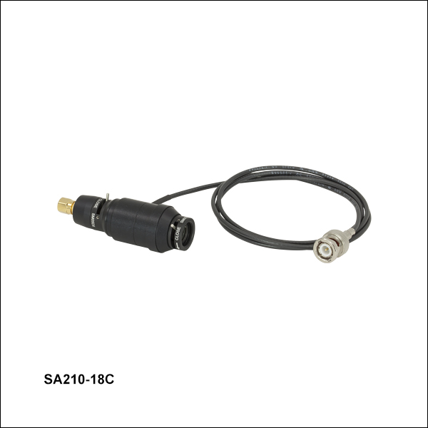 ズーム
ズーム
Click to Enlarge
SA210シリーズ干渉計のミラーの反射特性
- 共焦点ファブリペロー干渉計
- 超安定インバ製アサーマル共振器
- 低い走査電圧(633 nmでFSRあたり2.5 V)
- フランジはØ25.4 mm(Ø1インチ)で、当社のマウントKS1やKC1L/Mに取付け可能
- SMA - BNC接続ケーブルが付属
SA210シリーズファブリペロー干渉計のフリースペクトルレンジは10 GHzです。フィネスは最小で150、分解能は67 MHzとなっています。5種類の波長範囲用をご用意しています。下の表と右のグラフをご参照ください。詳細は、「グラフ」タブをご覧ください。UV~中赤外域(200 nm~4700 nm)におけるカスタム仕様のミラーコーティングも、ご要望に応じて承ります。下表に必要とするコーティングが無い場合には、当社までお問い合わせください。
注:SA210-18Cに付属するフォトダイオードディテクタは1.8~2.6 µmの波長に対応します。このデバイスのミラーの反射率は2.6~2.8 µmにおいても99.0%を超えるため、ほかのディテクタと交換するとより広い波長範囲で使用が可能となります。この場合、レンズチューブカプラSM1T2を使用してファブリペロー干渉計に取り付けが可能なディテクタPDA10PT-ECをお勧めいたします。
| Item # | Wavelength Range | Free Spectral Range | Total Finesse | Resolution | Cavity Lengtha | Mirror Substrate | Detector |
|---|---|---|---|---|---|---|---|
| SA210-3B | 350 - 535 nm | 10 GHz | > 150 (180 Typ.) | 67 MHz | 7.5 mm | UV Fused Silica | Yes |
| SA210-5B | 535 - 820 nm | ||||||
| SA210-8B | 820 - 1275 nm | ||||||
| SA210-12B | 1275 - 2000 nm | ||||||
| SA210-18C | 1800 - 2600 nm | IR-Grade Fused Silica (Infrasil®) |

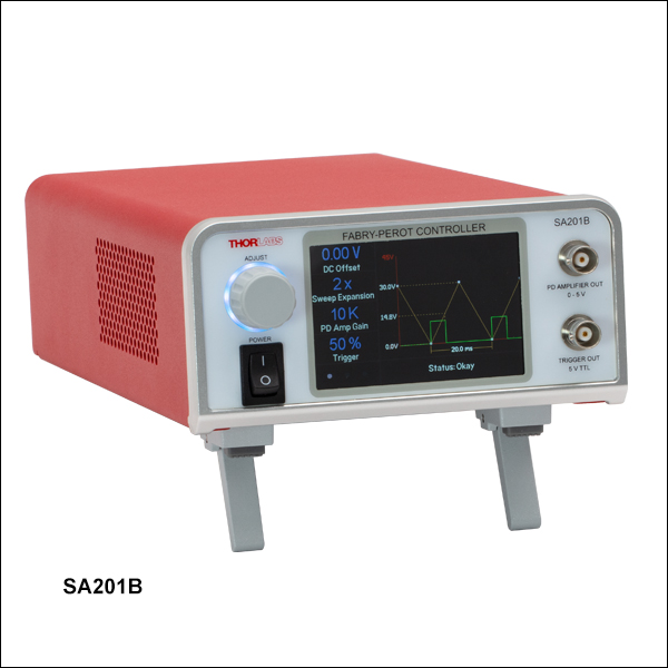 ズーム
ズーム| Ramp Specifications | |
|---|---|
| Waveform | Sawtooth or Triangle |
| Output Voltage Range | 1 - 45 V (Offset + Amplitude) |
| Monitor Output Attenuation | 10:1 (Output:Monitor) |
| Offset Adjustment Range | 0 - 15 VDC |
| Amplitude Adjustment Range | 1 - 30 V (Peak to Peak) |
| Rise Time Adjustment Range | 1X Sweep Expansion: 0.01 - 0.1 s 100X Sweep Expansion: 1 - 10 s |
| Sweep Expansion | 1X, 2X, 5X, 10X, 20X, 50X, 100X |
| Sweep Scale Error | ±0.5% |
| Output Noise | 1 mV (RMS) ~6.6 mV (Peak to Peak) |
| Trigger Voltage | 5 V TTL |
| Trigger Rise Edge | Ramp Start |
| Trigger Fall Edge | 1% to 99% User Adjustable |
| Photoamplifier Specifications | |
|---|---|
| Gain Steps (Hi-Z) | 10, 100, or 1000 kV/A |
| Output Voltage (Hi-Z) | 0 - 5 V |
| Bandwidth | 250 kHz |
| Noise (RMS) | < 0.1 mV @ 10 kV/A 0.2 mV @ 100 kV/A 1.5 mV @ 1000 kV/A |
- TTLトリガ出力
- ランプ信号開始時は、立ち上がりエッジでトリガ
- ランプ信号の途中では、タイミングを調整できる立ち下がりエッジでトリガ
- 波形の位置を調整することで、走査電圧のDCオフセットの調整が可能
- 走査時間の調整範囲:0.01~10s
- 走査電圧波形:三角波または鋸歯状波
- フォトダイオード出力信号用にトランスインピーダンスゲインアンプを内蔵
- デバイス制御用のタッチパネル式LCDディスプレイ
SA201Bは当社のファブリペロー干渉計の制御用に設計されており、安定した低ノイズのランプ電圧信号を発生させることができます。このランプ信号は2枚のキャビティーミラー間の距離を走査するために使用されます。
コントローラの前面パネルにはLCDタッチパネル、およびファブリペロー干渉計とオシロスコープを接続するための2つのメス型BNCポートが付いています。このLCDインターフェイスを使用してランプ信号の電圧や走査時間を調整できます。このLCDでは走査範囲や速度のほかに電圧オフセットも調整できるため、オシロスコープ上に表示されるスペクトルを左右にシフトさせることが可能です。コントローラの背面パネルには、同じ干渉計とオシロスコープに接続するための追加的なメス型BNCポートが3つ付いています。詳細は「接続」タブをご覧ください。
コントローラSA201Bには、キャビティの透過光をモニタするために、高精度なフォトディテクタ(PD)用増幅回路が内蔵されています。この増幅器はオシロスコープのような高インピーダンス負荷を駆動するとき、トランスインピーダンスゲインを10 kV/A、100 kV/A、または1000 kV/Aの何れかに設定できます。コントローラからのPD増幅器出力信号をオシロスコープに入力することで、入射レーザのスペクトルを表示することができます。ディテクタ回路にはブランキング回路が組み込まれており、鋸歯状波の立ち下がりエッジでフォトダイオードの応答をブロックすることができます。
ランプ波形の開始時、またはランプ波形途中の設定した位置(タイミング;中間点を含む)でトリガ信号を出力することで、オシロスコープに対して外部トリガをかけることができます。ランプ信号の途中の様々な位置(タイミング)でオシロスコープにトリガ信号を出力することができるため、スペクトルのライン形状を拡大して見ることが容易にできます。見たいスペクトルの部分を画面中央に配置し、スコープのタイムベースを拡大するだけで済みます。信号を再び中央に置くためにオフセット量の操作をしなくても、オシロスコープは対象とするポイント付近を拡大表示できます。拡大機能は校正されており、それを用いてランプ信号の走査幅を1倍、2倍、5倍、10倍、20倍、50倍、100倍に拡大できるため、非常に広範囲の走査が可能です。 このコントローラは、当社の走査型ファブリペロー干渉計用の制御ソフトウェアを使用して、PCでリモート操作も行えます。ソフトウェア開発キット(SDK)もご用意していますので、このコントローラをほかのシステムに組込むことも可能です。システム要件やダウンロードについては「SA201B用ソフトウェア」タブをご覧ください。
尚、SA201Bには国内対応の電源ケーブルが付属しています。