 Products Home
ゼロオーダー1/2波長板、石英製、マウント付き
- Compound Zero-Order Operation Achieved by Using Two Multi-Order Plates
- AR Coating for Design Wavelengths from 266 nm to 2020 nm
- Lower Dependence on Temperature and Wavelength than Multi-Order
Wave Plates
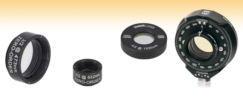
WPH10M-473
473 nm Wave Plate in
SM1-Threaded Lens Tube
WPHSM05-532
532 nm Wave Plate in
SM05-Threaded Lens Tube
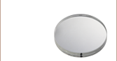
WPH05M-1030
1030 nm Wave Plate in Unthreaded Ø1" Mount
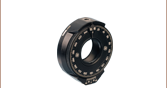
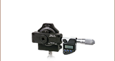
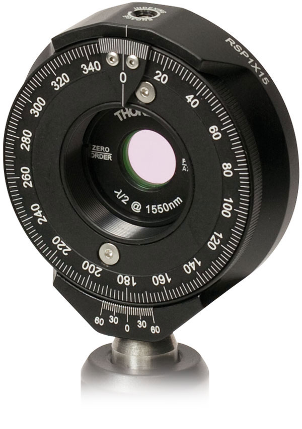
Ø1" Half-Wave Plate
Mounted in RSP1X15
Indexing Rotation Mount


Please Wait
| Common Specifications | |
|---|---|
| Material | Crystalline Quartz |
| Retardance Accuracy (Typical) | < λ/300 |
| Beam Deviation | < 10 arcsec |
| Surface Quality | 20-10 Scratch-Dig |
| Reflectance @ Design Wavelength (per Surface) | < 0.25% |
| 各種資料のご案内 | |
|---|---|
| 仕様やグラフ、図面等の情報は、仕様表内のInfo欄の青いアイコンからご確認可能です。 | |
特長
- エアスペース設計による高い損傷閾値
- 波長範囲266 nm~2020 nm
- 両面にARコーティング付き
- 波長板サイズØ12.7 mm(Ø1/2インチ)とØ25.4 mm(Ø1インチ)から選択可
- 特注や大量発注、組み込み用途(OEM用途)にも対応いたします(当社までご連絡ください)。
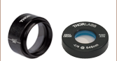
当社のゼロオーダ波長板は、光路長差が1/2波長となるよう2枚のマルチオーダ結晶石英波長板を組み合わせて作られています。1枚の波長板のファスト軸をもう1枚のスロー軸に合わせることによって、2枚の波長板の位相差による正確なリターダンスを持つ複合リターダとなっています。複合ゼロオーダ波長板は、マルチオーダ波長板よりも温度や波長への依存性はかなり低くなっています。製品は、Ø25.4 mm(Ø1インチ)のネジ切りなし筐体に取付けたØ12.7 mm(Ø1/2インチ)波長板、SM05ネジ付きレンズチューブに取付けたØ12.7 mm(Ø1/2インチ)波長板、SM1ネジ付きレンズチューブに取付けたØ25.4 mm(Ø1インチ)波長板をご用意しております(詳細については下記をご覧ください)。
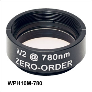
これらのゼロオーダ波長板は、2枚のマルチオーダ波長板の間にエッチング加工を施した ステンレス製スペーサーリングを配置して、それら3つを接着剤で固定することによって作られています(接着剤は波長板の開口の外側だけに付いています)。 また、波長板はアルマイト加工のアルミ製筐体に実装されています。筐体には、波長板のファスト軸の方向を示す線、ゼロオーダ1/2波長板であることを示す表示、波長板の対象波長が刻印されています。
 Click to Enlarge
当社ではARコーティング無しまたは異なるARコーティング付き、あるいは下記以外の設計波長のカスタム波長板も製造可能です。詳細は当社までお問い合わせください。
当社では、大きい入射角(AOI)でも安定的な性能を発揮するポリマーゼロオーダ1/4波長板や1/2波長板もご用意しております。
取付けについて
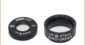
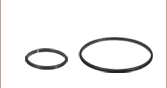
SM05とSM1ネジ付き筐体に入った波長板は、それぞれSM05ネジおよびSM1ネジの付いた回転マウントに直接取付けられます。Ø25.4 mmマウント付きØ12.7 mm(Ø1/2インチ)波長板は、回転リングSM1RRを使用してSM1内ネジ付き部品に固定できます。
波長板は、マウントから簡単に取外して、カスタム仕様や組み込み用途(OEM用途)にもご使用いただけます。取り外すにはスパナレンチを使用して固定リングを外してください(Ø12.7 mm(Ø1/2インチ)モデルにはSM05用、Ø25.4 mm(Ø1インチ)モデルにはSM1用のスパナレンチをご使用ください)。マウント無しの波長板には小さい切り欠きがあり、そのフラットな部分はファスト軸に平行になっています(右図参照)。波長板の使用や選択に関する詳細は「波長板セレクションガイド」タブをご覧いただくか、当社までお問い合わせください。
波長板の動作原理
波長板は、2本の直交する軸方向の偏光に対して異なる屈折率を有する複屈折性材料から造られています。この複屈折性によって、波長板のファスト軸方向の偏光とスロー軸方向の偏光に速度の差が生じます。波長板のファスト軸方向の偏光に対する屈折率は小さいため、その方向に偏光した光は速く進みます。反対にスロー軸方向の偏光に対する屈折率は大きいので、その方向に偏光した光の速度は遅くなります。光が波長板を通過するとき、この速度の差によって2つの直交する偏光成分の間に位相差が生じます。実際の位相差は材料の特性、波長板の厚さ、および入射光の波長に依存し、次の式で表わされます。
![]()
ここで、n1はスロー軸方向の偏光に対する屈折率、n2はそれに直交するファスト軸方向の偏光に対する屈折率、dは波長板の厚さ、λは入射光の波長です。
波長板の使用
波長板には一般的にリターダンスが1/4波長と1/2波長のものがあり、それぞれ波長の1/4または1/2の位相シフトが生じることを意味しています。
1/2波長板
上述のように、波長板にはファスト軸とスロー軸があります。各軸の屈折率が異なるので、それぞれの速度も異なります。1/2波長板に直線偏光が入射したとき、その偏光方向が波長板のどちらの主軸にも一致しない場合は、出射光は入射光の偏光方向を回転した直線偏光になります(右図参照)。円偏光が入射したときは、入射光の偏光が時計回り(反時計回り)であれば、出射光は反時計回り(時計回り)の円偏光になります。
1/2波長板は、偏光状態を回転させる目的で使用されることが一般的です。回転式マウントに1/2波長板を取り付けると、下図のように連続可変偏光ローテータとして使用できます。さらに偏光ビームスプリッタと一緒に使用することにより、1/2波長板は、分岐比が調整可能なビームスプリッタとして機能します。
出射偏光と入射偏光のなす角度は、入射偏光軸と波長板の軸がなす形成する角度の2倍となります(右下の図参照)。入射光の偏光が、波長板のいずれかの光軸と一致するとき、偏光状態の向きは変化しません。
1/4波長板
1/4波長板はファスト軸方向とスロー軸方向の偏光に生じる位相差が1/4波長 (λ/4)になるように設計されています。波長板のファスト軸またはスロー軸に対して偏光方向を45°に設定した直線偏光を入射した場合、出射光は円偏光に変換されます(右図参照)。直線偏光を45°以外の角度に設定した場合は、出射光は楕円偏光に変換されます。反対に、円偏光を1/4 波長板に入射した場合、出射光は直線偏光になります。1/4波長板は光アイソレータ、光ポンプ、EO変調器などに使用されています。
Click to Enlarge
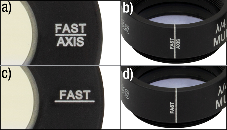
図1: (a、b):2018年10月から新しい工程で組み立てられた製品の刻印。(c、d):旧工程の製品の刻印
ファスト軸ならびにスロー軸の特定
当社は2018年10月に、波長板のファスト軸とスロー軸の決定に関するIEEE/SPIEによる取り決め(IEEE/SPIE convention: Polarization Handedness Tutorialを参照)に適合させるために、組立工程と関連製品の刻印を新しくしました。この取り決めにより、新しい工程で組み立てられた波長板のファスト軸には、右の図1のように「FAST AXIS」の刻印があります。波長板の主軸の位置とリターダンスを決定するのは比較的容易ですが、ファスト軸とスロー軸の識別方法は遥かに複雑です。
多くの用途においては、ファスト軸とスロー軸を識別することよりも、リターダンスの値を知ることの方が重要です。しかし、ファスト軸かスロー軸かによって1/4波長板から出射する円偏光の回転方向(左/右)が決まるため、原子物理学や固体物理学における分光分野では重要になる場合があります。表示の精度をより確実にするために、当社では下記のように製造工程に複数の試験を組み込みました。
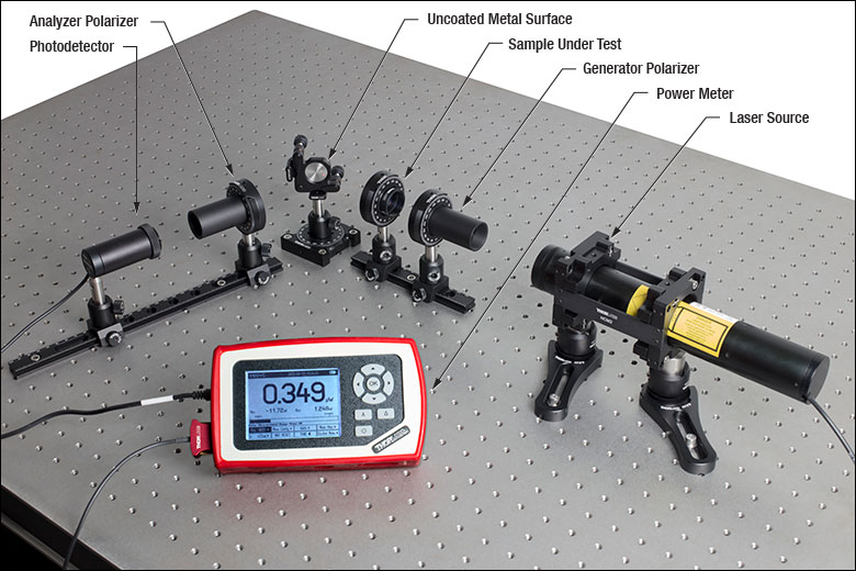
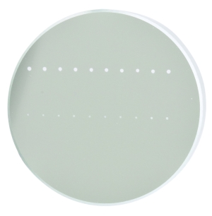
試験セットアップ1: n > 1の無コーティング金属面による反射
このセットアップはPetre Logofatu1の方法に基づいており、またGalgano and Henriques2にもその優れた要約が記載されています。この方法では、まず光源からの光を偏光ジェネレータに通しますが、これは水平方向に対して45°の方向を向いた直線偏光子です。その後、光は試験品(SUT)である波長板を通り、無コーティングの金属表面(n > 1の金属であれば十分)で反射され、アナライザ(ジェネレータに対して90°に配置された2つめの直線偏光子)を通ります。最後に、光はパワーセンサで測定されます。
右の図2に示している当社のセットアップでは、光源としてHeNeレーザ、偏光ジェネレータとアナライザとして2つのグラントムソン偏光子GTH10M-A、カスタム仕様の無コーティングステンレススチール反射面、パワーセンサS120C、およびパワーメーターコンソールPM100Dを使用しています。図2の下にはカスタム仕様の金属面とSUT以外に使用した部品のリストがご覧いただけます。
Logofatuに述べられているように、下の式のパワー反射係数Rは、フレネルの式から導かれ、これはSUTのファスト軸あるいはスロー軸が水平方向にあるか否かによって金属からの反射量が大きく異なることを示しています。
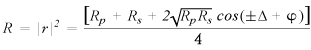
ここでRp とRs はRのp偏光成分とs偏光成分、ΔはSUTのリターダンス、φは金属表面のp偏光とs偏光の反射係数の位相差です。これにより、どちらの主軸が水平方向に置かれたときに大きな反射を期待できるかが分かり、予測値と実験値の比較ができます。入射角を大きくするとs偏光とp偏光の反射係数の差は大きくなります。このことは反射量の測定値の大きさと相関するため、ファスト軸とスロー軸の判別がより容易になります。両論文と同じように、試験は様々な入射角で実施しています。その結果を理論曲線にあてはめています。
上記のRの式が、Logofatuの式とは異なるのは式に誤りを見つけたからです。こちらの反射係数の導出(PDF)で当社独自で行った導出を述べています。
Click to Enlarge
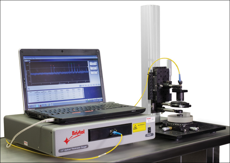
図 3:低コヒーレンス干渉計を用いた試験のセットアップ
試験セットアップ2: 低コヒーレンス干渉計
こちらの試験のセットアップでは、低コヒーレンス干渉計を使用して、SUTを回転させながら光路長(OPL)を測定します。最長の光路長がスロー軸、最短の光路長がファスト軸に対応します。この方法では、干渉計に改造を加え、結晶軸に沿う方向と垂直な方向の群屈折率(ngSUT)を計算できるように参照用ウィンドウと背面に反射鏡を追加して、さらに検証ができるようにしています。それらの値は既知の値と比較することができるため、この試験の信頼性を確かなものにすることができます。
右の図3に示す当社のセットアップでは、Bristol 157シリーズの光学的厚さゲージを改造して使用しています。下の図4でご覧いただけるように、低コヒーレンス干渉計の大部分は光学的厚さゲージaのシャーシ内に納められています。測定アームは当社の部品を用いて改造を行い、ファイバからの出力光は低NAの対物レンズにアライメントされており、直線偏光子LPNIR100を通ったのち、参照ウィンドウWG11010で部分的に反射されるようになっています。またこれらの部品はすべて34 mmレールに取り付けられています。その後、光はSUTと背面の反射鏡で反射され、干渉用の信号光は光学的厚さゲージに戻ります。
追加された参照面と測定から得られたそれらの物理的厚さは、測定結果の有効性を再確認するのに使用されます。これは、ファスト軸とスロー軸両方の群屈折率を求める簡単な計算によって行われます。図5は、このセットアップによって生成される出力信号を定性的に示しています。Peak 1と2は参照ウィンドウによって、Peak 3と4はSUT(波長板)によって、Peak 5は参照用の反射面によってそれぞれ生成されます。厚さのデータはPeak-to-Peakの信号からソフトウェアによって算出され、表に出力されます。波長板を挿入する前にPeak 2~Peak 5の距離を測ることにより、全体の物理的な距離Tair0が得られますb。波長板挿入後は、Peak 2~3の距離Tair1と、Peak 4~5の距離Tair2を測ります。この情報を利用し、Tair0からTair1とTair2を差し引くことにより、波長板の厚さ TSUT を簡単に求めることができます。Peak 3~Peak 4の距離を測定することにより、OPLSUTが分かります。OPLSUTをTSUTで割ると、SUTの群屈折率ngSUTが得られます。この群屈折率を、文献にある石英3あるいはMgF24 の結晶軸方向およびその垂直方向の群屈折率と比較すると、結果は一致します。
Click to Enlarge
図 4: 低コヒーレンス干渉計の図解例。測定アームに記載されている反射の番号は、図5のPeakの番号に対応しています。
Click to Enlarge
図5: 光学的厚さゲージからの出射信号
| Damage Threshold Specifications | |
|---|---|
| Coating Designation (Item # Suffix) | Damage Threshold |
| -266 | 10 J/cm2 (266 nm, 10 ns, 10 Hz, Ø0.228 mm) |
| -355 | 10 J/cm2 (355 nm, 10 ns, 10 Hz, Ø0.179 mm) |
| -532 | 10 J/cm2 (532 nm, 10 ns, 10 Hz, Ø0.242 mm) |
| -808 | 0.448 J/cm2 (797 nm, 180 fs, 1 kHz, Ø0.178 mm) 10 J/cm2 (810 nm, 10 ns, 10 Hz, Ø0.055 mm) |
| -1064 | 10 J/cm2 (1064 nm, 10 ns, 10 Hz, Ø0.433 mm) |
| -1550 | 20 J/cm2 (1542 nm, 10 ns, 10 Hz, Ø0.105 mm) |
| -2020 | 10 J/cm2 (2050 nm, 10 ns, 10 Hz, Ø0.186 mm) |
当社の波長板の損傷閾値データ
右の仕様は当社の波長板の測定値です。損傷閾値の仕様は、波長板のサイズにかかわらず中心波長が同じすべての波長板で同じです。
レーザによる損傷閾値について
このチュートリアルでは、レーザ損傷閾値がどのように測定され、使用する用途に適切な光学素子の決定にその値をどのようにご利用いただけるかを総括しています。お客様のアプリケーションにおいて、光学素子を選択する際、光学素子のレーザによる損傷閾値(Laser Induced Damage Threshold :LIDT)を知ることが重要です。光学素子のLIDTはお客様が使用するレーザの種類に大きく依存します。連続(CW)レーザは、通常、吸収(コーティングまたは基板における)によって発生する熱によって損傷を引き起こします。一方、パルスレーザは熱的損傷が起こる前に、光学素子の格子構造から電子が引き剥がされることによって損傷を受けます。ここで示すガイドラインは、室温で新品の光学素子を前提としています(つまり、スクラッチ&ディグ仕様内、表面の汚染がないなど)。光学素子の表面に塵などの粒子が付くと、低い閾値で損傷を受ける可能性があります。そのため、光学素子の表面をきれいで埃のない状態に保つことをお勧めします。光学素子のクリーニングについては「光学素子クリーニングチュートリアル」をご参照ください。
テスト方法
当社のLIDTテストは、ISO/DIS 11254およびISO 21254に準拠しています。
初めに、低パワー/エネルギのビームを光学素子に入射します。その光学素子の10ヶ所に1回ずつ、設定した時間(CW)またはパルス数(決められたprf)、レーザを照射します。レーザを照射した後、倍率約100倍の顕微鏡を用いた検査で確認し、すべての確認できる損傷を調べます。特定のパワー/エネルギで損傷のあった場所の数を記録します。次に、そのパワー/エネルギを増やすか減らすかして、光学素子にさらに10ヶ所レーザを照射します。このプロセスを損傷が観測されるまで繰返します。損傷閾値は、光学素子が損傷に耐える、損傷が起こらない最大のパワー/エネルギになります。1つのミラーBB1-E02の試験結果は以下のようなヒストグラムになります。
上の写真はアルミニウムをコーティングしたミラーでLIDTテストを終えたものです。このテストは、損傷を受ける前のレーザのエネルギは0.43 J/cm2 (1064 nm、10 ns pulse、 10 Hz、Ø1.000 mm)でした。
| Example Test Data | |||
|---|---|---|---|
| Fluence | # of Tested Locations | Locations with Damage | Locations Without Damage |
| 1.50 J/cm2 | 10 | 0 | 10 |
| 1.75 J/cm2 | 10 | 0 | 10 |
| 2.00 J/cm2 | 10 | 0 | 10 |
| 2.25 J/cm2 | 10 | 1 | 9 |
| 3.00 J/cm2 | 10 | 1 | 9 |
| 5.00 J/cm2 | 10 | 9 | 1 |
試験結果によれば、ミラーの損傷閾値は 2.00 J/cm2 (532 nm、10 ns pulse、10 Hz、 Ø0.803 mm)でした。尚、汚れや汚染によって光学素子の損傷閾値は大幅に低減されるため、こちらの試験はクリーンな光学素子で行っています。また、特定のロットのコーティングに対してのみ試験を行った結果ではありますが、当社の損傷閾値の仕様は様々な因子を考慮して、実測した値よりも低めに設定されており、全てのコーティングロットに対して適用されています。
CWレーザと長パルスレーザ
光学素子がCWレーザによって損傷を受けるのは、通常バルク材料がレーザのエネルギを吸収することによって引き起こされる溶解、あるいはAR(反射防止)コーティングのダメージによるものです[1]。1 µsを超える長いパルスレーザについてLIDTを論じる時は、CWレーザと同様に扱うことができます。
パルス長が1 nsと1 µs の間のときは、損傷は吸収、もしくは絶縁破壊のどちらかで発生していると考えることができます(CWとパルスのLIDT両方を調べなければなりません)。吸収は光学素子の固有特性によるものか、表面の不均一性によるものかのどちらかによって起こります。従って、LIDTは製造元の仕様以上の表面の質を有する光学素子にのみ有効です。多くの光学素子は、ハイパワーCWレーザで扱うことができる一方、アクロマティック複レンズのような接合レンズやNDフィルタのような高吸収光学素子は低いCWレーザ損傷閾値になる傾向にあります。このような低い損傷閾値は接着剤や金属コーティングにおける吸収や散乱によるものです。
線形パワー密度におけるLIDTに対するパルス長とスポットサイズ。長パルス~CWでは線形パワー密度はスポットサイズにかかわらず一定です。 このグラフの出典は[1]です。

繰返し周波数(prf)の高いパルスレーザは、光学素子に熱的損傷も引き起こします。この場合は吸収や熱拡散率のような因子が深く関係しており、残念ながらprfの高いレーザが熱的影響によって光学素子に損傷を引き起こす場合の信頼性のあるLIDTを求める方法は確立されておりません。prfの大きいビームでは、平均出力およびピークパワーの両方を等しいCW出力と比較する必要があります。また、非常に透過率の高い材料では、prfが上昇してもLIDTの減少は皆無かそれに近くなります。
ある光学素子の固有のCWレーザの損傷閾値を使う場合には、以下のことを知る必要があります。
- レーザの波長
- ビーム径(1/e2)
- ビームのおおよその強度プロファイル(ガウシアン型など)
- レーザのパワー密度(トータルパワーをビームの強度が1/e2の範囲の面積で割ったもの)
ビームのパワー密度はW/cmの単位で計算します。この条件下では、出力密度はスポットサイズとは無関係になります。つまり、スポットサイズの変化に合わせてLIDTを計算し直す必要がありません(右グラフ参照)。平均線形パワー密度は、下の計算式で算出できます。
ここでは、ビーム強度プロファイルは一定であると仮定しています。次に、ビームがホットスポット、または他の不均一な強度プロファイルの場合を考慮して、おおよその最大パワー密度を計算する必要があります。ご参考までに、ガウシアンビームのときはビームの強度が1/e2の2倍のパワー密度を有します(右下図参照)。
次に、光学素子のLIDTの仕様の最大パワー密度を比較しましょう。損傷閾値の測定波長が光学素子に使用する波長と異なっている場合には、その損傷閾値は適宜補正が必要です。おおよその目安として参考にできるのは、損傷閾値は波長に対して比例関係であるということです。短い波長で使う場合、損傷閾値は低下します(つまり、1310 nmで10 W/cmのLIDTならば、655 nmでは5 W/cmと見積もります)。
この目安は一般的な傾向ですが、LIDTと波長の関係を定量的に示すものではありません。例えば、CW用途では、損傷はコーティングや基板の吸収によってより大きく変化し、必ずしも一般的な傾向通りとはなりません。上記の傾向はLIDT値の目安として参考にしていただけますが、LIDTの仕様波長と異なる場合には当社までお問い合わせください。パワー密度が光学素子の補正済みLIDTよりも小さい場合、この光学素子は目的の用途にご使用いただけます。
当社のウェブ上の損傷閾値の仕様と我々が行った実際の実験の値の間にはある程度の差があります。これはロット間の違いによって発生する誤差を許容するためです。ご要求に応じて、当社は個別の情報やテスト結果の証明書を発行することもできます。損傷解析は、類似した光学素子を用いて行います(お客様の光学素子には損傷は与えません)。試験の費用や所要時間などの詳細は、当社までお問い合わせください。
パルスレーザ
先に述べたように、通常、パルスレーザはCWレーザとは異なるタイプの損傷を光学素子に引き起こします。パルスレーザは損傷を与えるほど光学素子を加熱しませんが、光学素子から電子をひきはがします。残念ながら、お客様のレーザに対して光学素子のLIDTの仕様を照らし合わせることは非常に困難です。パルスレーザのパルス幅に起因する光学素子の損傷には、複数の形態があります。以下の表中のハイライトされた列は当社の仕様のLIDT値が当てはまるパルス幅に対する概要です。
パルス幅が10-9 sより短いパルスについては、当社の仕様のLIDT値と比較することは困難です。この超短パルスでは、多光子アバランシェ電離などのさまざまなメカニクスが損傷機構の主流になります[2]。対照的に、パルス幅が10-7 sと10-4 sの間のパルスは絶縁破壊、または熱的影響により光学素子の損傷を引き起こすと考えられます。これは、光学素子がお客様の用途に適しているかどうかを決定するために、レーザービームに対してCWとパルス両方による損傷閾値を参照しなくてはならないということです。
| Pulse Duration | t < 10-9 s | 10-9 < t < 10-7 s | 10-7 < t < 10-4 s | t > 10-4 s |
|---|---|---|---|---|
| Damage Mechanism | Avalanche Ionization | Dielectric Breakdown | Dielectric Breakdown or Thermal | Thermal |
| Relevant Damage Specification | No Comparison (See Above) | Pulsed | Pulsed and CW | CW |
お客様のパルスレーザに対してLIDTを比較する際は、以下のことを確認いただくことが重要です。
エネルギ密度におけるLIDTに対するパルス長&スポットサイズ。短パルスでは、エネルギ密度はスポットサイズにかかわらず一定です。このグラフの出典は[1]です。
- レーザの波長
- ビームのエネルギ密度(トータルエネルギをビームの強度が1/e2の範囲の面積で割ったもの)
- レーザのパルス幅
- パルスの繰返周波数(prf)
- 実際に使用するビーム径(1/e2 )
- ビームのおおよその強度プロファイル(ガウシアン型など)
ビームのエネルギ密度はJ/cm2の単位で計算します。右のグラフは、短パルス光源には、エネルギ密度が適した測定量であることを示しています。この条件下では、エネルギ密度はスポットサイズとは無関係になります。つまり、スポットサイズの変化に合わせてLIDTを計算し直す必要がありません。ここでは、ビーム強度プロファイルは一定であると仮定しています。ここで、ビームがホットスポット、または他の不均一な強度プロファイルの場合を考慮して、おおよその最大パワー密度を計算する必要があります。ご参考までに、ガウシアンビームのときは一般にビームの強度が1/e2のときの2倍のパワー密度を有します。
次に、光学素子のLIDTの仕様と最大エネルギ密度を比較しましょう。損傷閾値の測定波長が光学素子に使用する波長と異なっている場合には、その損傷閾値は適宜補正が必要です[3]。経験則から、損傷閾値は波長に対して以下のような平方根の関係であるということです。短い波長で使う場合、損傷閾値は低下します(例えば、1064 nmで 1 J/cm2のLIDTならば、532 nmでは0.7 J/cm2と計算されます)。
波長を補正したエネルギ密度を得ました。これを以下のステップで使用します。
ビーム径は損傷閾値を比較する時にも重要です。LIDTがJ/cm2の単位で表される場合、スポットサイズとは無関係になりますが、ビームサイズが大きい場合、LIDTの不一致を引き起こす原因でもある不具合が、より明らかになる傾向があります[4]。ここで示されているデータでは、LIDTの測定には<1 mmのビーム径が用いられています。ビーム径が5 mmよりも大きい場合、前述のようにビームのサイズが大きいほど不具合の影響が大きくなるため、LIDT (J/cm2)はビーム径とは無関係にはなりません。
次に、パルス幅について補正します。パルス幅が長くなるほど、より大きなエネルギに光学素子は耐えることができます。パルス幅が1~100 nsの場合の近似式は以下のようになります。
お客様のレーザのパルス幅をもとに、光学素子の補正されたLIDTを計算するのにこの計算式を使います。お客様の最大エネルギ密度が、この補正したエネルギ密度よりも小さい場合、その光学素子はお客様の用途でご使用いただけます。ご注意いただきたい点は、10-9 s と10-7 sの間のパルスにのみこの計算が使えることです。パルス幅が10-7 sと10-4 sの間の場合には、CWのLIDTも調べなければなりません。
当社のウェブ上の損傷閾値の仕様と我々が行った実際の実験の値の間にはある程度の差があります。これはロット間の違いによって発生する誤差を許容するためです。ご要求に応じて、当社では個別のテスト情報やテスト結果の証明書を発行することも可能です。詳細は、当社までお問い合わせください。
[1] R. M. Wood, Optics and Laser Tech. 29, 517 (1998).
[2] Roger M. Wood, Laser-Induced Damage of Optical Materials (Institute of Physics Publishing, Philadelphia, PA, 2003).
[3] C. W. Carr et al., Phys. Rev. Lett. 91, 127402 (2003).
[4] N. Bloembergen, Appl. Opt. 12, 661 (1973).

レーザーシステムが光学素子に損傷を引き起こすかどうか判断するプロセスを説明するために、レーザによって引き起こされる損傷閾値(LIDT)の計算例をいくつかご紹介します。同様の計算を実行したい場合には、右のボタンをクリックしてください。計算ができるスプレッドシートをダウンロードいただけます。ご使用の際には光学素子のLIDTの値と、レーザーシステムの関連パラメータを緑の枠内に入力してください。スプレッドシートでCWならびにパルスの線形パワー密度、ならびにパルスのエネルギ密度を計算できます。これらの値はスケーリング則に基づいて、光学素子のLIDTの調整スケール値を計算するのに用いられます。計算式はガウシアンビームのプロファイルを想定しているため、ほかのビーム形状(均一ビームなど)には補正係数を導入する必要があります。 LIDTのスケーリング則は経験則に基づいていますので、確度は保証されません。なお、光学素子やコーティングに吸収があると、スペクトル領域によってLIDTが著しく低くなる場合があります。LIDTはパルス幅が1ナノ秒(ns)未満の超短パルスには有効ではありません。
Figure 71A ガウシアンビームの最大強度は均一ビームの約2倍です。
CWレーザの例
波長1319 nm、ビーム径(1/e2)10 mm、パワー0.5 Wのガウシアンビームを生成するCWレーザーシステム想定します。このビームの平均線形パワー密度は、全パワーをビーム径で単純に割ると0.5 W/cmとなります。
しかし、ガウシアンビームの最大パワー密度は均一ビームの約2倍です(Figure 71A参照)。従って、システムのより正確な最大線形パワー密度は1 W/cmとなります。
アクロマティック複レンズAC127-030-CのCW LIDTは、1550 nmでテストされて350 W/cmとされています。CWの損傷閾値は通常レーザ光源の波長に直接スケーリングするため、LIDTの調整値は以下のように求められます。
LIDTの調整値は350 W/cm x (1319 nm / 1550 nm) = 298 W/cmと得られ、計算したレーザーシステムのパワー密度よりも大幅に高いため、この複レンズをこの用途に使用しても安全です。
ナノ秒パルスレーザの例:パルス幅が異なる場合のスケーリング
出力が繰返し周波数10 Hz、波長355 nm、エネルギ1 J、パルス幅2 ns、ビーム径(1/e2)1.9 cmのガウシアンビームであるNd:YAGパルスレーザーシステムを想定します。各パルスの平均エネルギ密度は、パルスエネルギをビームの断面積で割って求めます。
上で説明したように、ガウシアンビームの最大エネルギ密度は平均エネルギ密度の約2倍です。よって、このビームの最大エネルギ密度は約0.7 J/cm2です。
このビームのエネルギ密度を、広帯域誘電体ミラーBB1-E01のLIDT 1 J/cm2、そしてNd:YAGレーザーラインミラーNB1-K08のLIDT 3.5 J/cm2と比較します。LIDTの値は両方とも、波長355 nm、パルス幅10 ns、繰返し周波数10 Hzのレーザで計測しました。従って、より短いパルス幅に対する調整を行う必要があります。 1つ前のタブで説明したようにナノ秒パルスシステムのLIDTは、パルス幅の平方根にスケーリングします:
この調整係数により広帯域誘電体ミラーBB1-E01のLIDTは0.45 J/cm2に、Nd:YAGレーザーラインミラーのLIDTは1.6 J/cm2になり、これらをビームの最大エネルギ密度0.7 J/cm2と比較します。広帯域ミラーはレーザによって損傷を受ける可能性があり、より特化されたレーザーラインミラーがこのシステムには適していることが分かります。
ナノ秒パルスレーザの例:波長が異なる場合のスケーリング
波長1064 nm、繰返し周波数2.5 Hz、パルスエネルギ100 mJ、パルス幅10 ns、ビーム径(1/e2)16 mmのレーザ光を、NDフィルタで減衰させるようなパルスレーザーシステムを想定します。これらの数値からガウシアン出力における最大エネルギ密度は0.1 J/cm2になります。Ø25 mm、OD 1.0の反射型NDフィルタ NDUV10Aの損傷閾値は355 nm、10 nsのパルスにおいて0.05 J/cm2で、同様の吸収型フィルタ NE10Aの損傷閾値は532 nm、10 nsのパルスにおいて10 J/cm2です。1つ前のタブで説明したように光学素子のLIDTは、ナノ秒パルス領域では波長の平方根にスケーリングします。
スケーリングによりLIDTの調整値は反射型フィルタでは0.08 J/cm2、吸収型フィルタでは14 J/cm2となります。このケースでは吸収型フィルタが光学損傷を防ぐには適した選択肢となります。
マイクロ秒パルスレーザの例
パルス幅1 µs、パルスエネルギ150 µJ、繰返し周波数50 kHzで、結果的にデューティーサイクルが5%になるレーザーシステムについて考えてみます。このシステムはCWとパルスレーザの間の領域にあり、どちらのメカニズムでも光学素子に損傷を招く可能性があります。レーザーシステムの安全な動作のためにはCWとパルス両方のLIDTをレーザーシステムの特性と比較する必要があります。
この比較的長いパルス幅のレーザが、波長980 nm、ビーム径(1/e2)12.7 mmのガウシアンビームであった場合、線形パワー密度は5.9 W/cm、1パルスのエネルギ密度は1.2 x 10-4 J/cm2となります。これをポリマーゼロオーダ1/4波長板WPQ10E-980のLIDTと比較してみます。CW放射に対するLIDTは810 nmで5 W/cm、10 nsパルスのLIDTは810 nmで5 J/cm2です。前述同様、光学素子のCW LIDTはレーザ波長と線形にスケーリングするので、CWの調整値は980 nmで6 W/cmとなります。一方でパルスのLIDTはレーザ波長の平方根とパルス幅の平方根にスケーリングしますので、1 µsパルスの980 nmでの調整値は55 J/cm2です。光学素子のパルスのLIDTはパルスレーザのエネルギ密度よりはるかに大きいので、個々のパルスが波長板を損傷することはありません。しかしレーザの平均線形パワー密度が大きいため、高出力CWビームのように光学素子に熱的損傷を引き起こす可能性があります。
| Posted Comments: | |
Suwan Kang
(posted 2025-03-06 13:15:55.733) Dear Thorlabs Team,
I hope this finds you well. I am Suwan Kang and a student at KAIST Physics in Korea.
We are currently interested learning more about the Half wave plate products particularly the 'WPH10M-850'. I would appreciate if if you could provide the followings specifications:
- CW LIDT. Also I want to ask if there is a method to calculate the CW LIDT from the given Pulsed LIDT.
Your prompt response would be highly valuable. Looking forward to hearing you soon.
Best regards.
Suwan EGies
(posted 2025-03-11 04:15:03.0) Thank you for contacting Thorlabs. Since CW and pulsed lasers typically induce different types of optical damage, there is not a super good way to calculate CW LIDT based on pulsed LIDT. While we do not have an officially tested CW damage threshold for the WPH10M-850, we can check if we expect the WPH10M-850 to survive your specific laser parameters. I have reached out to you directly regarding your particular application. user
(posted 2024-10-17 20:27:44.38) Hello, I want to know the laser damage thresholds of the WPHSM05-1550 and WPHSM05-780. Is it safe if i use a 1560 nm laser with ~ 5 W and 780 nm with ~ 10 W? blarowe
(posted 2024-10-17 11:14:31.0) Thank you for contacting Thorlabs. While we don't have any explicit damage threshold data available for these waveplates, we would expect something on the order of kWs/cm. I have reached out to you to discuss your specific application. Isaline Duperon
(posted 2024-06-10 12:13:39.507) Hello,
How can I clean a fingerprint on a waveplate ? If I rub with a cleaning tissue will I scracth the surface ? (and so remove part of the coating or change the birefringent medium length). Can I use acetone or methanol ? Will it destroy the coating ?
Thanks cdolbashian
(posted 2024-06-28 11:34:45.0) Thank you for reaching out to us with this inquiry. This should be cleaned following normal optics cleaning methods with lint-free lens wipes. Ideally you would use Isopropyl alcohol or Ethanol to clean the fingerprint off. I would not necessarily “rub” it, but rather gently do unidirectional swabs following our optics cleaning tutorial: https://www.thorlabs.com/newgrouppage9.cfm?objectgroup_id=9025 Haehyuck Kwon
(posted 2023-05-23 11:16:50.693) Dear manager,
I am Haehyuck Kwon, MSc at Chosun University in South Korea. I already purchased this WPHSM05-588 product and i want to get data of optical properties (extra ordinary, ordinary refractive index) for my research.
1. Can i get data about refractive index(ne, no)?
2. And is this data the same as the HWP and QWP products (Quartz) of all reference wavelengths?
Sinceley, cdolbashian
(posted 2023-06-12 10:52:10.0) Thank you for reaching out to us with this inquiry. I have reached out to you directly with this information. Steffen Schmidt-Eberle
(posted 2023-02-28 08:54:25.603) Is it possibly to customize the lambda/2 waveplates to a wavelength of 323 nm?
I am aware that tilting a 308 nm waveplate a bit would do the job, but as this is for a customer project I would prefer a "proper" solution. jgreschler
(posted 2023-03-02 02:25:33.0) Thank you for reaching out to Thorlabs. Custom wavelength configurations can be requested by contacting techsupport@thorlabs.com. I have reached out to you directly to discuss a quote. Gunpyo Kim
(posted 2022-11-23 11:35:17.547) 1. Can it be made to order with 25 x 25 mm square substrates?
2. How much coating area do you guarantee for circular and square substrates? jgreschler
(posted 2022-11-28 02:28:59.0) Thank you for reaching out to Thorlabs. Custom item configurations can be requested by emailing techsupport@thorlabs.com. While we can do custom sizes and shapes for these, a 25x25mm square would need to be unmounted. The entire clear aperture is AR coated. Lee XINYI
(posted 2022-09-06 15:55:12.77) Can you provide unmounted waveplate? cdolbashian
(posted 2022-09-16 10:44:41.0) Thank you for reaching out to us with this inquiry! While we can do this as a custom, we do mention above in the overview that the customer does indeed have the option of removing the housing with a spanner wrench. Koray Kesim
(posted 2022-06-16 19:27:33.747) Dear Sir/Madam,
I couldn't find any documents on how to clean quartz Waveplates. Can we use acetone? Which chemicals are safe to use to clean them? Is there a difference in procedure if we remove the Waveplates from their mounts and clean them?
Best regards, cdolbashian
(posted 2022-06-21 09:01:39.0) Thank you for reaching out to us with this inquiry. It's always better to be safer than not when expensive components are at stake. I would recommend following our standard optics handling and care tutorial, found here: https://www.thorlabs.com/newgrouppage9.cfm?objectgroup_id=9025 Christian Reimers
(posted 2022-03-25 07:17:43.55) Hello thorlabs, which consequence do I have to take into account when using a lambda/2 plate which isn't made for the specific wavelength but close to it? Just asking as I do have one which might be sufficient enough for the project, but I am not sure about the effect on the beam. cdolbashian
(posted 2022-04-01 03:39:39.0) Thank you for contacting us Christian. When using a zero order waveplate, it is very important to match the wavelength of your source to the design wavelength. These are designed to shift the orthogonal polarization axes by the advertised phase (in nm) at the specified wavelength. If you operated outside of the wavelength specified, there is a nearly-linear trend between wavelength and retardance. This can be seen on the product page by clicking the blue-colored "i" next to each product, and selecting the "Retardance" tab. akn a
(posted 2021-12-28 08:49:49.897) Hello, can you please share details of wavelength vs refractive index data regarding WPH05M-405 HWP? jgreschler
(posted 2021-12-30 08:32:04.0) Thank you for reaching out to Thorlabs. Additional data can be requested by contacting techsupport@thorlabs.com. I have reached out to you directly to discuss this further. Raphael Lopes
(posted 2021-09-09 05:28:31.693) Dear Sir/Madam,
I am wondering if the WPHSM05-405 could be used for a wavelength at 421 nm (which is becoming reasonably standard in cold atom physics).
Best regards, azandani
(posted 2021-09-10 01:20:08.0) Hello Raphael, thank you for contacting Thorlabs. We do spec the retardance vs wavelength for this product and at 421nm, you will see a retardance of 0.4779 waves. In order to accommodate for this difference in wavelength, the ability to tip/tilt the plate and allow for a different AOI can increase the retardance to the 0.5 wave value by essentially "changing" the thickness of the substrate that the light will be passing through. The degree in which the tip/tilt changes the retardance will need to be determined and monitored through a polarimeter by the end user. Bo Yan Chen
(posted 2019-09-09 11:51:28.76) I bought WPHSM05-1310 before, but it has no specifications. Can you provide specifications ? tcampbell
(posted 2019-09-09 09:28:16.0) Hello, thank you for contacting Thorlabs. Specifications for these items can be found by clicking the blue info icon next to each item # in the tables below. user
(posted 2019-07-09 09:41:51.203) Hello, my question is very similar to the previous one. Can the WPHSM05-1064, WPH05M-1064 and WPH10M-1064 handle 100W CW @1064 nm if the beam diameter is 2-3 mm? Would smaller diameters also be fine? Thanks! YLohia
(posted 2019-07-09 02:15:57.0) Hello, while we do not have formalized CW damage thresholds for these, as long as you do not hit the spacer on these with the beam parameters mentioned, the optic should not get damaged. user
(posted 2018-12-17 11:54:10.26) Hello
Do you think the WPH05M-1064 can handle 1000 W/cm2 CW @1064 nm? 2000 W/cm2?
Thanks YLohia
(posted 2018-12-17 10:04:39.0) Hello, thank you for contacting Thorlabs. What spot size are you going to be working with? The max power density will depend on this parameter. While we have not performed conclusive damage threshold tests on these parts yet, as a guideline, the max linear power density is on the order of kWs/cm. kedves
(posted 2017-10-19 17:58:12.583) Dear Thorlabs,
Could you please specify the damage threshold of your half-wave plates for ultra-short Ti:Sapphire laser pulses (@800 nm, 40 fs)?
Thanks tfrisch
(posted 2017-12-13 09:59:38.0) Hello, thank you for contacting Thorlabs. While we don't have suitable sources to fully test our optics at all pulse regimes and wavelengths, I will reach out to you about your beam size, rep rate, and energy per pulse to estimate whether these will be suitable. These are air spaced to increase damage threshold, so the limiting factor will be the 4 coated surfaces. user
(posted 2017-09-15 13:40:57.63) Hi,
I would like to receive information about the CW damage threshold value specifically for the WPH05M-1030 (using a 20W laser with laser density 415W/cm2)
Thanks in advance,
Joost tfrisch
(posted 2017-09-26 04:53:19.0) Hello, Joost. While we don't have any formal CW damage threshold testing for these waveplates, they are air spaced to increase damage threshold. I would not expect damage from your source. julian.robertz
(posted 2016-11-08 13:52:31.597) Dear Thorlabs, is it also possible to get these waveplates unmounted? I want to build them in a rotation mount (DDR05/M). Thank you for your answer. tfrisch
(posted 2016-11-08 02:31:37.0) Hello, thank you for contacting Thorlabs. The 1/2" waveplates can be unmounted using SPW603. user
(posted 2016-01-14 13:36:06.537) A quarter-wave plate is designed such that the phase shift created between the fast and slow axes is a quarter wavelength (λ/4) or a multiple of λ/4.
Seem like this description in the Selection Guide tab is not right, say, mulptipled by 2 makes a shift phase of λ/2... jlow
(posted 2016-01-14 02:57:15.0) Response from Jeremy at Thorlabs: Thank you. We will correct and word this better on the website. cplechaty
(posted 2014-08-18 15:08:07.913) To be very clear, I want to confirm that the rotation angle is measured from the fast axis. Therefore, if my electric field is along the fast axis, my rotation will be 0. besembeson
(posted 2014-08-21 11:48:10.0) Response from Bweh at Thorlabs USA: Yes an electric field along the fast axis will show zero rotation and the rotation will occur from the fast axis. I will send you an email to discuss any other observations that you may have. h.aguiar
(posted 2013-10-28 17:04:42.07) What is the Damage Threshold for 532nm CW laser? How could I rescale the value provided for pulsed lasers to CW lasers? The power density that my laser hais ~600W/cm^2 (18W and 2mm beam diameter). Thanks in advance! pbui
(posted 2013-11-06 09:15:28.0) Response from Phong at Thorlabs: The damage mechanism for pulsed and CW lasers are different, so the damage threshold values provided cannot be rescaled. However, I do not anticipate any issues with the power of your laser. jlow
(posted 2012-12-20 11:29:00.0) Response from Jeremy at Thorlabs: We will get in touch with you directly to provide the dimensions you need. zoltan.karpati
(posted 2012-12-12 03:34:11.437) In the description it is written that you crate the QWPs by combining two quartz crystal layers (rotated by 90degree). Coul you tell me the thickness of each layer? We need this info for the zero order QWP designed @633nm and for simulation purposes. tcohen
(posted 2012-09-04 12:30:00.0) Response from Tim at Thorlabs: We can provide custom waveplates. I see that you didn’t leave your contact information for us to reach you. If you would like to pursue a custom, please contact us at techsupport@thorlabs.com for direct assistance. user
(posted 2012-09-03 06:28:31.0) Hello,
Can you also provide half-wave plates with for a custom wavelength (for example 561 nm)?
Thanks. bdada
(posted 2012-03-15 17:40:00.0) Response from Buki at Thorlabs to scotth:
Thank you for your feedback. The fast axis is marked on the unmounted waveplate. scotth
(posted 2012-03-13 14:13:46.0) Is the fast axis of the quarter wave plate marked on the glass? We plan on unmounting the the waveplate. tcohen
(posted 2012-03-07 10:06:00.0) Response from Tim at Thorlabs: Thank you for your feedback. The thickness of the 1550nm Z plate is 913.4um and the thickness of the 1550nm H plate is 1004.8um. The material is Crystal Quartz which at 1550nm will have ne=1.53596 and no=1.52761. chenghc
(posted 2012-03-06 22:29:47.0) Dear sir:
I bought a WPH (WPH05M-1550). I need to know the
thickness, refrective index (ne and no) of this waveplate in my experiment. May you provide these parameters?
Many thsnks for you help.
Fox jjurado
(posted 2011-04-15 17:31:00.0) Response from Javier at Thorlabs to ryantang: Thank you very much for contacting us with your request. Although we have not tested the CW damage threshold of our mounted zero-order waveplates, we can say with confidence that they can withstand the intensity of your laser (100W/cm^2). The substrate material, crystalline quartz, performs very well at relatively high intensities, and the air-spaced design of the waveplates minimizes the potential for damage due to thermal effects. ryantang
(posted 2011-04-15 17:50:02.0) actually, i wish to know, i have a laser of 514nm with power 25W on 0.5cmX0.5cm spot size. can your half waveplate stand for it??
thank you very much!! apalmentieri
(posted 2010-01-12 15:19:36.0) A response from Adam at Thorlabs to Paul: I have spoken with our optics division about this change and they agreed that it is a necessary. We will update our drawings and make the necessary changes. paulshamilton
(posted 2010-01-12 13:45:16.0) It would be nice if, in the future, the mounting can specify whether a waveplate is zero order or multi-order. I use both and it is easy to mix them up if I forget to mark them myself. apalmentieri
(posted 2010-01-04 15:21:22.0) A response from Adam at Thorlabs: As stated in your response, we do not recommend that customers cut our waveplates themsleves or coat them in resin. If you do intend to cut the waveplate, we would not recommend using the zero order waveplate since they are made of two plates separated by a spacer. In regards to the acetone, it should not be an issue and will not damage the waveplate. We havent done any temperature testing on the waveplates, and here, a zero-order plate would be preferable to a multi-order plate, since zero-orders have less temperature dependence on retardance. As for temperature limits, the epoxy we use on the zero order waveplates has an upper bound of 200 degrees C, and although quartz wont have melting/plasticity issues there, Id stop using multi-orders before that, due to high retardance variation with changes in temperature. As for strain, I would really like to emphasize that strain/tension/stress are going to have negative effects on the optical properties of these plates, and for that to be avoided if at all possible. pebacope
(posted 2010-01-04 11:02:55.0) I need to insert one of your waveplates (WPQ05M-633) in resin and then cut it in half. I understand this is not officially recomended and accept all the risks involved. However, in order to determine the best prcedure, I must know the following:
1) Will acetone damage any component of the waveplate in any way?
2) What temperatures can the it safely withstand?
3) How much tension can it withstand without degrading its optical properties?
Thank you. apalmentieri
(posted 2009-10-22 10:14:13.0) A response from Adam at Thorlabs: Jorge, I would like to get more information before we determine if your waveplate is defective. Based on your description, when you rotate the last polarizer the varies anywhere between 40uW and 1500uW. I would like to get more information about how you are measuring this variation and the position of the fast axis with relation to the polarized beam. I will send you an email shortly. jorge.bordello
(posted 2009-10-22 06:37:26.0) I insert a quarter-wave plate (WPQ05M-405) between the laser and the polarizer (oriented for extinction). When I rotate the wave plate around the beam axis I observe that the light passing through the polarizer is maximum when the incident plane-polarized light is orientated at 45° to the fast axis, and minimum when it is the slow axis which is orientated at 45° (the variation in power goes from 40 to 80 uW)
With the quarter-wave plate at any of these positions (or any other), the intensity of light passing through the polarizer still varies strongly by rotating the polarizer (from 40 to 1500uW !!) Is my wave plate defective or am I doing st. wrong? apalmentieri
(posted 2009-08-25 15:18:38.0) A response from Adam at Thorlabs to pebacope: The small flat area on one edge marks the fast axis of the plate. pebacope
(posted 2009-08-24 14:40:47.0) I have unmounted one of your half-wave plates and must now determine which is the fast axis. I have noticed a small flat area on one edge, which I assume is a mark that you made to facilitate just this determination. Does this flat area represent the FAST or SLOW axis of the plate? Laurie
(posted 2008-08-25 11:34:19.0) Response from Laurie at Thorlabs to peter.rodrigo: I have turned your inquiry over to our technical support staff, and someone should be contacting you shortly with a response, including pricing. However, for general information, Thorlabs is able to provide a double-sided V-coat at 1550 nm with a reflectivity of ~0.15%, which is slightly higher than that stated in your inquiry. peter.rodrigo
(posted 2008-08-21 05:40:47.0) Im very interested in your zero-order quarter waveplate WPQ05M-1550. However, I would like it to have AR coatings on both sides with <0.1% reflectivities at 1550nm (+-5nm), in fact <0.05% would be better (the coating C you use is <0.25%). Is this a possibility, and what would be the price and lead time for 1 piece? acable
(posted 2008-08-15 13:34:50.0) What is the clear aperture, also what is the thickness of the mount. Would be nice to have more complete high level data on the Overview tab. Basic dimensions along with optical erpformance, the depth of the presentation is great but having to click all around to piece together the Overview is a bit time consuming. Tyler
(posted 2008-06-03 10:32:36.0) A response from Tyler at Thorlabs: The clear aperture of the 532 nm half waveplate is 0.38" (9.6 mm) in diameter. The CA for the other waveplates on this page can be found by looking at the .pdf or .dxf drawings of the waveplates found under the "Drawings & Documents" tab. user
(posted 2008-06-03 03:33:06.0) what is the size of clear aperture for 532 nm half waveplate? technicalmarketing
(posted 2007-09-26 17:07:50.0) Yes, the WPQ05M-780 is indeed AR coated for 780 nm, leading to a reflectivity of <0.25%. melsscal
(posted 2007-09-26 02:13:22.0) Dear SamR,
1.Can you please confirm whether the follwoing parti.e. a Zero Order Mounted Qtr.Waveplate is AR coated :
WPQ05M-780 - WEIGHT(Total): 0.06 lbs
Quarter Waveplate, AR Coated 780nm
Regards
A.K.Bose
MELSS ,KOLKATA/INDIA |
波長板の選択
当社では、位相差が1/4波長(λ/4)または1/2波長(λ/2)のアクロマティック波長板、スーパーアクロマティック波長板、ゼロオーダ波長板(マウント無しまたはマウント付き) 、低オーダ波長板、マルチオーダ波長板(単波長対応または2波長対応)をご用意しています。
液晶ポリマー(LCP)ゼロオーダーアクロマティック波長板では、広いスペクトル範囲で比較的波長に依存しない位相リターダンスが得られます。一方、石英製ゼロオーダーアクロマティック波長板では、機能としては同様ですが、より高い表面品質とリターダンス精度、より小さなビーム偏差、より高い損傷閾値が得られます。スーパーアクロマティック波長板では、アクロマティック波長板よりも広い波長範囲でほぼ波長に依存しないリターダンスが得られます。これらに対して、色補正がなされていないゼロオーダおよびマルチオーダ波長板では、得られる位相差が波長に強く依存します。当社のアクロマティックポリマー波長板は450~700 nm用に設計されていますが、石英製アクロマティック波長板は260~410 nm、350~850 nm、400~800 nm、690~1200 nm、1100~2000 nmの5種類の動作波長範囲に対応しています。また、スーパーアクロマティック波長板は、動作波長範囲310~1100 nmおよび600~2700 nmからお選びいただけます。
| Table 132A Zero-Order Wave Plate Comparison | ||||
|---|---|---|---|---|
| Chromatic Correction | Achromatic | None | ||
| Material | Quartz | LCP | Quartz | LCP |
| Sizes | Ø1/2" and Ø1" | Ø1/2" and Ø1" | Ø1/2", Ø1", and Ø2" | |
| Unmounted Versions Available | No | Yes | ||
| Mounted Versions Available | Yes | |||
| Retardances Available | 1/4 λ and 1/2 λ | |||
| Retardance Accuracy | < λ/300 | < λ/100 | < λ/300 | < λ/100 |
| Surface Quality | 20-10 Scratch-Dig | 60-40 Scratch-Dig | 20-10 Scratch-Dig | 60-40 Scratch-Dig |
| Coating | Broadband AR | V Coat | Broadband AR | |
| Coating Average Reflectance (per Surface) | < 0.5%a | < 0.5%a | < 0.25%b | < 1.0%a |
ゼロオーダ波長板は位相差が正確に1/4波長または1/2波長になるように設計されています。マルチオーダ波長板に比べると、温度依存性や波長依存性は非常に小さくなります。石英製ゼロオーダ1/2波長板および1/4波長板は、2枚の波長板の1枚のファスト軸をもう1枚のスロー軸に一致させるように重ねることで、ゼロオーダの性能を実現しています。当社では266 nm~2020 nmの波長範囲において、様々な波長用のゼロオーダ波長板をご用意しています。LCPゼロオーダ1/2波長板および1/4波長板は、リターダンス効果のある液晶ポリマ(LCP)の薄層を2枚のガラスプレートに挟んだ構造になっています。405~2700 nmの波長範囲で、様々な波長用の波長板をご用意しています。石英製ゼロオーダ波長板はリターダンス精度が高く、反射率が低いという特徴がありますが(Table 132A参照)、LCPゼロオーダ波長板は大きな入射角でもリターダンスの低下が少ないという特徴があります。また、当社ではWDM用にマウント無しの光ファイバ通信用ゼロオーダ波長板 もご用意しています。
中赤外(MIR)域用波長板は単体の高品質フッ化マグネシウム(MgF2)から作製されており、中心波長2.5 µm、2.713 µm、2.94 µm、3.5 µm、4.0 µm、4.5 µm、および5.3 µm用の1/4波長板または1/2波長板をご用意しています。中赤外域用波長板を透過する光のリターダンスは、設計で定めた1/2波長や1/4波長のリターダンスに対して、1波長や半波長の小さな倍数(次数mで表される)の位相が加えられてシフトしています。これは、シフトが発生しない真のゼロオーダ波長板や、多数のシフトが発生するマルチオーダ波長板と異なります。この低オーダ設計の波長板ではほぼ真のゼロオーダに近い性能を維持できるため、真のゼロオーダ波長板の代替品としてご使用いただくことができます。単体のフッ化マグネシウム(MgF2)基板は、マルチオーダ波長板を2枚組み合わせて設計されたゼロオーダの基板よりも薄いので、この低オーダーリターダは分散に敏感な用途に適しています。
マルチオーダ波長板は、光路のリターダンスが波長の整数倍(次数m)+1/2波長または+1/4波長となるように作られています。ゼロオーダ波長板に比べて、マルチオーダ波長板のリターダンスは波長や温度の変化に敏感です。しかし、マルチオーダ波長板のほうが低価格なので、このような点が問題とならない用途で多く使われています。マルチオーダ波長板としては、405~1550 nmの波長範囲で、様々な波長用の波長板をご用意しています。また、532 nmと1064 nmの両方の波長でご利用いただける2波長マルチオーダ波長板もございます。
これらの製品に加えて、当社ではカスタム仕様の波長板の設計や製造も可能です。組み込み用途(OEM用途)向けや小ロットのご注文も承ります。<こちらは今省略されています> カスタム品のご要望や製造に関するご質問などございましたら、お気軽に当社までご連絡ください。
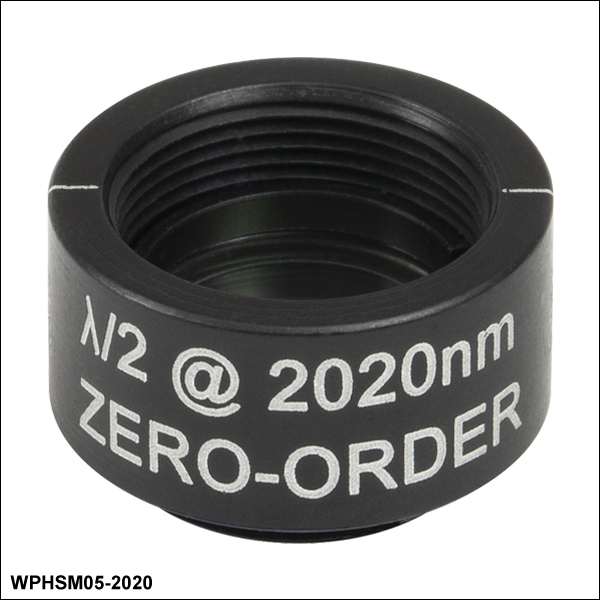
ゼロオーダ1/2波長板、SM05マウント付き")
 ズーム
ズーム
これらの波長板の有効径はØ10.0 mmです。SM05内ネジおよび外ネジ付きの筐体に納められています。
| Item # | Specs |
|---|---|
| WPHSM05-266 | |
| WPHSM05-308 | |
| WPHSM05-355 | |
| WPHSM05-405 | |
| WPHSM05-445 | |
| WPHSM05-473 | |
| WPHSM05-488 | |
| WPHSM05-514 | |
| WPHSM05-532 |
| Item # | Specs |
|---|---|
| WPHSM05-546 | |
| WPHSM05-561 | |
| WPHSM05-588 | |
| WPHSM05-633 | |
| WPHSM05-670 | |
| WPHSM05-694 | |
| WPHSM05-780 | |
| WPHSM05-808 | |
| WPHSM05-830 |
| Item # | Specs |
|---|---|
| WPHSM05-850 | |
| WPHSM05-915 | |
| WPHSM05-980 | |
| WPHSM05-1030 | |
| WPHSM05-1053 | |
| WPHSM05-1064 | |
| WPHSM05-1310 | |
| WPHSM05-1550 | |
| WPHSM05-2020 |
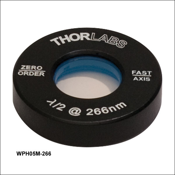
ゼロオーダ1/2波長板、Ø25.4 mmマウント付き")
 ズーム
ズーム
これらの波長板の有効径はØ10.0 mmです。各波長板はØ25.4 mmマウントに取り付けられており、SM1ネジ付き回転マウントに固定リングSM1RRを用いて固定することができます。
| Item # | Specs |
|---|---|
| WPH05M-266 | |
| WPH05M-308 | |
| WPH05M-355 | |
| WPH05M-405 | |
| WPH05M-445 | |
| WPH05M-473 | |
| WPH05M-488 | |
| WPH05M-514 | |
| WPH05M-532 |
| Item # | Specs |
|---|---|
| WPH05M-546 | |
| WPH05M-561 | |
| WPH05M-588 | |
| WPH05M-633 | |
| WPH05M-670 | |
| WPH05M-694 | |
| WPH05M-780 | |
| WPH05M-808 | |
| WPH05M-830 |
| Item # | Specs |
|---|---|
| WPH05M-850 | |
| WPH05M-915 | |
| WPH05M-980 | |
| WPH05M-1030 | |
| WPH05M-1053 | |
| WPH05M-1064 | |
| WPH05M-1310 | |
| WPH05M-1550 | |
| WPH05M-2020 |
ゼロオーダ1/2波長板、SM1マウント付き")
 ズーム
ズーム
これらの波長板の有効径はØ22.6 mmです。SM1内ネジおよび外ネジ付きの筐体に納められています。
| Item # | Specs |
|---|---|
| WPH10M-266 | |
| WPH10M-308 | |
| WPH10M-355 | |
| WPH10M-405 | |
| WPH10M-445 | |
| WPH10M-473 | |
| WPH10M-488 | |
| WPH10M-514 | |
| WPH10M-532 |
| Item # | Specs |
|---|---|
| WPH10M-546 | |
| WPH10M-561 | |
| WPH10M-588 | |
| WPH10M-633 | |
| WPH10M-670 | |
| WPH10M-694 | |
| WPH10M-780 | |
| WPH10M-808 | |
| WPH10M-830 |
| Item # | Specs |
|---|---|
| WPH10M-850 | |
| WPH10M-915 | |
| WPH10M-980 | |
| WPH10M-1030 | |
| WPH10M-1053 | |
| WPH10M-1064 | |
| WPH10M-1310 | |
| WPH10M-1550 | |
| WPH10M-2020 |