 Products Home
チャープミラー、超短パルス分散補償用
- Corrects for Dispersive Optical Elements
- Low AOI Allows Multiple Reflections Between Mirrors
- R > 99% for 650 - 1050 nm or 700 - 1000 nm
- Complementary Mirror Pair Available
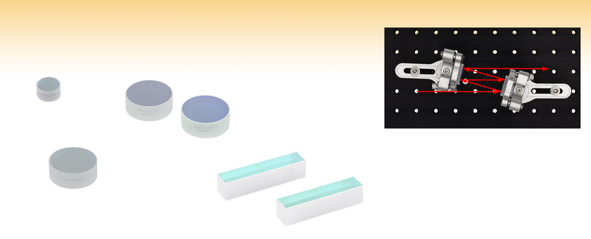
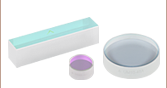
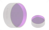
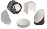
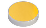
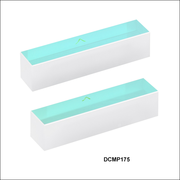
DCMP175
53.0 mm x 12.0 mm, Designed for Multiphoton Microscopy
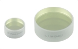
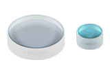
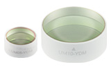
UMC10-15FS
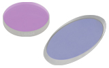
Ø1", Compensates for
1.5 mm of Fused Silica
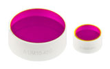
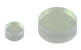
UMC05-15FS
Ø1/2", Compensates for
1.5 mm of Fused Silica
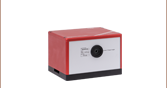
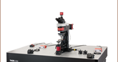
Application Idea
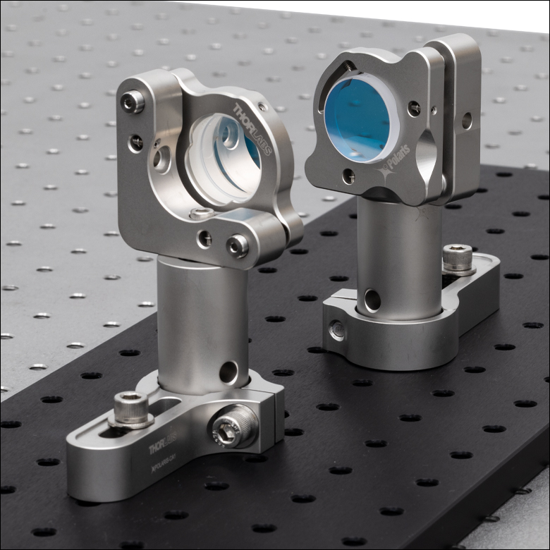
UMCP10-3FS1 Chirped Mirror Pair in POLARIS-K1E2 Mounts Set Up in a Multi-Pass Configuration
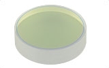
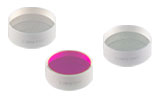
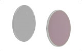
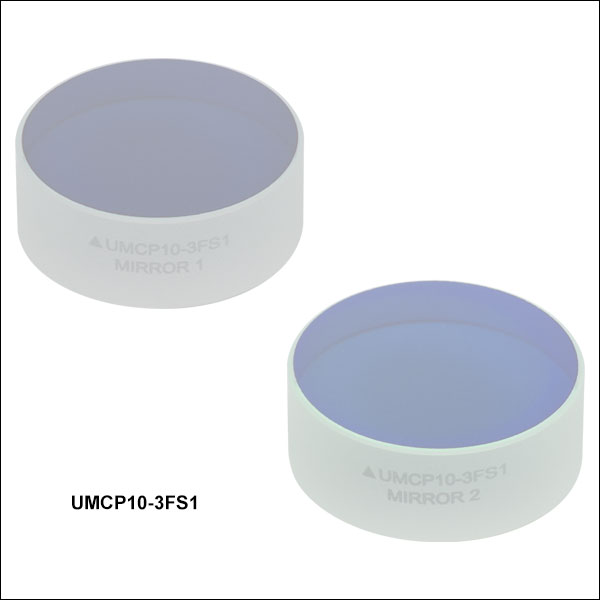
UMCP10-3FS1
Complementary Ø1" Mirror Pair, Compensates for
3.0 mm of Fused Silica


Please Wait
Click to Enlarge
Figure 1.1 2つのミラーマウントPOLARIS-K1E2にそれぞれチャープミラーUMCP10-3FS1を取り付け、レーザ光が各ミラーに入射角10°で入射して、1枚あたり2回反射されるように設定されています。マウントPOLARIS-K1C4のようなクリアエッジの接着式マウントを使用すると、各ミラーでの反射回数を最大化することができます。
特長
- 次のような光学素子の透過光に生じる群遅延分散(GDD)の補償用として設計されたチャープミラー
- UMCx-15FS: 1.5 mmの溶融石英の透過光(ミラー1枚で補償)
- UMCP10-3FS1: 3.0 mmの溶融石英の透過光(ミラーペアで補償)
- DCMP175: 4.8 mmの溶融石英の透過光(ミラー1枚で補償)
- 高い反射率と小さい入射角(AOI)により多重反射が可能になり、補償性能が向上
当社の分散補償ミラーは、超短パルスが分散媒質を伝搬するときに発生するパルス伸長(pulse stretching)の補償用にご利用いただけます。超短パルス光学系で使用される最も一般的な光学基板は溶融石英です。当社のチャープミラーは、この溶融石英を透過する際に生じるパルスの分散を補償するように設計されています。製品としては、単体の円形ミラー、超短パルスを忠実に圧縮するように設計されたマルチパス構成に適した相補型の円形ミラーペア(型番UMCP10-3FS1)、および長方形ミラーの3種類をご用意しています。チャープミラーは、第2高調波発生(SHG)、光パラメトリック発振(OPO)、光パラメトリック増幅(OPA)などの非線形相互作用に超短パルスをご利用になる際に、事前にパルスを圧縮するためにご利用いただくこともできます。また、多光子顕微鏡における長い光路長の補償用としてもご利用いただけます。相補型ミラーペアは、ミラーコーティングによって生じるGDDのリップルが補償されるため、広帯域と波長可変の両方のレーザを使用する用途に適しています。単体のミラー(型番UMCxx-15FS)は波長可変の狭帯域レーザにはあまり適していません。これは、レーザパルスを動作範囲内で走査する際にGDDが大きく変化するためです。単体のチャープミラーと相補型チャープミラーペアの性能の比較は、「GDD補償」タブをご覧ください。
フェムト秒レーザのパルスは多くの異なる波長の光で構成されているため、パルスがガラスのような誘電体を透過するときにパルス伸長(強度プロファイルが時間的に引き延ばされること)が生じます。これは光が透過する光学素子の屈折率が波長に依存すること、すなわち分散によるものです。ほとんどの分散媒質における屈折率は、長波長よりも短波長の方が大きいため、短波長側の光が遅延します。こちらのミラーは、長波長の方が短波長よりも群遅延が大きくなるように設計されており、それにより分散媒質を透過した際に生じた群遅延分散(GDD)を補償します。群遅延および群遅延分散についての詳細は「GDD補償」タブをご覧ください。当社の分散測定システムChromatis™を使用すると、群遅延、群遅延分散、3次分散、4次分散を測定して、光学部品の分散特性を評価できます。Chromatis™システムの製品ページの「動作」タブで、群遅延および群遅延分散についての補足情報をご覧いただけます。
これらのミラーのコーティングは、イオンビームスパッタリング(IBS)により表面に蒸着されています。この再現性と制御性の高い手法により、耐久性のある薄膜コーティングが得られています。超短パルスレーザに使用することを想定して設計されたこれらのコーティングは、高い反射率と高い損傷閾値を有し、当社のChromatis™システムを用いて測定した結果はGDDの理論性能と良く一致しています。
当社のチャープミラーは、設計入射角で使用した場合に優れた性能を発揮しますが、それより小さな入射角でも使用可能です。当社のすべてのチャープミラーは、溶融石英によって発生する正のGDDを補償するよう設計されていますが、他の媒質によって生じる正のGDDも補償することができます。他の一般的な光学ガラスのGDDはこれらのミラーで補償できますが、高次分散項(例えば3次分散など)は完全には補償できません。これはパルス帯域幅によって問題になる場合と、問題にならない場合があります。超短パルス用光学素子のラインナップについては「超短パルス用光学素子」のタブをご覧ください。
| Specifications | ||||
|---|---|---|---|---|
| Item # | UMC05-15FS | UMC10-15FS | UMCP10-3FS1 | DCMP175 |
| Wavelength Range | 650 - 1050 nm | 650 - 1050 nm | 700 - 1000 nm | |
| Reflectance over Wavelength Range | Rabs > 99.5% per Mirror | Rabs > 99.8% per Mirror | Ravg > 99% per Mirror | |
| Reflectance Data (Click for Graph) | Raw Data | Raw Data | Raw Data | |
| Group Delay Data (Click for Graph) | Raw Data | Raw Data | Raw Data | |
| Group Delay Dispersion (GDD) | -54 fs2 at 800 nm per Mirror | -108 fs2 at 800 nm per Mirror Pair | -175 fs2 at 800 nm per Mirror | |
| Group Delay Dispersion (GDD) Data (Click for Graph) | Raw Data | Raw Data | Raw Data | |
| Laser-Induced Damage Threshold | 0.07 J/cm2 (800 nm, 43.2 fs FWHM, S-Pol, 10 000 Pulses)a | 0.05 J/cm2 (800 nm, 49 fs FWHM, P-Pol, 10 000 Pulses)a | 0.10 J/cm2 (800 nm, 100 fs) | |
| Size | Ø1/2" | Ø1" | Ø1" | 53.0 mm x 12.0 mm (2.09" x 0.47") |
| Diameter Tolerance | +0.00 / -0.10 mm | +0.00 / -0.10 mm | N/A | |
| Thickness | 6.35 mm (0.25") | 9.5 mm (0.37") | 9.5 mm (0.37") | 12.0 mm (0.47") |
| Thickness Tolerance | ±0.10 mm | ±0.20 mm | ±0.20 mm | - |
| Clear Aperture | > 80% of Diameter | > 80% of Diameter | At Least 8 mm x 50 mm | |
| Angle of Incidence (AOI) | 10° | 10° | 8° | |
| Surface Flatnessb | λ/4 at 632.8 nm Over Clear Aperture | λ/4 at 632.8 nm Over Clear Aperture | λ/10 at 633 nm Over Any Ø8 mm in the Clear Aperture | |
| Surface Quality (Front Surface) | 15-5 Scratch-Dig | 15-5 Scratch-Dig | 10-5 Scratch-Dig | |
| Back Surface | Polished | Polished | - | |
| Substrate | Fused Silica | Fused Silica | Fused Silica | |
| Parallelism | ≤3 arcmin | ≤3 arcmin | - | |
分散補償の仕組み
レーザパルスが分散媒質を透過するとき、媒質により分散が発生します。ほとんどの分散媒質では、650~1000 nmの波長範囲で正の群遅延分散(GDD)が生じます。正の分散媒質を透過したパルスでは、パルス内の短波長(青色側)の光は長波長(赤色側)の光よりも遅れます。逆に負の分散媒質を透過したパルスでは、長波長(赤色側)の光が短波長(青色側)の光よりも遅れます。どちらの場合も、試料内でレーザパルスの幅が広がり、ピーク強度は低下します。
当社のチャープミラーは、波長範囲650~1050 nm(型番UMCxx-15FS、UMCP10-3FS1)または700~1000 nm(型番DCMP175)のパルスに対して、負の群遅延分散(GDD)を生じさせます。これらのチャープミラーは、それぞれの仕様波長範囲において、溶融石英によって生じた正のGDDを補償するよう設計されていますが、他の媒質によって生じた正のGDDも補償することができます。これらのミラーの性能についての詳細は「仕様」タブをご覧ください。
Figure 3.1は、正の群遅延分散をチャープミラーで補償する例を示しています。チャープミラーは、群遅延分散の前置補償用または後置補償用として、分散素子の前または後に配置して使用することができます。
Figure 3.1 チャープミラーを用いた正のGDDの補償例
チャープミラーの比較
広帯域のチャープミラーでは、コーティングの設計に起因するGDD振動(GDD oscillation)が常に発生し、それにより衛星パルス(satellite pulse)が出現します。同一のミラーを2枚使用したとき、両ミラーのコーティングによって生じるパルスのGDD振動は同位相になるため、衛星パルスは建設的に干渉します(Figure 3.2参照)。しかし、相補型ミラーペア(型番UMCP10-3FS1)のコーティングは振動が逆位相となるように設計されているため、衛星パルスは破壊的に干渉してほぼ除去されます。Figure 3.3、3.4では、パルスが15 mmの溶融石英を透過したときに生じるGDDを補償するために、同じミラーUMCxx-15FSを2枚使用したときと、相補型チャープミラーペアUMCP10-3FS1を使用したときの、パルスの時間プロファイルを比較しています。
Click to Enlarge
Figure 3.2 同じチャープミラー2枚を用いたときと、相補型チャープミラーペアを用いたときのパルス伝搬の比較
Click to Enlarge
Figure 3.3 チャープミラーUMCxx-15FSと相補型チャープミラーペアUMCP10-3FS1の比較。元のパルス、15 mmの溶融石英(ビームスプリッタUFPBS10Aなど)を透過後のパルス、15 mmの溶融石英と2枚のミラーUMCxx-15FS(ミラー1枚あたり5回の反射)を透過後のパルス、15 mmの溶融石英とミラーペアUMCP10-3FS1(ペアで5回の反射)を透過後のパルスの各時間プロファイルを示しています。チャープミラーペアUMCP10-3FS1を使用すると、時間プロファイルが保持され、また衛星パルスも抑制されます。
Click to Enlarge
Figure 3.4 チャープミラーUMCxx-15FSと相補型チャープミラーペアUMCP10-3FS1の比較。元のパルス、15 mmの溶融石英(ビームスプリッタUFPBS10Aなど)を透過後のパルス、15 mmの溶融石英と2枚のミラーUMCxx-15FS(ミラー1枚あたり5回の反射)を透過後のパルス、15 mmの溶融石英とミラーペアUMCP10-3FS1(ペアで5回の反射)を透過後のパルスの各時間プロファイルを示しています。チャープミラーペアUMCP10-3FS1を使用すると、時間的プロファイルが保持され、また衛星パルスも抑制されます。
| Posted Comments: | |
Hyun Sung Lee
(posted 2025-06-20 15:31:19.71) Dear THORLABS,
I found chirped mirror UMC05-15FS in your website, and I want to know a raw data for the phase graph of mirror, not the gdd graph.
Is it possible to get the data?
Thank you,
Hyun Sung Lee EGies
(posted 2025-06-30 01:09:08.0) Thank you for contacting Thorlabs. I have reached out to you directly regarding the theoretical phase data for the UMC05-15FS. To request additional specs and data, you can email us at techsupport@thorlabs.com. user
(posted 2025-02-21 04:22:03.39) 有不同波长处的GDD曲线吗 cdolbashian
(posted 2025-03-20 01:36:08.0) Thank you for reaching out to us with this inquiry. I have contacted you directly to share the GDD data as you requested. Lukasz Piatkowski
(posted 2023-10-09 10:27:14.27) Hi,
I'm looking for dispersion compensating optics to deal with dispersion in the range 600-700 nm in the laser pulses coming from a white light laser source (NKT Fianium). What is the reflectivity/dipsersion compensation characteristic of your DCMP175 in the mentioned range?
With best wishes,
Lukasz cdolbashian
(posted 2023-10-20 10:37:27.0) Thank you for reaching out to us with this inquiry. Unfortunately, these mirrors are not meant to be used <650nm as this is outside the design wavelength range. The in-range performance can be found in the "graphs" tab above. In the case you do decide to use them within this range, you will likely experience inconsistent performance from unit to unit, due to the above design consideration. XinWei Yi
(posted 2023-04-01 16:00:55.72) I want to know the group delay dispersion (GDD) curve of UMC10-15FS at zero Angle of incident. cdolbashian
(posted 2023-04-26 10:01:00.0) Thank you for reaching out to us with this inquiry. Unfortunately we do not have such data to share. we would estimate a redshift of about 2% with respect to the values we have posted for the 10° AOI. Cheng Zong
(posted 2022-03-18 13:30:38.39) Hi, I find the DCMP175 surface is dusty. How to clean it? Can I use methanol or acetone to clean it? ksosnowski
(posted 2022-03-22 05:33:05.0) Hello Cheng, thanks for reaching out to Thorlabs. We recommend light dusting with clean, dry air first to remove the largest particles. If solvent is needed to wipe the surface, you can use acetone, methanol, or isopropanol to clean this as the chirped mirror pair is not cemented. We offer lens wipes MC-5 and cleaning accessories to aid in this as well. It may be slightly easier to avoid streaks with isopropanol, as it dries slightly slower allowing a slower, more even wiping motion. Hendrik Wrigge
(posted 2021-12-08 08:31:59.49) Using the UMC10-15FS mirrors, I noticed a slight ellipticity in polarisation after my mirror compressor. The initial beam bevore the mirrors is strictly linear polarized.
Inside the compressor, I use 16 reflections on the UMC10-15FS.
Is this a standart behavior of your mirror or do you have any coment on this?
Thank you in advance cdolbashian
(posted 2021-12-22 04:29:22.0) Thank you for contacting us here at Thorlabs. We have not characterized the reflection-induced-polarization states for these mirrors. Theoretically though, if your polarization state was not completely within, or orthogonal to, the incident plane, you may see a slight ellipticity in your reflected beam, especially after 16 bounces. Based on our discussion it seemed that there was a bit of misalignment between the incident plane and the direction of linear polarization (~.5deg). Correcting this error solved the problem which you were seeing. Thank you again for reaching out to us and allowing me to help you work through this problem. Audrius z
(posted 2020-09-30 08:28:56.68) Hello, could please send me the GDD curve for these chirped mirrors?
Best YLohia
(posted 2020-10-01 03:57:11.0) Hello, thank you for contacting Thorlabs. Which specific mirror are you referring to? One can calculate this from the raw group delay data (found on the Graphs tab) by taking the derivative. I have reached out to you directly to discuss this further. Ondrej Novak
(posted 2019-10-11 17:48:54.953) Dear colleagues, could you please provide us with a graph of DCMP175 GDD compensation performance over different wavelength? Such curve would be extremely helpful. I am especially interested in wavelengths from 920nm to 1040nm. How much fs2 can be compensate per single bounce? Thank you.
Ondrej YLohia
(posted 2019-10-22 10:12:15.0) Hello Ondrej, thank you for contacting Thorlabs. The GDD for the DCMP175 is nominally -175 fs^2 at 800 nm but it changes a little with wavelength and has fairly large oscillations. I have reached out to you directly with some GDD data that we have up to 1000 nm. The oscillations become very large outside the design range. That's typical for all dielectric coatings, not just these chirped mirrors. We do not recommend using these at >1000 nm. yuezhu
(posted 2017-12-18 12:46:27.343) Can I use chirped mirrors in optical coherence tomography system?
How about https://www.thorlabs.com/newgrouppage9.cfm?objectgroup_id=3242 ?
Which one is better? tfrisch
(posted 2018-03-22 12:16:19.0) Hello, thank you for contacting Thorlabs. Chirped mirrors and dispersion compensating prisms are both used to adjust for chromatic dispersion. Which one is better suited for your application will depend on how you intend to use these. I will contact you directly about your application. dtorchin
(posted 2017-12-06 18:32:00.957) Individual chirped mirrors have GD oscillations as a function of wavelength. Is DCMP175 sold as a pair whose oscillations cancel? llamb
(posted 2018-03-01 08:12:47.0) Hello, thank you for contacting Thorlabs. DCMP175 is indeed sold as a pair of mirrors. The oscillations will not cancel, but each reflection will add to the Group Delay Dispersion. The mirrors can be adjusted to increase/decrease the number of reflections, thus increasing/decreasing the GDD as needed for the application. pedro.oliveira
(posted 2017-10-24 18:52:36.55) Dear Sir/Madam,
I would like to have the data for the reflectance and the GD for DCMP175?
Many thanks,
Pedro Oliveira tfrisch
(posted 2017-10-30 01:55:22.0) Hello, thank you for contacting Thorlabs. We will reach out to you directly with theoretical data in tabular form that can be used for your calculations. t.wills
(posted 2017-01-27 05:41:00.78) Dear Thorlabs,
Do you have a number available for the GDD per reflection at 940nm? This would be the wavelength I need to use.
I am confused by the graph showing 'GD' versus wavelength - 'GD' appears to go positive at wavelengths >850nm, which means the mirror wouldn't work for pre-compensation (but I suspect I haven't understood the graph).
Many thanks,
Tom tfrisch
(posted 2017-02-17 02:34:05.0) Hello, thank you for contacting Thorlabs. GD and GDD are related by a derivative. I will contact you directly with more details, but the zero of GD is chosen only as a reference. user
(posted 2013-08-23 10:41:42.49) Is there a recommended maximum distance between the mirrors, a maximum incidence angle or a maximum number of reflexions to consider? Is there an app note or recommendations on using these? Thank you. jlow
(posted 2013-08-29 13:18:00.0) Response from Jeremy at Thorlabs: The recommended maximum angle of incidence (AOI) is about 7°. The correct mirror distance depends on the number of bounces needed. Depending on the wavelength of the laser used, the tolerable AOI can be different as well. We have some plots (for s- and p-polarization) showing the evolution of the calculated GDD in the specified wavelength range as a function of AOI. As a general rule of thumb, the maximum AOI is smaller if the laser wavelength is longer. For example, around 20° AOI might be useable for 750-800nm light but around 10° AOI might be useable for 900-950nm light. However, it should be noted that the performance is not guaranteed for large AOIs. Since you did not leave your e-mail address, can you contact techsupport@thorlabs.com please? We can discuss about this further via e-mail. tcohen
(posted 2012-05-16 13:45:00.0) Response from Tim at Thorlabs: Thank you for contacting us Jan Metje! Our baseline LIDT for the DCMP is 0.1J/cm^2 for 100fs pulses at 100Hz. Please note that for shorter pulses and higher repetition rates the damage threshold will be smaller. jan.metje
(posted 2012-05-15 07:57:14.0) Dear Sir or Madam,
do you know the damage threshold of this dispersion comensating mirror set?
Kind regards,
Jan Metje bdada
(posted 2011-10-12 19:22:00.0) Response from Buki at Thorlabs:
The DCMP175 Dispersion-Compensating Mirrors can be mounted in the KM100C Kinematic Cylindrical Lens Mount. The mount accepts any cylindrical or rectangular optic up to 65 mm tall.
The mount can be attached to any of Thorlabs' Ø1/2" TR Series posts, which feature an #8-32 (M4) tapped hole. Alternatively, the KM100C mount can also be attached to an RS1.5P Ø1" Pedestal Pillar Post, which has a height of 1.5", and can be secured to the breadboard using a CF125 Clamping Fork.
Alternatively, these mirrors can be mounted in the Kinematic Grating Mount Adapter,KGM20, KGM40, or KGM60 which is compatible with Ø1", front-loading, unthreaded mirror mounts.
Please contact TechSupport@thorlabs.com if you have further questions. zacarias.garcia
(posted 2011-10-12 08:52:58.0) Could you please tell us how and where to install these mirrors ? |
フェムト秒パルスレーザ用ならびにピコ秒レーザ用光学素子を幅広くご用意しています。詳細は下表をご参照ください。
| Dielectric Mirror | High-Power Mirrors for Picosecond Lasers | Metallic Mirrors | Low-GDD Pump-Through Mirrors | ||
|---|---|---|---|---|---|
 |  |  |  |  |  |
| Dual-Band Dielectric Mirror, 400 nm and 800 nm | Ytterbium Laser Line Mirrors, 250 nm - 1080 nm | Ultrafast-Enhanced Silver Mirrors, 750 - 1000 nm | Protected Silver Mirrors, 450 nm - 20 µm | Unprotected Gold Mirrors, 800 nm - 20 µm | Pump-Through Mirrors, 1030 - 1080 nm and 940 - 980 nm |
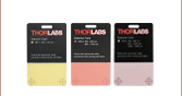
| Deterministic GDD Beamsplitters | Low-GDD Harmonic Beamsplitters | Low-GDD Polarizing Beamsplitters | β-BBO Crystals | Dispersion-Compensating Optics | |
|---|---|---|---|---|---|
 |  |  |  |  |  |
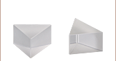
| Beamsplitters & Windows, 600 - 1500 nm or 1000 - 2000 nm | Harmonic Beamsplitters, 400 nm and 800 nm or 500 nm and 1000 nm | High-Power, Broadband, High Extinction Ratio Polarizers, 700 - 1300 nm | β-BBO Crystals for Second Harmonic Generation | Dispersion-Compensating Mirrors, 650 - 1050 nm | Dispersion-Compensating Prisms, 700 - 900 nm |
またはØ25.4 mm(Ø1インチ)")
 ズーム
ズーム Click to Enlarge
- ミラー1枚あたりの絶対反射率:>99.5%(650~1050 nm)
- ミラー1枚あたりの群遅延分散(GDD):厚さ-1.5 mmの溶融石英に相当
- 有効径:>直径の80%
- 入射角10°
- スペクトル幅>50 nm(FWHM)のパルス用に設計
当社のチャープミラーUMC05-15FSおよびUMC10-15FSの1枚あたりの反射率は、650~1050 nmにおいて>99.5%です。このコーティングは、1.5 mmの溶融石英によって生じる仕様波長範囲内の分散を、1回の反射で補償するように設計されています。このミラー1枚で生じる平均GDDの設計値は-54 fs2です。これは、波長800 nmにおいて1.5 mmの溶融石英で生じるGDDを補償するのに適した値です。10°の入射角では、ミラーはS偏光とP偏光のどちらでも同様に機能します。またこの入射角は多重反射を必要とするコンパクトなセットアップに適しています。こちらのミラーの性能についての詳細は「仕様」タブをご覧ください。
取付け方法
Ø12.7 mm(Ø1/2インチ)ミラーの厚さは6.35 mm、Ø25.4 mm(Ø1インチ)ミラーの厚さは9.5 mmです。マルチパスを構成するときにクリアエッジを最大化するために、UMC105-15FSは接着式ミラーマウントPOLARIS-K05C4に、UMC10-15FSは接着式キネマティックミラーマウントPOLARIS-K1C4に取り付けることをお勧めします。
")
 ズーム
ズーム Click to Enlarge
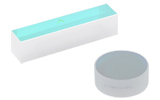
- 超短パルス用に設計された相補型チャープミラーペア
- ミラー1枚あたりの絶対反射率:>99.8%(650~1050 nm)
- ミラーペアあたりの群遅延分散(GDD):厚さ-3.0 mmの溶融石英に相当
- 有効径:>直径の80%
- 入射角10°
- 広帯域または狭帯域の超短パルス用に設計
当社の相補型チャープミラーペアUMCP10-3FS1は、超短パルスを忠実に圧縮するように設計されています。ミラー1枚あたりの絶対反射率は、650~1050 nmにおいて>99.8%です。この相補型チャープミラーペアと単体のチャープミラー(型番UMCxx-15FS)の性能の比較については、「GDD補償」タブをご覧ください。ミラーのコーティングは、650~1050 nm範囲において3.0 mmの溶融石英を透過したときに生じる分散を、このミラーペアによる反射で補償するよう設計されています。このミラーペアで生じる平均GDDの設計値は-108 fs2です(Figure G2.1参照)。これは、波長800 nmにおいて3.0 mmの溶融石英で生じるGDDを補償するのに適した値です。10°の入射角では、ミラーはS偏光とP偏光のどちらでも同様に機能します。またこの入射角は多重反射を必要とするコンパクトなセットアップに適しています。こちらのミラーの性能についての詳細は「仕様」タブをご覧ください。
取付け方法
こちらのミラーの厚さは9.5 mmです。マルチパスを構成するときにクリアエッジを最大化するために、ミラーUMCP10-3FS1は接着式キネマティックミラーマウントPOLARIS-K1C4に取り付けることをお勧めします。

 ズーム
ズーム
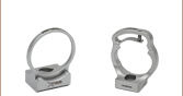
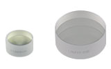
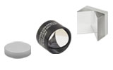
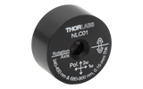
Click to Enlarge
Figure G3.1 アダプタKGM20を使用してミラーマウントに取り付けられた1枚のDCMP175
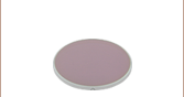
- ミラー1枚あたりの平均反射率:>99%(700~1000 nm)
- ミラー1枚あたりの群遅延分散(GDD):厚さ-4.8 mmの溶融石英に相当
- コーティング面の寸法:50 mm x 8 mm
- 入射角8°
- スペクトル幅>50 nm(FWHM)のパルス用に設計
- 2個セットでご提供
DCMP175は、波長範囲700~1000 nmにおける平均反射率>99%(ミラー1枚あたり)の2つの長方形光学素子で構成されています。一般に多光子顕微鏡は分散性の高いガラスを透過する長い光路を有しますが、こちらのミラーはそのようなセットアップに組み込むように設計されています。このミラー1枚で生じる平均GDDの設計値は-175 fs2です。これは、波長800 nmにおいて4.8 mmの溶融石英で生じるGDDを補償するのに適した値です。8°の入射角では、ミラーはS偏光とP偏光のどちらでも同様に機能します。またこの入射角は多重反射を必要とするコンパクトなセットアップに適しています。
取付け方法
これらのミラーは、Figure G3.1のように回折格子用キネマティックマウントアダプタに取り付けることができます。また、このアダプタは当社のPolaris低ドリフトミラーマウントのような、Ø25.4 mm(Ø1インチ)、前面取り付け、ネジ切り無しのミラーマウントに取り付けられます。