 Products Home / オプトメカニクス用部品 / マウント / ミラーマウント(ミラーホルダ) / Polaris®ミラーマウント / SMネジ付きPolarisミラーマウント / Polaris®KAマウント、SM1ネジホールドタイプ、Ø25.4 mm(Ø1インチ)光学素子用
Polaris®KAマウント、SM1ネジホールドタイプ、Ø25.4 mm(Ø1インチ)光学素子用
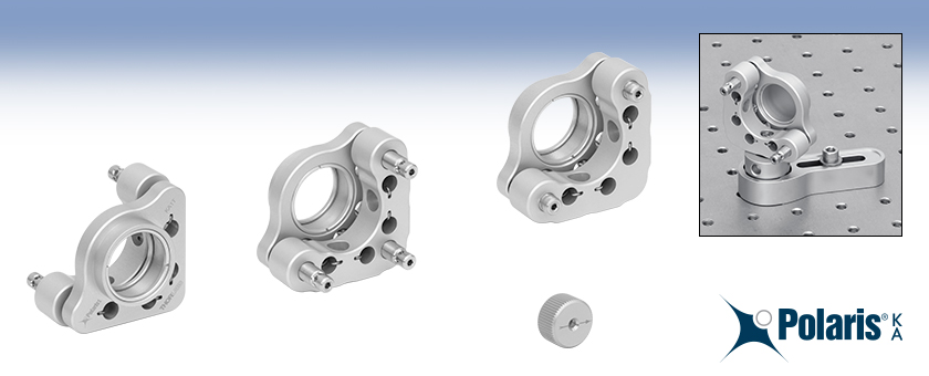
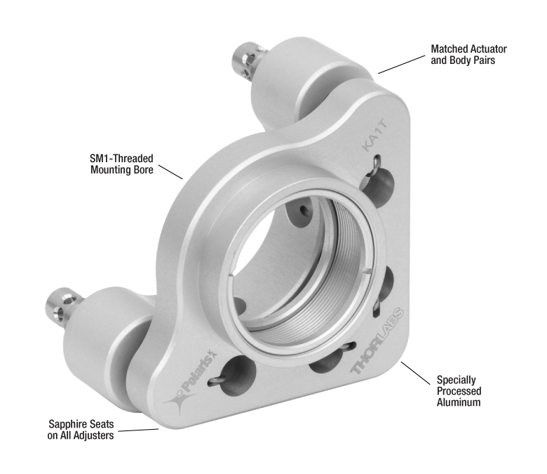
- SM1-Threaded Mounting Bore
- Matched Actuator and Back Plate Threading Minimize Drift and Backlash
- Lightweight Aluminum Front and Back Plates
- Sapphire Adjuster Seats Prevent Wear Over Time
Sapphire Adjuster Seats Prevent Wear Over Time
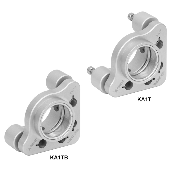
KA1T
2 Adjusters with Side Holes
KA1TA
3 Adjusters with Side Holes
KA1TB
2 Low-Profile Adjusters
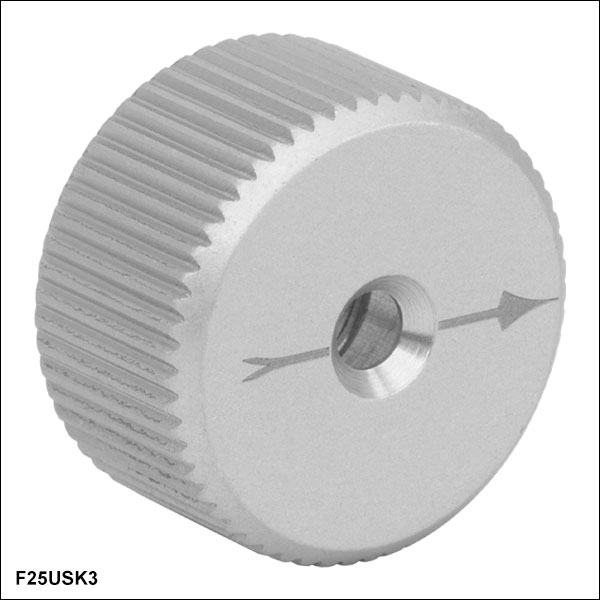
F25USK3
Aluminum Removable Knob for 1/4"-100 Adjusters
Application Idea
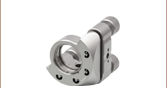
KA1T Ø1" Mirror Mount with Mirror on a Ø1" Post for Polaris Mounts


Please Wait
Click to Enlarge
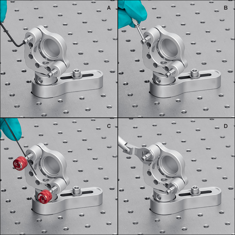
Figure 1.1 Ø25.4 mm(Ø1インチ)光学素子用マウントKA1Tの調整方法
A: 2.0 mm六角レンチをアジャスタの先端に挿入して調整
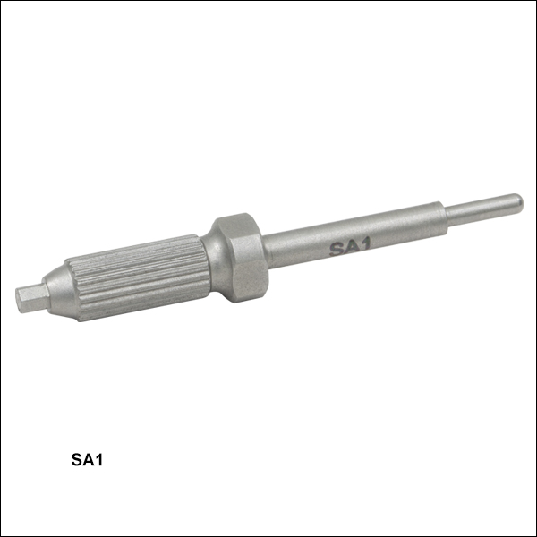
B: 調整ツールSA1をアジャスタのサイドホールに挿入して調整
C: 六角ノブHKTS-5/64とサイドホールに挿入した1.5 mmボールドライバを使用して精密調整
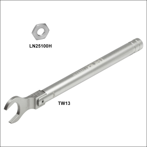
D: トルクレンチTW13を使用してロックナットLN25100H を固定
| Quick Links |
|---|
| Ø1" Mounts with 3 Adjusters |
| Ø1" Mounts with 2 Adjusters |
| Removable Adjuster Knob |
| Hex Adjusters |
| Side Hole Adjustment Tool |
| Lock Nut & Torque Wrench |
| Locking Collar & Spanner Wrench |
Click to Enlarge
Figure 1.2 PolarisKAシリーズマウントは様々な温度試験を経て、その高い性能が実証されています。試験結果は「試験データ」タブをご覧ください。
特長
- 時効処理された7075アルミニウム合金から機械加工により製作され、引張強度、剛性、表面靭性、寸法安定性などで優れた特性
- 高い耐久性と滑らかな動きを実現するために、硬化処理ステンレススチール製ボールとの接点にはサファイアシートを使用
- 整合したアクチュエータと背面プレートにより、安定性と滑らかなキネマティック調整を実現
- 様々な試験により、温度幅15 °Cの温度サイクル後の角度変化として4 μrad未満を保証(詳細は「試験データ」タブ参照)
- 真空用および高出力レーザ共振器用として設計された製品で、特殊アルマイト処理されたフレームと不動態化処理されたステンレススチール製アジャスタで構成
- 汚染を低減するバネの設計(特許申請中)
- 取付け穴を選ぶことで、右手系または左手系の選択が可能
- カスタム仕様のマウントについては当社までお問い合わせください。
Polaris®KAシリーズ低ドリフトキネマティックミラーマウントは、低ドリフト特性が得られるように設計されており、材料には白色アルマイト処理された7075アルミニウムが使用されています。そのため、アライメントの長期安定性を必要とする産業分野での使用に適しています。
光学素子の保持
これらのØ25.4 mm(Ø1インチ)光学素子用ミラーマウントの光学素子取付け穴にはSM1内ネジが付いており、様々な光学素子を取り付けることができます。各マウントには、白色アルマイト加工のアルミニウム製固定リングが2個付属しています。この固定リングは別途追加購入されることも可能です。
Polarisミラーマウントの光学素子取付け穴は、温度変化や移動時の衝撃・振動など、様々な環境変化に対して最良のビームポインティング安定性が得られるように精密加工されています。しかし、Ø25.4 mm(Ø1インチ)マウントにØ25 mm光学素子や外径公差が0より大きい光学素子を取付けた場合には、その性能は低下してしまいます。
設計
時効処理された軽量の7075アルミニウム合金から機械加工されたPolarisKAシリーズマウントには、ボール接触やサファイアシートを用いて精密に整合されたアジャスタが使用されているため、滑らかなキネマティック調整が可能です。「試験データ」タブでご覧いただけるように、これらのマウントは様々な試験により、その高い性能が実証されています。Polaris製品は、ビームに生じるミスアライメントの一般的な要因にすべて対応するように設計されています。詳しくは「設計の波長」タブをご覧ください。
ポストへの取り付け
PolarisKAシリーズミラーマウントには、ポストに取り付けるためのM4用ザグリ穴があります。推奨する取付け方法等については「使用方法」タブをご覧ください。
クリーンルームおよび真空への対応について
全てのPolarisKAシリーズマウントはクリーンルームや真空で使用できるように設計されており、最高ベークアウト温度および最高動作温度は80°Cです。詳細は「仕様」タブおよび「設計の波長」タブをご覧ください。
PolarisKAシリーズマウントの前面および背面のアルミニウム製プレートは、酸エッチング、特殊アルマイト処理による5 µmの薄い酸化皮膜形成、ニッケルによる2重シール形成などの工程の後、逆浸透脱イオン水(RODI)による煮沸処理が施されています。この工程により、金属全体に清浄性、滑らかさ、薄さ、硬さ、無孔性などの特性面で優れた表面が形成され、また酸化膜によって密封されます。これと同じ表面処理は、一部の真空チャンバーメーカでも、裸のアルミニウムの表面に自然酸化膜が形成されるのを防止するために使用されています。この表面仕上げでは、標準的なアルマイト処理よりも優れた表面特性が得られます。PolarisKAシリーズマウントに対しては、最高ベークアウト温度を80 °C以下に抑えることを推奨しています。詳細は「仕様」タブをご覧ください。
超高真空(UHV)システム内でのアウトガスの発生をさらに低減するために、裸のアルミニウムに酸エッチングのみを施した部材で組み立てたマウントも、ご要望に応じてご提供可能です。ご要望の際は、当社までお問い合わせください。表面硬度が低下するため、これらのマウントの表面の強靭さは低下し、それに伴ってレンズセルやアジャスターネジの摩耗が早くなります。このようなマウントでは、表面汚染や自然酸化膜の形成を防ぐためにも、取扱いと保管は慎重に行う必要があります。一方、このようなカスタムマウントでは、ベークアウト温度を最高200 °Cまで上げることができます。
超高真空(UHV)システムで最もアウトガスの少ないマウントを使用したい場合は、当社のPolaris製品のラインナップの中のステンレススチール製マウントをご検討ください。これらはベークアウト温度を最高200 °Cまで上げることができます。
| Item # | KA1TA | KA1T | KA1TB |
|---|---|---|---|
| Optic Sizea | Ø1" | ||
| Optic Thickness (Max) | 0.34" (8.6 mm) | ||
| Number of Adjusters | Three | Two | Two, Low Profile |
| Adjuster Drive | 5/64" (2.0 mm) Hex, Ø0.07" Side Adjustment Holes | 5/64" (2.0 mm) Hex | |
| Adjuster Thread | 1/4"-100 | ||
| Actuator Matching | Matched Actuator/Body Pairs | ||
| Measured Point-to-Point Mechanical Resolution per Adjuster | 5 µrad (Typical); 2 µrad (Achievable) | ||
| Adjustment Resolutionb | ~7.7 mrad/rev | ||
| Mechanical Angular Range (Nominal) | ±4° | ||
| Front Plate Separation at Pivot Adjuster | 3.175 mm (Nominal) | ||
| Front Plate Translation (Max) | 6 mm | N/A | |
| Beam Deviationc After Thermal Cycling | < 4 μrad | ||
| Recommended Optic Mounting Torqued | 5 - 7 oz-in for 6 mm Thick UVFS Optics | ||
| Maximum SM-Threaded Component Mounting Torque | 30 lb-in for SM1-Threaded Parts | ||
| Maximum Front Plate Payload (Torque / Weight) from Mounted Components | 1 lb-in (0.11 N·m) / 1 lb (4.5 N) | ||
| Mounting | Two #8 (M4) Counterbores at 90° | ||
| Cleaninge | Adjuster screws are passivated per ASTM-967; Frames are acid etched, anodized to MIL-A-8625, Type 2, Class 1, with a thin dense oxide layer and duplex sealed using nickel followed by boiling in reverse osmosis deionized (RODI) water. | ||
| Vacuum Compatibilityf | 10-9 Torr at 25 °C with Proper Bake Out 10-5 Torr at 25 °C without Bake Out Grease Vapor Pressure: 10-13 Torr at 20 °C; 10-5 Torr at 200 °C Epoxy Meets Low Outgassing Standards NASA ASTM E595, Telcordia GR-1221 | ||
| Mass (Weight) | 69 g (2.4 oz) | 65 g (2.3 oz) | 62 g (2.2 oz) |
| Operating Temperature Range | -30 to 80 °C | ||
Polaris®KA Mirror Mount Test Data
All Polaris Low-Drift Kinematic Mirror Mounts undergo extensive testing to ensure high-quality performance. Thermal shock testing confirms the exceptional stability of the mounts and demonstrates that they reliably return to their initial position after a transient temperature shift. Interferometric wavefront distortion testing demonstrates the ability of Polaris mounts to secure an optic without significantly distorting the optical surface.
Video 3.1 Vibration Testing for Polaris Mounts (Ø19 mm Polaris Mount Shown)
Vibration Testing
Purpose: This testing was done to determine how reliably PolarisKA mirror mounts behave when subjected to intense physical vibrations.
Procedure: A pair of identical KA1T mirror mounts were mounted on Ø1" Posts for Polaris Mirror Mounts and secured to a stainless steel breadboard with POLARIS-CA1 clamping arms. Laser beams were reflected from the mirrors onto two position sensing detectors, located on the same breadboard. The entire platform was vibrated with a variable frequency and amplitude, and the displacement of the beam on the detector was recorded. The two beam paths were oriented at right angles so that the vibrational motion was in a direction parallel to the face of one mount and perpendicular to the face of the other. Please see Video 3.1 for a demonstration of our Polaris vibration test (the mount shown in the video is the POLARIS-K19S4 Ø19 mm mount).
Results: When subjected to vibrational frequencies from 5 to 500 Hz and accelerations as high as 6 g, the KA1T mounts remained mechanically sound. The angular position of the mounts remained stable within about 10 µrad for both parallel and perpendicular vibrations.
Conclusions: Our PolarisKA mirror mounts provide exceptional performance, even under rugged operating conditions. As a result, these mounts are ideal for use in systems that require the greatest degree of stability when vibrational noise is expected.
Positional Repeatability After Thermal Shock
Purpose: This testing was done to determine how reliably the mount returns the mirror, without hysteresis, to its initial position. These measurements show that the alignment of the optical system is unaffected by the temperature shock.
Procedure: After attaching the PolarisKA mount to a Ø1" Post, the mirror and post assembly was secured to a stainless steel optical table in a temperature-controlled environment. The mirror was held using the flexure mechanism; see the Usage Tips tab for additional mounting considerations. A beam from an independently temperature-stabilized laser diode was reflected by the mirror onto a position sensing detector. The temperature of each mirror mount tested was raised to at least 37 °C. The elevated temperature was maintained in order to soak the mount at a constant temperature. Then the temperature of the mirror mount was returned to the starting temperature. The results of these tests are shown in Tables 3.2, 3.5, and 3.8.
Results: As can be seen in these plots, when the mount was returned to its initial temperature, the angular position (both pitch and yaw) of the mirrors returned to within 4 µrad of its initial position. The performance of the mount was tested further by subjecting the mount to repeated temperature change cycles. After each cycle, the mirror's position reliably returned to within 4 µrad of its initial position
For Comparison: To get a 4 µrad change in the mount’s position, the 1/4"-100 threaded adjuster on the PolarisKA mount needs to be rotated by only 0.2° (1/1800 of a turn). A skilled operator might be able to make an adjustment as small as 0.3° (1/1200 of a turn), which corresponds to a 6 µrad change in the mount's position.
Conclusions: PolarisKA Mirror Mounts are high-quality, ultra-stable mounts that will reliably return a mirror to its original position after cycling through a temperature change. As a result, PolarisKA mounts are ideal for use in applications that require long-term alignment stability.
| Table 3.2 KA1TA 3-Adjuster Mount with Adjuster Side Holes, SM1 Threaded |
|---|
| Table 3.5 KA1T 2-Adjuster Mount with Adjuster Side Holes, SM1 Threaded |
|---|
| Table 3.8 KA1TB 2-Adjuster Mount with Low-Profile Adjusters, SM1 Threaded |
|---|


Click to Enlarge
Figure 4.1 Design Features of KA1T Series Mounts
Several common factors typically lead to beam misalignment in an optical setup. These include temperature-induced hysteresis of the mirror's position, crosstalk, drift, and backlash. Polaris® mirror mounts are designed specifically to minimize these misalignment factors and thus provide extremely stable performance. Hours of extensive research, multiple design efforts using sophisticated design tools, and months of rigorous testing went into choosing the best components to provide an ideal solution for experiments requiring ultra-stable performance from a kinematic mirror mount.
Thermal Hysteresis
The temperature in most labs is not constant due to factors such as air conditioning, the number of people in the room, and the operating states of equipment. Thus, it is necessary that all mounts used in an alignment-sensitive optical setup be designed to minimize any thermally induced alignment effects. All the critical components of the PolarisKA series mirror mounts are made from specially selected dimensionally stable materials, such as low stress aged round 7075 aluminum bar stock to reduce internal stresses that can cause temperature-dependent hysteresis and optimal material tempers to improve the material stiffness and strength. As a result, the alignment of the optical system will be restored when the temperature of the mirror mount is returned to the initial temperature.
The method by which the mirror is secured in the mount is another important design factor for PolarisKA series mounts; these mounts offer excellent performance without the use of adhesives. Instead, the mounts offered on this page use a monolithic flexure arm that is pressed onto the edge of the mirror using a setscrew. Setscrews, when used by themselves to hold an optic, tend to move as the temperature changes. In contrast, the holding force provided by the aluminum flexure arm is sufficient to keep the mirror locked into place regardless of the ambient temperature.
Crosstalk
Crosstalk is minimized by carefully controlling the dimensional tolerances of the front and back plates of the mount so that the pitch and yaw actuators are orthogonal. In addition, sapphire seats are used at all three contact points. Standard metal-to-metal actuator contact points will wear down over time. The polished sapphire seats of PolarisKA series mounts, in conjunction with the hardened stainless steel actuator tips, maintain the integrity of the contact surfaces over time.
Drift and Backlash
In order to minimize the positional drift of the mirror mount and backlash, it is necessary to limit the amount of play in the adjuster as well as the amount of lubricant used. When an adjustment is made to the actuator, the lubricant will be squeezed out of some spaces and built up in others. This non-equilibrium distribution of lubricant will slowly relax back into an equilibrium state. However, in doing so, this may cause the position of the front plate of the mount to move. PolarisKA series mounts use adjusters matched to the body or bushings that exceed all industry standards so very little adjuster lubricant is needed. As a result, alignment of these mounts is extremely stable even after being adjusted (see the Test Data tab for more information). In addition, these adjusters have a smooth feel that allows the user to make small, repeatable adjustments.
Cleanroom and Vacuum Compatibility
The front and back plates of PolarisKA mounts are machined from aged 7075 aluminum alloy for exceptional tensile strength, stiffness, surface toughness, and dimensional stability. They are then acid etched, specialty anodized with a thin 5 µm oxide layer, and duplex sealed with nickel, followed by boiling in reverse osmosis deionized (RODI) water. This process creates an all-metal surface that is clean, smooth, thin, hard, non-porous, and has a sealed oxide layer that supports use in low outgassing laser systems and cleanroom assembled systems. This same surface treatment is also used by some vacuum chamber manufacturers to prevent a native oxide layer from forming on the surface of bare aluminum. This surface finish provides an improvement over standard anodizing. For PolarisKA series mounts, we recommend a maximum bake-out temperature of no more than 80 °C.
To further reduce outgassing rates in ultra-high vacuum (UHV) systems, we can provide mounts upon request with bare aluminum parts that are only acid etched; please contact Tech Sales with inquiries. Due to the reduction in surface hardness, these mounts will not have the same surface toughness as the fully processed mounts, resulting in faster wear on the lens cells and adjuster screw threads. Such mounts would also need to be carefully handled and stored to prevent surface contamination and the formation of a native oxide layer. These custom mounts would support a maximum bake-out temperature of no more than 200 °C.
For the lowest outgassing rates in UHV systems, please consider the stainless steel Polaris products which support a maximum bake-out temperature of no more than 200 °C.
Click to Enlarge
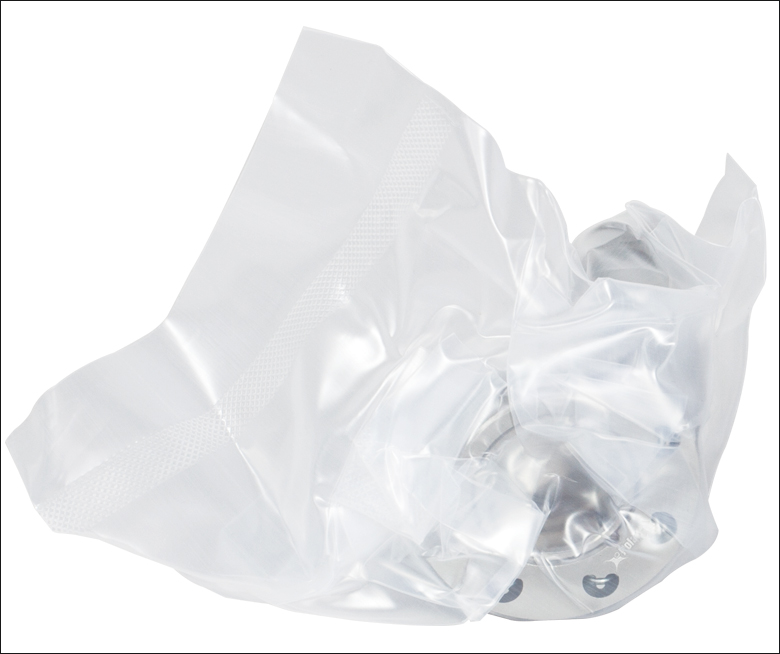
Figure 4.2 All PolarisKA mounts are shipped inside two vacuum bag layers.
The sapphire contacts are bonded into place using a NASA-approved low outgassing procedure. In addition, DuPont LVP High-Vacuum (Krytox) Grease, an ultra-high vacuum compatible, low outgassing PTFE grease, is applied to the adjusters. These features provide high vacuum compatibility and low outgassing performance. When operating at pressures below 10-5 Torr, we highly recommend using an appropriate bake out procedure prior to installing the mount in order to minimize contamination caused by outgassing. Please note that the 8-32 and M4 cap screws included with the Polaris mounts are not rated for pressures below 10-5 Torr.
Cleanroom-Compatible Packaging
Each vacuum-compatible Polaris mount is packaged within two vacuum bag layers after assembly in a clean environment, as seen in Figure 4.2. The vacuum-tight fit of the bags stabilizes the mount, limiting translation of the front plate due to shocks during transportation. The tight fit also minimizes rubbing against the bag, preventing the introduction of bag material shavings that would contaminate the clean mount.
In the vacuum-sealing process, moisture-containing air is drawn out of the packaging. This eliminates unwanted reactions on the surface of the mount without the need for desiccant materials. The vacuum bags protect the mount from contamination by air or dust during transport and storage, and the double-vacuum bag configuration allows for a straightforward and effective cleanroom entry procedure. The outer bag can be removed outside of the cleanroom, allowing the contaminant-free inner bag to be placed into a clean container and transferred into the cleanroom while retaining the benefits of vacuum-bag packaging. Inside the cleanroom, the mount can be removed from the inner bag when ready for use.
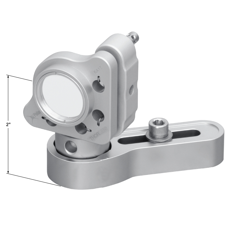
Click to Enlarge
Figure 5.1 These mounts can be mounted to a surface using a Ø1" Post and a clamping arm designed for Polaris mounts. Using a 1" long post, the optical axis is 2" above the table surface.
Through thermal changes and vibrations, Polaris®KA kinematic mirror mounts are designed to provide years of use. Below are some usage tips to ensure that the mount provides optimal performance.
Mounting Guidelines
When installing PolarisKA mounts, we recommend using Ø1" posts and a clamping arm designed for Polaris mounts. If not available, we recommend mounting to aluminum components.
Use a Wide Post
The performance of these mounts is optimized for use with our posts and clamping arms designed for Polaris mounts. These posts are made of stainless steel and provide two lines of contact with the mount, which help confine the bottom of the mount during variations in the surrounding temperature, thereby minimizing potential alignment issues.
Optic Mounting
Since an optic is prone to movement within its mounting bore, all optics should be mounted with the mount out of the setup to ensure accurate mounting that will minimize misalignment effects. We recommend using a TD24 torque wrench with an SPB1 spanner bit for SM1-threaded optic mounts, respectively. See the Specs tab for recommended torques. Over torquing the optic retaining rings can result in dramatic surface distortions.
Front Plate’s Position
The mounts sold on this page are designed to allow adjustments of up to 8°. To achieve the best performance, it is recommended that the front plate be kept as parallel as possible to the back plate. This ensures the highest stability of the adjustments.
Mount as Close to the Table’s Surface as Possible
To minimize the impact of vibrations and temperature changes, it is recommended that your setup has as low of a profile as possible. Using short posts will reduce the Y-axis translation caused by temperature variations and will minimize any movements caused by vibrations. The mount can also be secured directly to an optical table or breadboard using a 1/4"-20 to 8-32 thread adapter (Item # AE8E25E) or M6 x 1.0 to M4 x 0.7 thread adapter (Item # AE4M6M). By doing so, the instability introduced by a post will be eliminated. These mounts would perform best when mounted directly to an aluminum base plate.
Polish and Clean the Points of Contact
We highly recommend that the points of contact between the mount and the post, as well as the post and the table, are clean and free of scratches or defects. For best results, we recommend using a polishing stone to clean the table’s surface and an LF1P polishing pad for the top and bottom of the post as well as the bottom of the mount.
Use Polaris-Specific Adjustment Tools
The SA1 Adjustment Tool features a precision fit tip that is designed for the 0.07" side-hole adjusters used in the KA1TA and KA1T mounts. Additionally, its handle includes a 5/64" (2.0 mm) hex that is compatible with the hex on the end of each adjuster screw. For KA1TA and KA1T mounts that are exposed to shock and vibration, Thorlabs offers the LN25100H 1/4"-100 Lock Nut. In situations where frequent adjustment is required, the LN25100H lock nut can be hand-tightened with a torque of 4 to 8 oz-in (0.03 to 0.06 N•m). If long-term stability is required, the TW13 Torque Wrench can be used to tighten the lock nuts with
32 oz-in of torque.
Not Recommended
We do not recommend taking the adjusters out of the back plate, as it can contaminate the threading. This can reduce the fine adjustment performance significantly. Also, do not pull the front plate away as it might stretch the springs beyond their operating range or crack the sapphire seats. Finally, do not over tighten the retaining screws that secure the flat spring that holds the optic in place; only slight force is required to secure the optic in place.
| SM05 Threading: Ø1/2" Lens Tubes, 16 mm Cage Systems | |||
|---|---|---|---|
| External Thread, 0.535"-40.0 UNS-2A | Internal Thread, 0.535"-40.0 UNS-2B | ||
| Max Major Diameter | 0.5340" | Min Major Diameter | 0.5350" |
| Min Major Diameter | 0.5289" | Min Pitch Diameter | 0.5188" |
| Max Pitch Diameter | 0.5178" | Max Pitch Diameter | 0.5230" |
| Min Pitch Diameter | 0.5146" | Min Minor Diameter (and 83.3% of Thread) | 0.508" |
| Max Minor Diameter | 0.5069" | Max Minor Diameter (and 64.9% of Thread) | 0.514" |
| RMS Threading: Objective, Scan, and Tube Lenses | |||
|---|---|---|---|
| External Thread, 0.800"-36.0 UNS-2A | Internal Thread, 0.800"-36.0 UNS-2B | ||
| Max Major Diameter | 0.7989" | Min Major Diameter | 0.8000" |
| Min Major Diameter | 0.7934" | Min Pitch Diameter | 0.7820" |
| Max Pitch Diameter | 0.7809" | Max Pitch Diameter | 0.7866" |
| Min Pitch Diameter | 0.7774" | Min Minor Diameter (and 83.3% of Thread) | 0.770" |
| Max Minor Diameter | 0.7688" | Max Minor Diameter (and 64.9% of Thread) | 0.777" |
| C-Mount Threading: Machine Vision Lenses, CCD/CMOS Cameras | |||
|---|---|---|---|
| External Thread, 1.000"-32.0 UN-2A | Internal Thread, 1.000"-32.0 UN-2B | ||
| Max Major Diameter | 0.9989" | Min Major Diameter | 1.0000" |
| Min Major Diameter | 0.9929" | Min Pitch Diameter | 0.9797" |
| Max Pitch Diameter | 0.9786" | Max Pitch Diameter | 0.9846" |
| Min Pitch Diameter | 0.9748" | Min Minor Diameter (and 83.3% of Thread) | 0.966" |
| Max Minor Diameter | 0.9651" | Max Minor Diameter (and 64.9% of Thread) | 0.974" |
| SM1 Threading: Ø1" Lens Tubes, 30 mm Cage Systems | |||
|---|---|---|---|
| External Thread, 1.035"-40.0 UNS-2A | Internal Thread, 1.035"-40.0 UNS-2B | ||
| Max Major Diameter | 1.0339" | Min Major Diameter | 1.0350" |
| Min Major Diameter | 1.0288" | Min Pitch Diameter | 1.0188" |
| Max Pitch Diameter | 1.0177" | Max Pitch Diameter | 1.0234" |
| Min Pitch Diameter | 1.0142" | Min Minor Diameter (and 83.3% of Thread) | 1.008" |
| Max Minor Diameter | 1.0068" | Max Minor Diameter (and 64.9% of Thread) | 1.014" |
| SM30 Threading: Ø30 mm Lens Tubes | |||
|---|---|---|---|
| External Thread, M30.5 x 0.5 – 6H/6g | Internal Thread, M30.5 x 0.5 – 6H/6g | ||
| Max Major Diameter | 30.480 mm | Min Major Diameter | 30.500 mm |
| Min Major Diameter | 30.371 mm | Min Pitch Diameter | 30.175 mm |
| Max Pitch Diameter | 30.155 mm | Max Pitch Diameter | 30.302 mm |
| Min Pitch Diameter | 30.059 mm | Min Minor Diameter (and 83.3% of Thread) | 29.959 mm |
| Max Minor Diameter | 29.938 mm | Max Minor Diameter (and 64.9% of Thread) | 30.094 mm |
| SM1.5 Threading: Ø1.5" Lens Tubes | |||
|---|---|---|---|
| External Thread, 1.535"-40 UNS-2A | Internal Thread, 1.535"-40 UNS-2B | ||
| Max Major Diameter | 1.5339" | Min Major Diameter | 1.535" |
| Min Major Diameter | 1.5288" | Min Pitch Diameter | 1.5188" |
| Max Pitch Diameter | 1.5177" | Max Pitch Diameter | 1.5236" |
| Min Pitch Diameter | 1.5140" | Min Minor Diameter (and 83.3% of Thread) | 1.508" |
| Max Minor Diameter | 1.5068" | Max Minor Diameter (and 64.9% of Thread) | 1.514" |
| SM2 Threading: Ø2" Lens Tubes, 60 mm Cage Systems | |||
|---|---|---|---|
| External Thread, 2.035"-40.0 UNS-2A | Internal Thread, 2.035"-40.0 UNS-2B | ||
| Max Major Diameter | 2.0338" | Min Major Diameter | 2.0350" |
| Min Major Diameter | 2.0287" | Min Pitch Diameter | 2.0188" |
| Max Pitch Diameter | 2.0176" | Max Pitch Diameter | 2.0239" |
| Min Pitch Diameter | 2.0137" | Min Minor Diameter (and 83.3% of Thread) | 2.008" |
| Max Minor Diameter | 2.0067" | Max Minor Diameter (and 64.9% of Thread) | 2.014" |
| SM3 Threading: Ø3" Lens Tubes | |||
|---|---|---|---|
| External Thread, 3.035"-40.0 UNS-2A | Internal Thread, 3.035"-40.0 UNS-2B | ||
| Max Major Diameter | 3.0337" | Min Major Diameter | 3.0350" |
| Min Major Diameter | 3.0286" | Min Pitch Diameter | 3.0188" |
| Max Pitch Diameter | 3.0175" | Max Pitch Diameter | 3.0242" |
| Min Pitch Diameter | 3.0133" | Min Minor Diameter (and 83.3% of Thread) | 3.008" |
| Max Minor Diameter | 3.0066" | Max Minor Diameter (and 64.9% of Thread) | 3.014" |
| SM4 Threading: Ø4" Lens Tubes | |||
|---|---|---|---|
| External Thread, 4.035"-40 UNS-2A | Internal Thread, 4.035"-40.0 UNS-2B | ||
| Max Major Diameter | 4.0337" | Min Major Diameter | 4.0350" |
| Min Major Diameter | 4.0286" | Min Pitch Diameter | 4.0188" |
| Max Pitch Diameter | 4.0175" | Max Pitch Diameter | 4.0245" |
| Min Pitch Diameter | 4.0131" | Min Minor Diameter (and 83.3% of Thread) | 4.008" |
| Max Minor Diameter | 4.0066" | Max Minor Diameter (and 64.9% of Thread) | 4.014" |
| Posted Comments: | |
| No Comments Posted |
光学素子用キネマティックミラーマウント、3アジャスタ型")
 ズーム
ズーム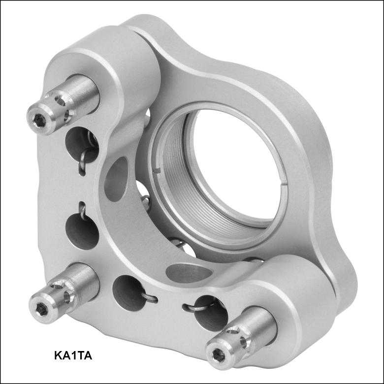
Click to Enlarge
Figure G1.1 マウントKA1TAには、サイドホール付きアジャスタが3つ付いています。
- 3アジャスタ、六角レンチ操作型、サイドホール付き
- Ø25.4 mm(Ø1インチ)光学素子用
- 本体と整合した1/4"-100ネジ付きアジャスタ
- 角度調整範囲:±4°(公称値)
- 分解能:約7.7 mrad/回転
- 温度サイクル試験後の変化量は4 µrad以下(詳細は「試験データ」タブ参照)
- 汚染を低減するバネの設計(特許申請中)
Ø25.4 mm(Ø1インチ)光学素子用の3アジャスタ付きPolarisKAシリーズキネマティックミラーマウントKA1TAは、高分解能での調整を容易に行うことができるだけでなく、産業用として必要なアライメントの長期安定性も得られるように設計されています。光学素子取付け穴にはSM1内ネジが付いており、これに厚さ8.6 mm以下のØ25.4 mm(Ø1インチ)光学素子またはSM1ネジ付きコンポーネントを取り付けることができます。 アジャスタが3つあることで、あおり調整(チップ&チルト)に加えて、Z軸(光軸)方向の移動調整も可能です。 このほか、2アジャスタ型の製品もご用意しております(下記参照)。
1/4"-100ネジ付きアジャスタにはØ1.8 mmの貫通穴が3つあり、当社の精密サイドホール調整ツールSA1(下記参照)、または1.5 mmのボール(六角)ドライバや六角レンチを使用して側面から操作することができます。各アジャスタには2.0 mm六角穴があり、SA1の端に付いている六角レンチやつまみネジ型六角レンチHKTS-5/64(下記参照)、あるいは一般的な2.0 mm六角レンチでも操作できます。このマウントのアジャスタは調整ノブF25USK3でも調整することができ、また止めナットLN25100Hでロックすることも可能です(いずれも別売り、下記参照)。アジャスタをたびたび調整しなければならない場合には、止めナットはおよそ0.03~0.06 N·mのトルクで軽く締めるだけで十分です。長期安定性を必要とする場合には、締め付けトルクとして0.23 N•mを推奨していますが、このトルクは当社のプリセット型トルクレンチTW13(下記参照)をご使用いただくと得ることができます。
取り付けた光学素子は、2つの白アルマイト加工アルミニウム製の固定リング(付属しています)を用いて保持します。この固定リング(型番SM1KRR)は、別途、追加購入いただくこともできます。ポストへの取付けには、互いに90°の位置に配置された2つのM4用ザグリ穴のどちらかを用います。当社では、このマウントの取付け用ポストとして、Polarisミラーマウント用のステンレススチール製Ø25 mmポストをお勧めしています。
注:これらのマウントはØ25.4 mm(Ø1インチ)光学素子用に設計されており、ミリ規格のØ25 mmミラーには対応しておりませんのでご注意ください。
光学素子用キネマティックミラーマウント、2アジャスタ型")
 ズーム
ズーム
Click to Enlarge
Figure G2.1 マウントKA1Tにはサイドホール付きのアジャスタが2つ付いており、KA1TBには六角レンチで調整可能な低頭アジャスタが2つ付いています。
- 2つのサイドホール付きアジャスタ、または六角レンチで調整可能な2つの低頭アジャスタ
- Ø25.4 mm(Ø1インチ)光学素子用
- 本体と整合した1/4"-100ネジ付きアジャスタ
- 角度調整範囲:±4°(公称値)
- 分解能:約7.7 mrad/回転
- 温度サイクル試験後の変化量は4 µrad以下(詳細は「試験データ」タブ参照)
- 汚染を低減するバネの設計(特許申請中)
2アジャスタ型のSM1ネジ付きØ25.4 mm(Ø1インチ)光学素子用PolarisKAキネマティックミラーマウントKA1TおよびKA1TBは、上記の標準的な3アジャスタ付きの製品と似ていますが、3つ目のアジャスタが硬化鋼製のボールに置き換えられています。2アジャスタの場合は動きの自由度が制限されるため、マウントの安定性が向上します。そのため、このようなマウントは、過酷な環境で信頼性の高い動作が求められる、組み込み(OEM)用途に適しています。 光学素子取付け穴にはSM1内ネジが付いており、これに厚さ8.6 mm以下のØ25.4 mm(Ø1インチ)光学素子またはSM1ネジ付きコンポーネントを取り付けることができます。 各アジャスタには2 mm六角穴があり、SA1の端についている六角レンチやつまみネジ型六角レンチHKTS-5/64(下記参照)、あるいは一般的な2 mm六角レンチでも操作できます。
マウントKA1TのアジャスタにはØ1.8 mmの貫通穴があるため、当社の精密サイドホール調整ツールSA1(下記参照)、または1.5 mmのボール(六角)ドライバや六角レンチを使用して側面から操作することができます。このマウントのアジャスタは調整ノブF25USK3でも調整することができ、また止めナットLN25100Hでロックすることも可能です(いずれも別売り、下記参照)。アジャスタをたびたび調整しなければならない場合には、止めナットはおよそ0.03~0.06 N·mのトルクで軽く締めるだけで十分です。長期安定性を必要とする場合には、締め付けトルクとして0.23 N•mを推奨していますが、このトルクは当社のプリセット型トルクレンチTW13(下記参照)をご使用いただくと得ることができます。
マウントKA1TBには、狭い空間にも対応できるように、KA1Tのアジャスタよりも8.1 mm短い低頭六角アジャスタが付いています。アジャスタが短いため、マウントKA1TBには止めナットLN19100Hや調整ノブF25USK3はご使用いただけません。
取り付けた光学素子は、2つの白アルマイト加工アルミニウム製の固定リング(付属しています)を用いて保持します。この固定リング(型番SM1KRR)は、別途、追加購入いただくこともできます。ポストへの取付けには、互いに90°の位置に配置された2つのM4用ザグリ穴のどちらかを用います。当社では、これらのマウントの取付け用ポストとして、Polarisミラーマウント用のステンレススチール製Ø25 mmポストをお勧めしています。
注:これらのマウントはØ25.4 mm(Ø1インチ)光学素子用に設計されており、ミリ規格のØ25 mmミラーには対応しておりませんのでご注意ください。

 ズーム
ズーム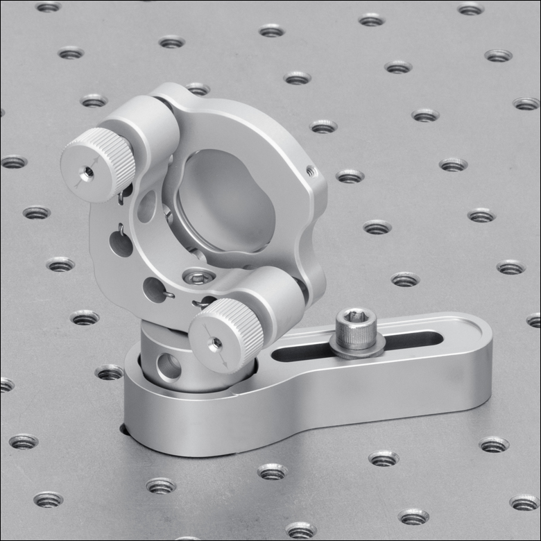
Click to Enlarge
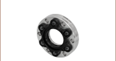
Figure 801A アルミニウム製アジャスターネジF25USK3の取り付けられたサイドホールド型マウントKA1
- 1/4"-100アジャスターネジの調整用
- アジャスターネジに直接取付け可能
- 1個単位で販売
アルミニウム製の着脱可能ノブF25USK3を用いると、1/4"-100アジャスターネジを手で回すことができるようになります。PolarisKA マウントと同じアルミニウム合金製で、製造方法も同じです(詳細は「仕様」タブをご覧ください)。ノブはアジャスターネジに直接ねじ込むことができます。ノブの取付け後も2.5 mmの貫通穴からアジャスターネジの2 mm六角ソケットにアクセスできるため、六角レンチ等での操作は可能です。なお、PolarisKAシリーズマウントにこのノブを取り付けると、アジャスターネジのサイドホールがブロックされますのでご注意ください。なお、これらのノブは低頭アジャスタの付いたPolarisマウントには取り付けられませんのでご注意ください。
つまみネジ型六角レンチ")
 ズーム
ズーム
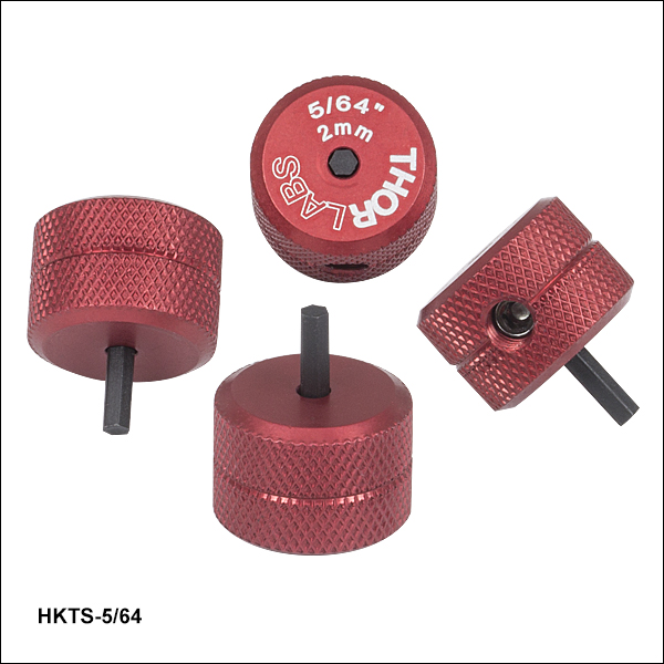
- 2 mm(5/64インチ)の六角レンチを使用するアクチュエータの調整に便利
- 赤色アルマイト加工の調整ノブで六角レンチのサイズが刻印
- 六角チップは取り替え可能
- 1パック4個入り
この2 mm(5/64インチ)六角レンチ型の調整用つまみネジを使用することで、2 mm六角レンチで調整するアクチュエータ(またはノブを取り外した標準タイプのアクチュエータ)が迅速に調整できます。 これは取り外し可能なノブであるため、調整の合間にネジの六角穴に取り付けたままにしておくことができて便利です(Figure 206A参照)。 #8-32止めネジ(2 mm六角)が取り替え可能の六角形のビットを固定します。この取り替え可能なビットは、一方の先端がつぶれてしまっても、逆向きで再利用できます。 交換用の六角レンチ型ビットが必要な場合には、当社にお問い合わせください。
つまみネジ型六角レンチには、0.050~3/16インチと2 mm~5 mmのサイズの製品があります。

 ズーム
ズーム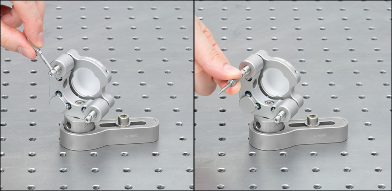
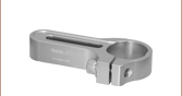
- Polarisアジャスタのサイドホールに精密にフィットするØ1.7 mmの先端
- ハンドル部分に2.0 mm六角レンチ
- 化学洗浄済みで、磁性のあるステンレススチール製
サイドホール調整ツールには、Polarisマウントのサイドホールアジャスタに精密にフィットするように設計されたØ1.7 mmの先端があります。ハンドルには2.0 mm六角レンチがついており、SA1を小さなつまみのように使用することができます。また中央のナットには6.0 mmレンチが取付け可能なため、長めのレバーアームを構成することもできます。精密な先端は調整時のバックラッシュが小さく、また深さストッパにより調整中のツールをサイドホール内にしっかり固定しておくことができます。Ø25 mmよりも大きいミラーマウントに対しては、ツールの長さが41.2 mmであるため、マウント背面にあるほかのアジャスタと干渉せずにアクチュエータを360°調整できます。
SA1は化学洗浄と硬化処理を施されたステンレススチール製で、耐久性があるうえにクリーンな環境にも対応します。磁性があるため、スペースのない、あるいは振動に敏感なセットアップでは磁石を使用してツールを回収することができます。

 ズーム
ズーム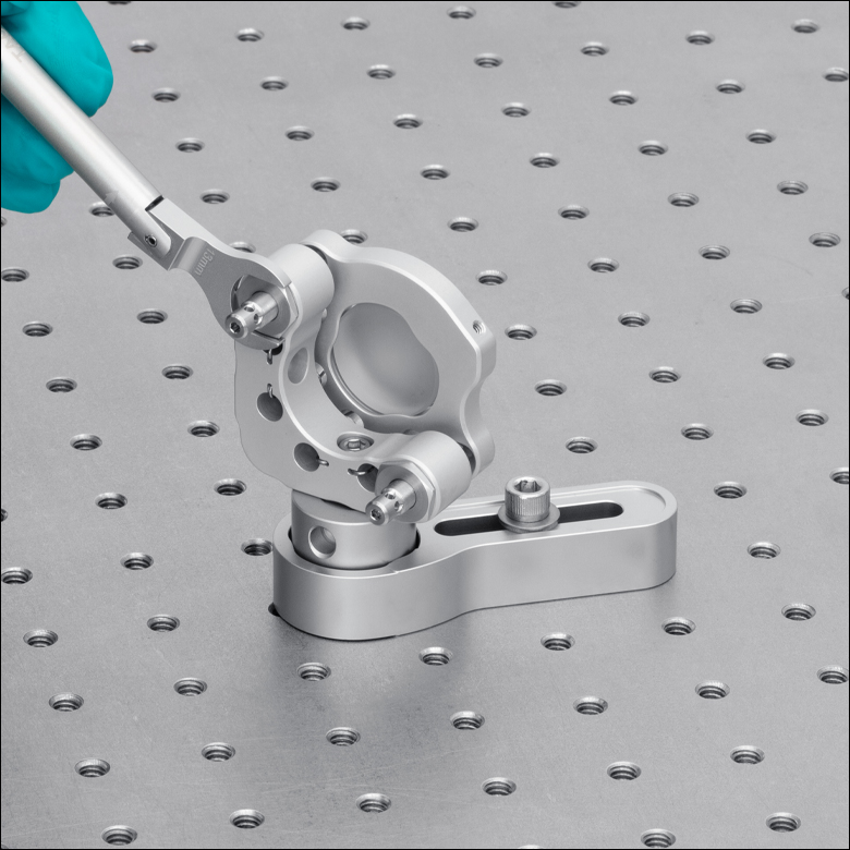
Click to Enlarge
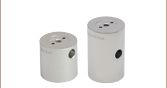
Figure 800B トルクレンチTW13を使用して、ミラーマウントKA1のアジャスタを止めナットLN25100Hで固定

Click to Enlarge
Figure 800A トルクレンチTW13には型番とプリセットされたトルク値が刻印されています。
- 1/4"-100アルミニウム製止めナットLN25100Hでアジャスタの長期安定性を確保
- 長期的に固定するのに適したトルクレンチTW13
- プリセット値:0.23 N•m
- 適切なトルクを確実に負荷できるブレークオーバー(Break-Over)型
止めナットLN25100Hは、1/4"-100アジャスタ付きのPolarisKAシリーズマウント用に設計されています(低頭アジャスタの付いたKA1Bと KA1TBを除く)。この止めナットは、アジャスタに対して長期的な安定性や、衝撃や振動にさらされるセットアップに使用したときの安定性などが求められるアプリケーション用として設計されています。PolarisKAシリーズマウントと同じアルミニウム合金製で、製造方法も同じです(詳細は「仕様」タブをご覧ください)。
アジャスタをたびたび調整しなければならない場合には、止めナットは手でおよそ0.03~0.06 N·mのトルクで軽く締めるだけで十分です。長期的な安定性が求められる場合には、トルクレンチTW13(下記参照)を使用して各止めナットを0.23 N•mのトルクで締め付けることができます。止めナット取付け時のクロススレッド(斜めにねじ込む状態)を防ぐために、まず止めナットをアジャスタに当ててネジが緩む方向に回し、かすかなネジの段差の感触でネジが整合したことを確認してからネジを締めるようにしてください。
プリセット型トルクレンチ
このトルクレンチには、Polarisマウントのアジャスタを、13 mm止めナットで長期的に固定するうえで適切なトルク値がプリセットされています。プリセットされたトルク値に達すると、Figure 800Bのようにピボットジョイントが折れ曲がるように設計されています。力を抜くと、レンチの六角ヘッドは元の位置に戻ります。この設計により、止めナットに設定値以上のトルクが加わるのを防止しています。指標として刻印されている線は、定められたトルクをかけるためにレンチを回転させる角度を示しています。この線を越えてハンドルを回転させると、止めナットを締め付けすぎていることになります。レンチには、使用時に識別しやすいように、プリセットのトルク値、トルクをかける方向、レンチサイズ、および型番が刻印されています。
このレンチは、クリーンルームや真空チャンバ内でも使用可能です。Carpenter AAA不動態化処理による化学洗浄を行い、表面から硫黄、鉄、汚染物質などを除去しています。不動態化処理の後は、クリーンな(汚染されていない)環境下で組み立て、2重の真空バッグに入れてクリーンルームに搬入するまでの間に汚染されないようにしています。また、レンチはビードブラスト加工されており、レーザが使用されているセットアップで作業するときに、反射光が最小限に抑えられるようになっています。
なお、このレンチはアジャスタを高頻度で調整するためのものではありません。そのような用途で必要とされるトルク値は、通常0.03~0.06 N·mです。

 ズーム
ズーム- アジャスタの長期安定性を保持
- Polarisマウントに対応(一部使用できない製品あり)
- Ø8.4 mm x 厚さ1.9 mmの薄型
- スパナレンチPOLARIS-T2を使用して回転軸に沿った締め付けが可能
こちらのロック用カラーは、ピエゾ駆動のマウントや低頭アジャスタ付きのマウント(型番POLARIS-K1E3、POLARIS-K1E2)を除く、1/4"-100アジャスタが付いたPolarisマウントに対応します。アジャスタの長期安定性、または衝撃や振動にさらされる用途向けに設計されているこちらのロック用カラーには、Polarisマウントと同様、あらかじめ高真空対応のアウトガスの少ないPTFEグリースが塗布されており、またアジャスタとの適合性が試験されています。
スパナレンチPOLARIS-T2は、ロック用カラーPOLARIS-LNS1の固定用に特化して設計されています。ダブルスパナヘッドにより完全にかみ合い、またロック用カラーの調整はアジャスタと同一線上で行える設計です。スパナレンチの中心の貫通穴から2 mmボール(六角)ドライバが通るので、ロック用カラーを調整中にアジャスタを位置固定することができます。
アジャスタをたびたび調整しなければならない場合、ロック用カラーはおよそ0.03~0.06 N·mのトルクで軽く締め付けるだけで十分です。長期安定性を必要とする場合には、締め付けトルクとして0.23 N·mを推奨していますが、このトルクは当社のプリセット型トルクレンチTW13(下記参照)とスパナレンチPOLARIS-T2を合わせてご使用いただくと得ることができます。ロック用カラー締付け時のクロススレッド(斜めにねじ込む状態)を防ぐには、カラーをアジャスタの反対側に置き、カラーがアジャスタのネジにはまるまで緩める方向に回し、その後、アジャスタにねじ込んでください。