 Products Home / 自動(電動)ステージ / 電動回転ステージ・マウント / Motorized Tilt and Rotation Stage with Integrated Controller
Motorized Tilt and Rotation Stage with Integrated Controller
- ±3° Tilt and 360° Continuous Rotation
- Bidirectional Accuracy at ±0.05°
- Integrated DC Servo Motors and Controller
MTRS
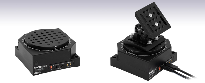
Motorized Tilt and Rotation Stage
AP180 Articulating Platform Mounted on MTRS Stage


Please Wait
| Key Specificationsa | ||
|---|---|---|
| Stage Specifications | Tilt | Rotation |
| Travel | ±3° | 360° (Continuous) |
| Maximum Velocity | 0.5 °/s | 1.5 °/s |
| Maximum Acceleration | 0.5 °/s2 | 1.5 °/s2 |
| Bidirectional Repeatability | 0.05° | ±0.05° |
| Min Incremental Movement | ±0.005° | ±0.005° |
| Bidirectional Accuracy | ±0.05° | ±0.05° |
| Horizontal Load Capacity | 5.0 kg (11.02 lbs) | |
| Vertical Load Capacity | 2.0 kg (4.41 lbs) | |
Click to Enlarge
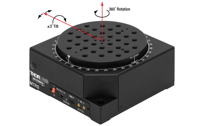
Figure 1.1 Rotation and Tilt Motion Illustration
Click for Details
Figure 1.3 MTRS/M Mounting Features
Click for Details
Figure 1.2 MTRS Mounting Features
Features
- ±3° Tilt and 360° Continuous Rotation
- 5 kg Horizontal Load Capacity (Approximate)
- 5 V TTL Input and Output Trigger Ports
- USB-C Connectivity for Plug and Play PC-Controlled Operation
- Multiple Units Can be Connected to PC for Multi-Axis Applications
The MTRS(/M) Motorized Tilt and Rotation Stage features two DC servo motors and an integrated DC controller. The controller includes a USB-C port that can be connected to a PC. Coupling this with the user-friendly Kinesis software allows plug and play operation, with advanced custom motion control applications and sequences also possible using the extensive programming environment supplied. This programming library is compatible with many development tools such as LabVIEW, Visual Basic, Visual C++, C++ Builder, LabWindows/CVI, MATLAB, and Delphi.
With a 115 mm x 115 mm footprint and an array of tapped holes (Figures 1.2 and 1.3), the MTRS(/M) stage is compatible with Thorlabs' ORIC® Piezo Inertia Rotation and Translation (5 mm and 20 mm) Stages, the KVS30 Motorized Vertical Translation Stage, or the M30XY Motorized XY Translation Stage, as well as general optomechanical components. By combining stages, up to 5-axis adjustment can be achieved. To change the nominal starting angle from 0°, adapters such as the AP30 angled mounting plate or the AP180 adjustable angle mounting plate can be secured to the platform. For applications that might require long linear travel + rotation and tilt control, the MTRS(/M) can also be mounted on the DDS300(/M) or DDS600(/M) direct drive stages, among others.
Engravings at 1° intervals provide a visual reference for the rotation and tilt of the stage. There is also an engraved line on the side of the moving platform to mark the axis about which the platform rotates when tilt adjustments are made.
With both rotation and tilt control (Figure 1.1), the MTRS(/M) stage is useful for applications such as imaging surface imperfections. The stage is also suitable for use with laser sources, fiber optics, and other multi-axis stages.
These stages are compatible with our Kinesis software package, which can be downloaded here. Please see the Kinesis Software tab for more information. Each stage includes a 79" (2 m) USB A to USB C cable for remote connections, two 72" (1.8 m) MMCX-to-BNC input and output trigger cables, and a 15 V, 2.4 A power supply. CA3439 MMCX to SMA cables are available separately.
| Item # | MTRS(/M) | |
|---|---|---|
| Stage Specifications | Tilt | Rotation |
| Travel | ±3° | 360° (Continuous) |
| Maximum Velocity | 0.5 °/s | 1.5 °/s |
| Maximum Acceleration | 0.5 °/s2 | 1.5 °/s2 |
| Bidirectional Repeatability | 0.05° | ±0.05° |
| Min Incremental Movement | ±0.005° | ±0.005° |
| Bidirectional Accuracy | ±0.05° | ±0.05° |
| Backlash | ±0.05° | ±0.05° |
| Axis Wobble | ±0.01° | |
| Load Capacity | ||
| Horizontal Load | 5.0 kg (11.02 lbs) | |
| Vertical Load | 2.0 kg (4.41 lbs) | |
| Input Power Requirements | ||
| Voltage | 15 V Regulated DC | |
| Current | 500 mA (Peak) | |
| General Data | ||
| Motor Type | 2 x DC Servo Motors | |
| Dimensions (W x D x H) at 0° of Tilt |
115 mm x 115 mm x 57.1 mm (4.53" x 4.53" x 2.25") |
|
| Mass (Without Cables) | 1.47 kg (3.24 lbs) | |
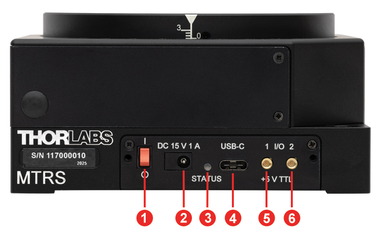
Click to Enlarge
Figure 3.1 MTRS Front Panel
| Table 3.2 MTRS(/M) Front Panel | |
|---|---|
| Callout | Description |
| 1 | Power Switch |
| 2 | Power Supply Connector |
| 3 | Status LED |
| 4 | USB Type-C Connectora |
| 5 | Output Connector, MMCX Socket, 5 V TTLb |
| 6 | Input Connector, MMCX Socket, 5 V TTLb |
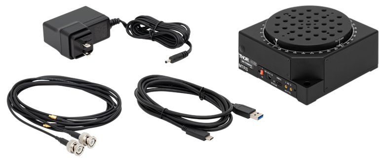
MTRS(/M) Shipping List
ソフトウェア
Kinesisバージョン1.14.58
このKinesisソフトウェアパッケージには、当社のKinesisシステムコントローラを制御するためのGUIが含まれています。
下記もご用意しております。
- ファームウェア更新ユーティリティ
- 通信プロトコル

Figure 58A KinesisソフトウェアのGUI画面
当社のKinesisソフトウェアパッケージを用いて、当社の様々なモーションコントローラを駆動することができます。このソフトウェアは小型で低出力のシングルチャンネルドライバ(K-Cube®など)から、高出力でマルチチャンネルのベンチトップ型ユニットやモジュール型の19インチラックナノポジショニングシステム(ラックシステムMMR60x)まで、当社Kinesisシリーズの様々なモーションコントローラの制御用にご使用いただけます。
Kinesisソフトウェアでは.NETコントロールを使用できるため、最新のC#、Visual Basic、LabVIEW™、あるいはその他の.NET対応言語を使用してカスタムプログラムを作成することができます。.NETフレームワークやAPIの使用を想定していないアプリケーションのために、ローレベルのDLLライブラリも含まれています。中央シーケンスマネージャ(Central Sequence Manager)は、当社のすべてのモーションコントロール用ハードウェアの統合と同期の機能をサポートしています。
この共通のソフトウェアプラットフォームにより、ユーザは単一のソフトウェアツールを習得するだけで、あらゆるモーションコントロールデバイスを1つのアプリケーション内で組み合わせて使用することができます。このように1軸システム用から多軸システム用までのあらゆるコントローラを組み合わせ、それら全てを1台のPCの統合されたソフトウェアインターフェイスから制御できます。
このソフトウェアパッケージには2つの使い方があります。1つはGUI(グラフィカルユーザーインターフェイス)ユーティリティを用いる方法で、コントローラの到着後すぐに直接的な操作と制御を行なうことができます。もう1つは一連のプログラミングインターフェイスを用いる方法で、ご希望の開発言語によりカスタム仕様の位置決めやアライメント用のプログラムを簡単に作成することができます。
Kinesisソフトウェアでは新しい.NETコントロールが使用でき、最新の最新のC#, Visual Basic, LabVIEW™、ほかの.NET対応言語を使用する開発者がカスタムにプログラムを作成することもできます。
C#
このプログラミング言語はマルチプログラミングパラダイムやマルチプログラミング言語が使用可能となるよう設計されているため、複雑な問題が簡単かつ効率的に解決できます。型付け、命令型、宣言型、関数型、ジェネリック、オブジェクト指向、そしてコンポーネント指向が含まれます。 この共通のソフトウェアプラットフォームにより、1セットのソフトウェアツールを習得するだけで、あらゆるKinesisコントローラを簡単に組み合わせることができます。このようにして1軸システムのコントローラから多軸システムのコントローラまで、様々なコントローラを組み合わせ、全てを1台のPCのソフトウェアインターフェイスから制御することが可能となりました。
Kinesisシステムソフトウェアを使用するには2つの手段があります。コントローラを直接つないで制御を行なう付属のGUI(グラフィカルユーザーインターフェイス)ユーティリティ、またはご希望の開発言語でカスタム仕様の位置決めやアライメントを簡単にプログラムできる一連のプログラミングインターフェイスです。
Kinesisモーションコントロールライブラリの構築の参考となる実行可能なプロジェクト機能拡張例については下のリンクをクリックしてください。なお、Quick Startのプロジェクト例の実行には別の統合開発環境(IDE)(Microsoft Visual Studioなど)が必要です。C#のプロジェクト例はKinesisソフトウェアパッケージに付属する.NETコントロールで実行可能です(詳細は「Kinesisソフトウェア」タブをご覧ください)。
 | Click Here for the Kinesis with C# Quick Start Guide Click Here for C# Example Projects Click Here for Quick Start Device Control Examples | |
LabVIEW
LabVIEWは、.Netコントロールを介してKinesisベースのコントローラとの通信に使用できます。LabVIEWでは、ツールとオブジェクトでフロントパネルとして知られるユーザーインターフェイスを構築した後、グラフィカル表記の関数を使ってコードを追加し、フロントパネルのオブジェクトを制御します。下記のLabVIEWチュートリアルでは.Netコントロールを使用してLabVIEW内Kinesis駆動デバイス用の制御GUIを作成するための情報をご提供しています。 LabVIEWでコントローラを制御する基本的な方法や、LabVIEW GUIを用いてデバイスを操作する前に行うべき設定の手順についても解説しています。
 | Click Here to View the LabVIEW Guide Click Here to View the Kinesis with LabVIEW Overview Page | |
| Posted Comments: | |
| No Comments Posted |
回転マウント&回転ステージのセレクションガイド
当社では手動式および電動式の回転マウントと回転ステージを豊富にご用意しております。回転マウントの内孔はØ12 mm~Ø12.7 mm(Ø1/2インチ)、Ø25 mm~Ø25.4 mm(Ø1インチ)、またはØ50 mm~Ø50.8 mm(Ø2インチ) の光学素子取付け用に設計されております*。また回転ステージには、様々な部品やシステムが取り付けられるようにタップ穴が配置されております。電動式は、DCサーボモータ、2相ステッピングモータ、あるいはElliptec™共振ピエゾモータにより駆動されます。いずれも360°の連続回転が可能です。
*下表のマウントは、Ø12.7 mm、Ø25.4 mm、Ø50.8 mmの光学素子に対して最適設計されています。Ø12.0 mm、Ø25.0 mm、Ø50.0 mmなどの少し小さい光学素子に対してもご使用いただけますが、光学素子の偏心が重要ではない用途でのご使用をお勧めします。
手動回転マウント
| Rotation Mounts for Ø1/2" Optics | |||||||
|---|---|---|---|---|---|---|---|
| Item # | MRM05(/M) | RSP05(/M) | CRM05 | PRM05(/M)a | SRM05 | KS05RS | CT104 |
| Click Photo to Enlarge | 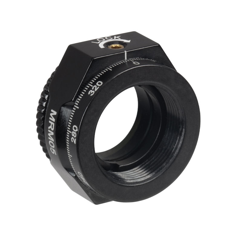 | 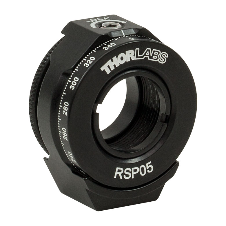 | 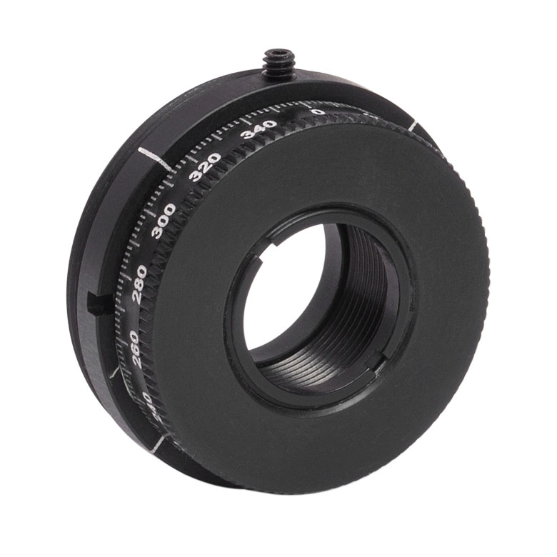 | 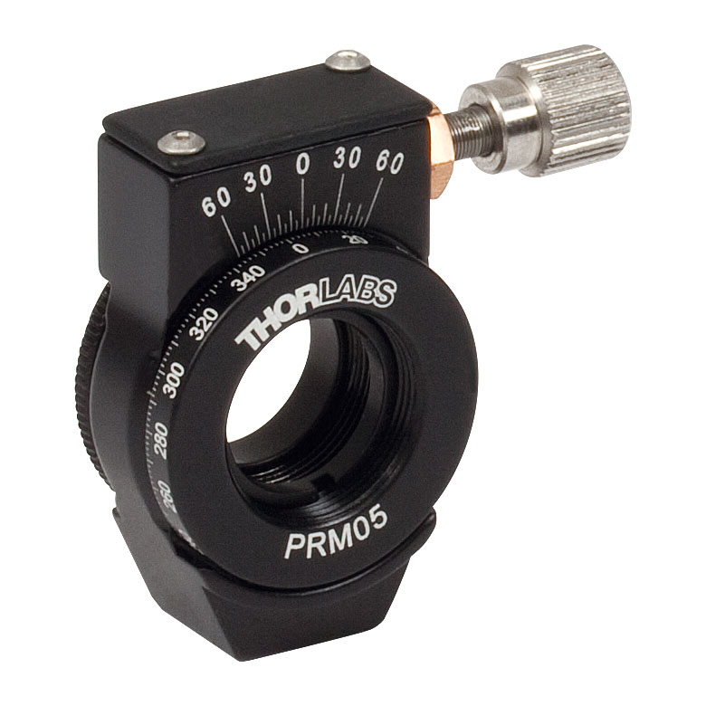 | 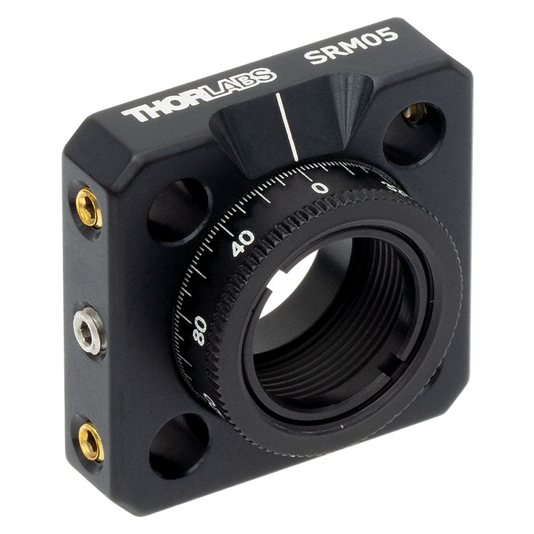 | 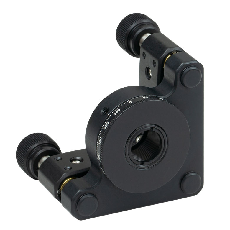 |  |
| Features | Mini Series | Standard | External SM1 (1.035"-40) Threads | Micrometer | 16 mm Cage-Compatible | ±4° Kinematic Tip/Tilt Adjustment Plus Rotation | Compatible with 30 mm Cage Translation Stages and 1/4" Translation Stagesb |
| Additional Details | |||||||
| Rotation Mounts for Ø1" Optics | ||||||||
|---|---|---|---|---|---|---|---|---|
| Item # | RSP1(/M) | LRM1 | RSP1D(/M) | DLM1(/M) | CLR1(/M) | RSP1X15(/M) | RSP1X225(/M) | PRM1(/M)a |
| Click Photo to Enlarge |  | 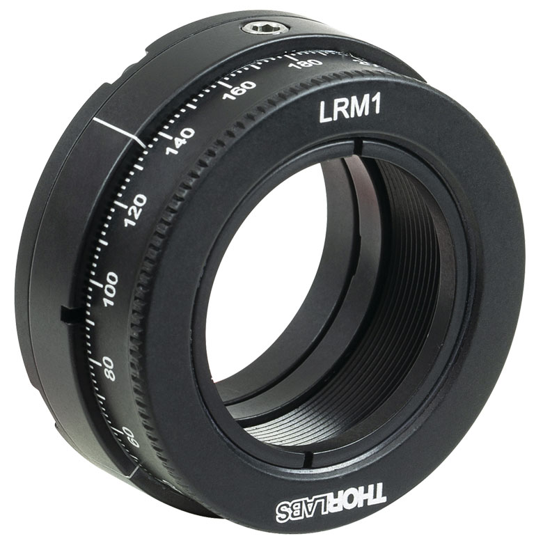 | 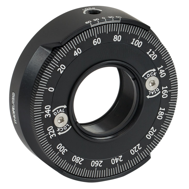 | 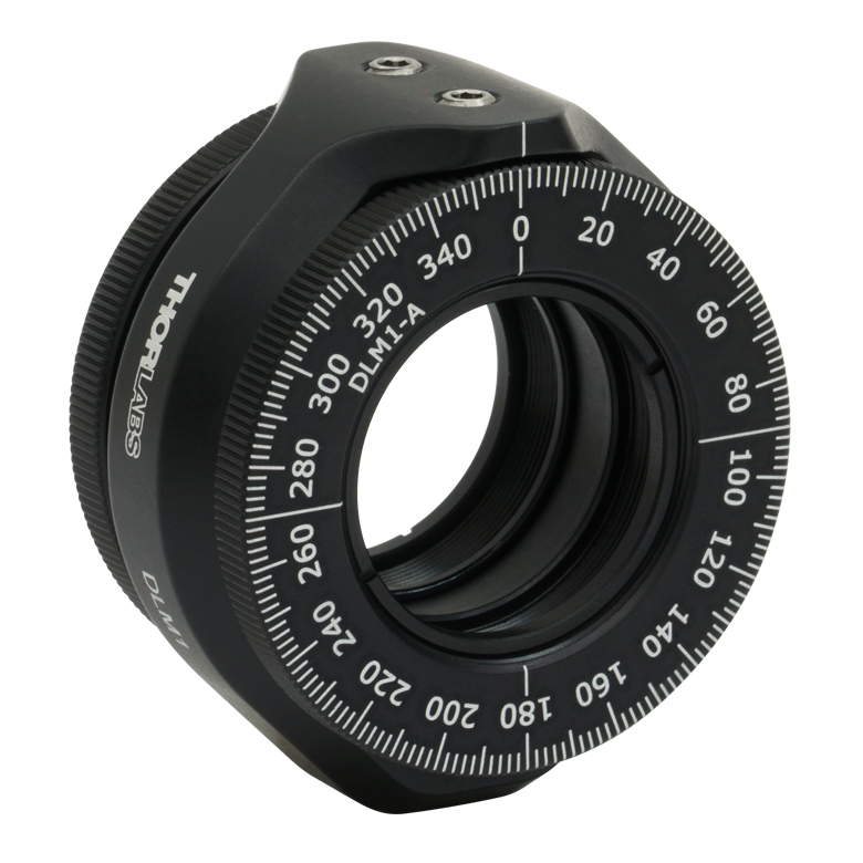 | 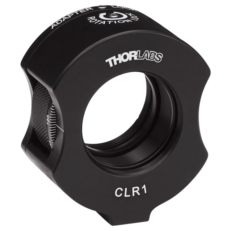 | 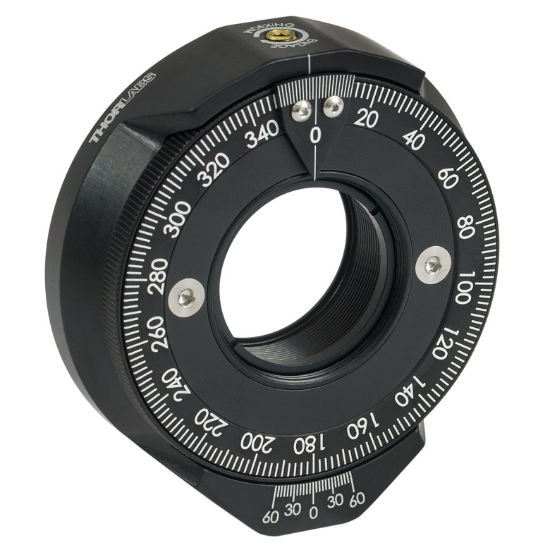 | | 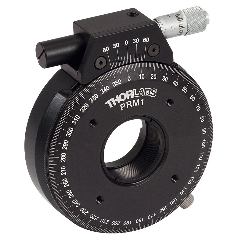 |
| Features | Standard | External SM1 (1.035"-40) Threads | Adjustable Zero | Two Independently Rotating Carriages | Rotates Optic Within Fixed Lens Tube System | Continuous 360° Rotation or 15° Increments | Continuous 360° Rotation or 22.5° Increments | Micrometer |
| Additional Details | ||||||||
| Rotation Mounts for Ø1" Optics | ||||||
|---|---|---|---|---|---|---|
| Item # | LM1-A & LM1-B(/M) | CRM1T(/M) | CRM1LT(/M) | CRM1PT(/M) | KS1RS | K6XS |
| Click Photo to Enlarge | 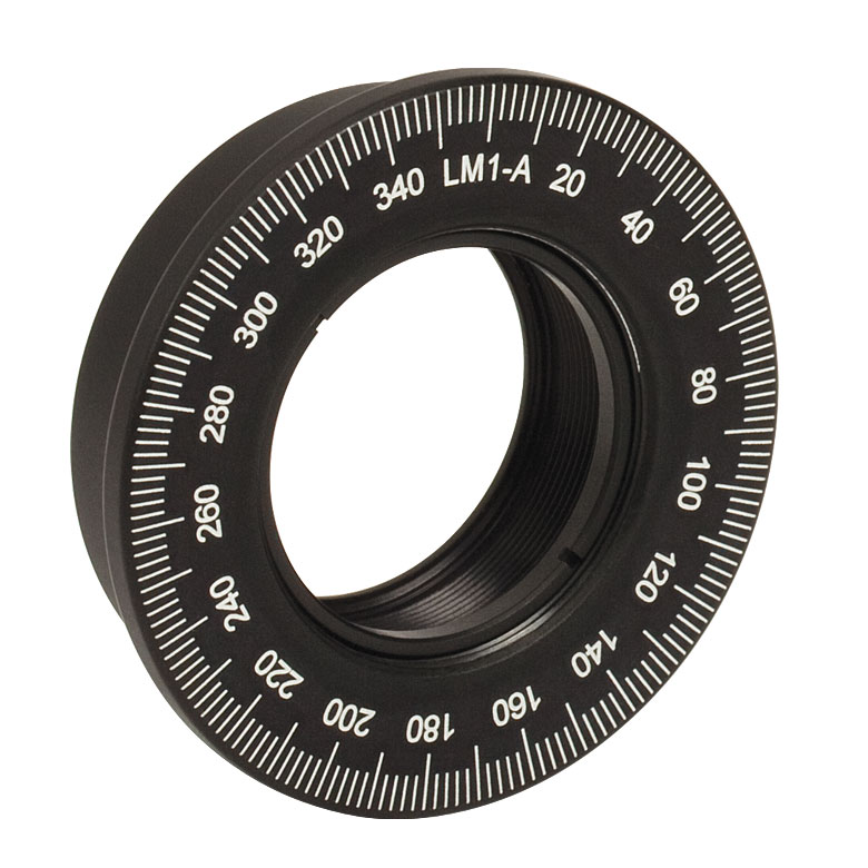 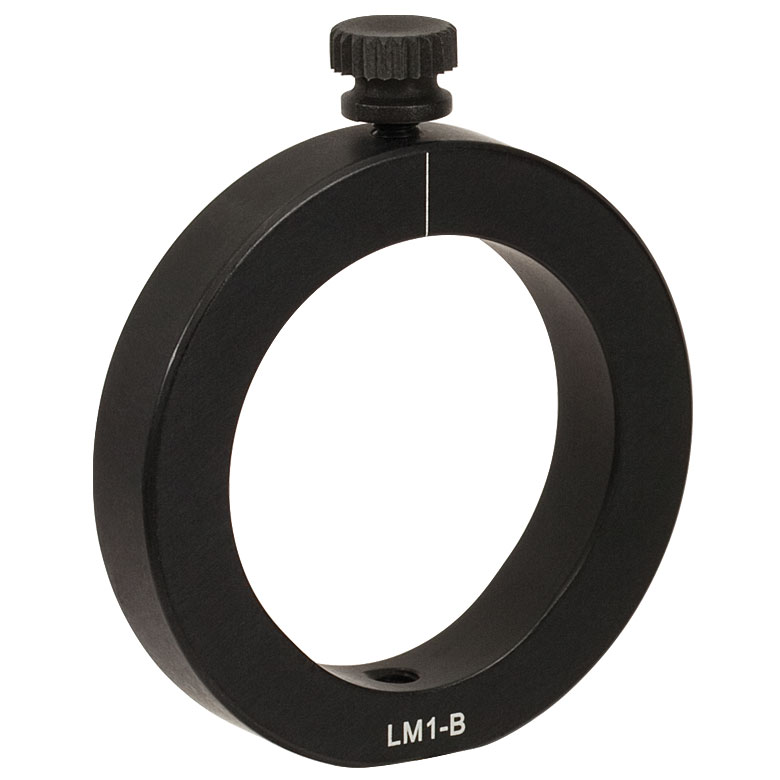 | 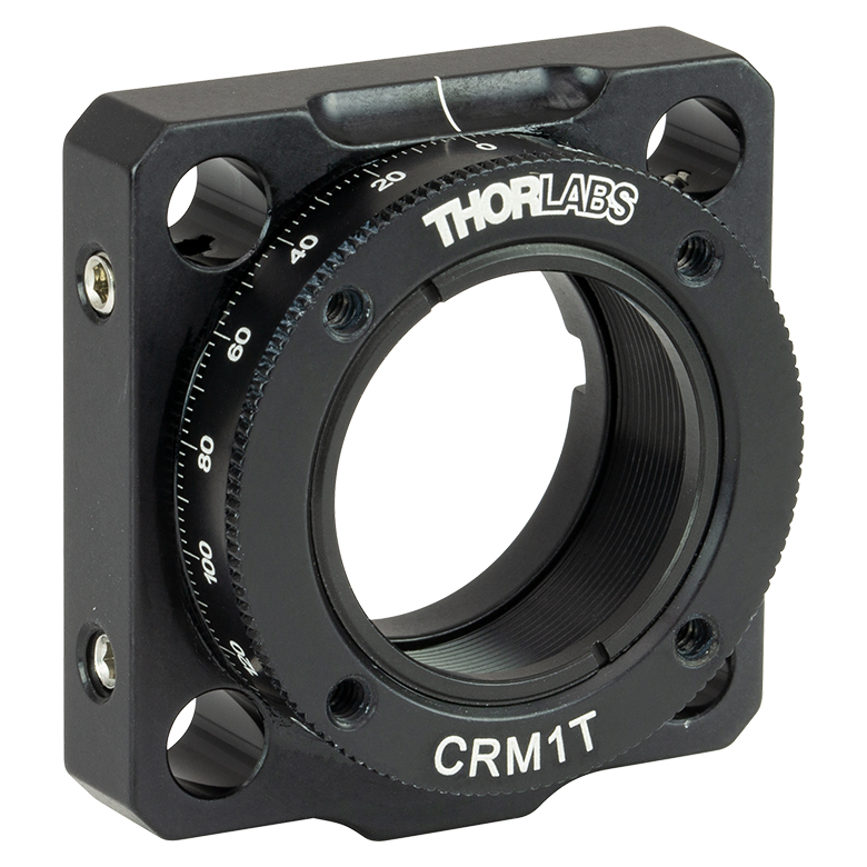 |  |  | 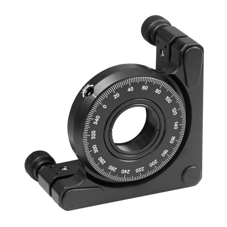 | 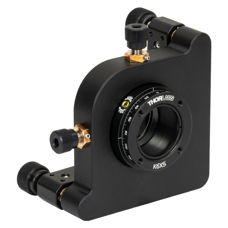 |
| Features | Optic Carriage Rotates Within Mounting Ring | 30 mm Cage-Compatiblea | 30 mm Cage-Compatible for Thick Opticsa | 30 mm Cage-Compatible with Micrometera | ±4° Kinematic Tip/Tilt Adjustment Plus Rotation | Six-Axis Kinematic Mounta |
| Additional Details | ||||||
| Rotation Mounts for Ø2" Optics | |||||||
|---|---|---|---|---|---|---|---|
| Item # | RSP2(/M) | RSP2D(/M) | PRM2(/M) | LM2-A & LM2-B(/M) | LCRM2A(/M) | KS2RS | K6X2 |
| Click Photo to Enlarge |  |  | 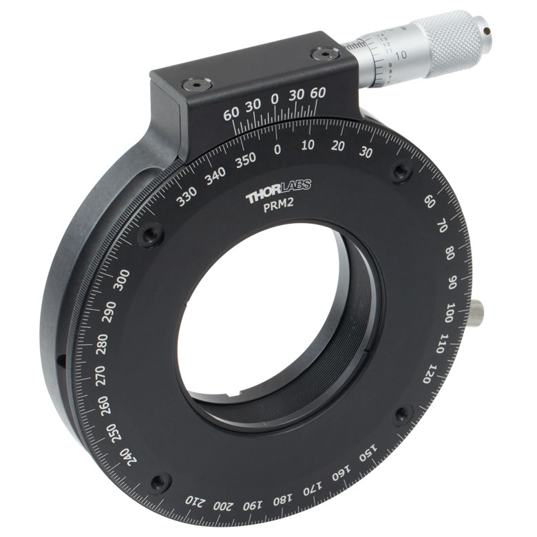 | 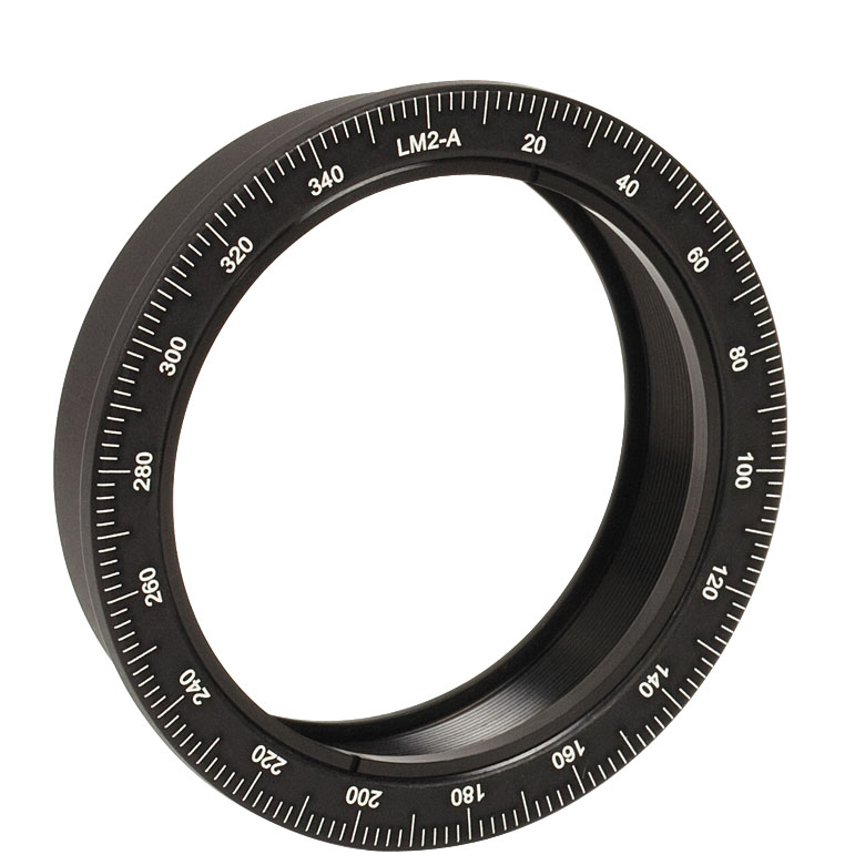 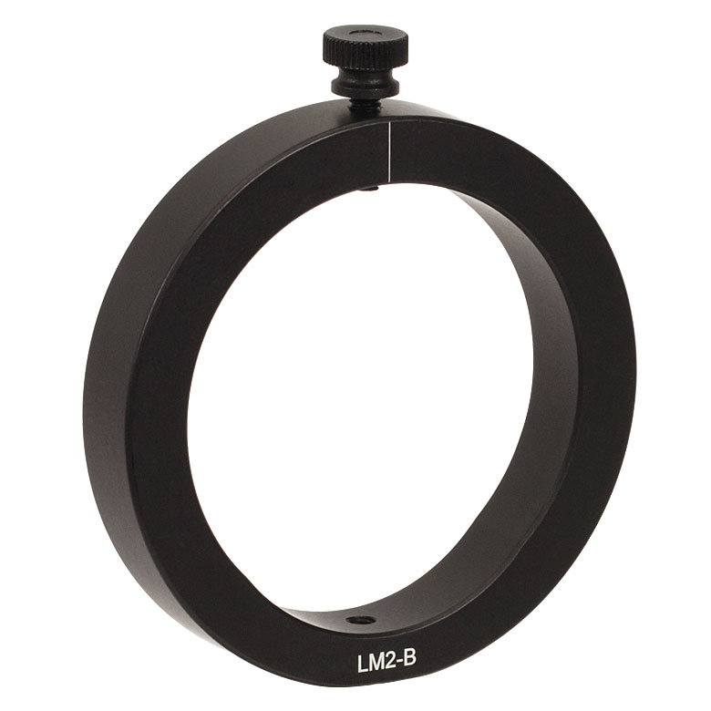 |  |  | 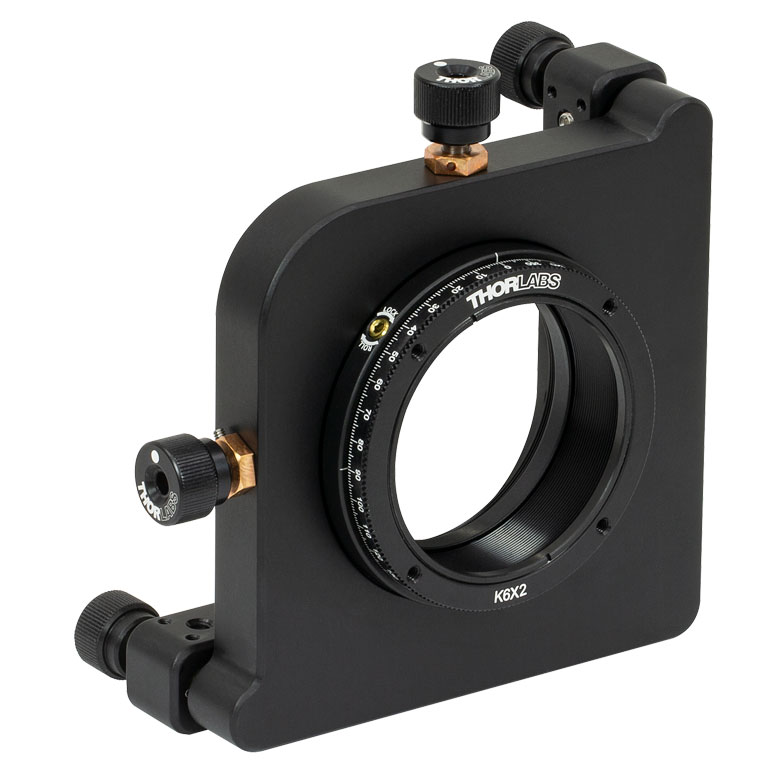 |
| Features | Standard | Adjustable Zero | Micrometer | Optic Carriage Rotates Within Mounting Ring | 60 mm Cage-Compatible | ±4° Kinematic Tip/Tilt Adjustment Plus Rotation | Six-Axis Kinematic Mount |
| Additional Details | |||||||
| Rotation Drive Mechanism and Adjustment Range | Manual, 360° Continuous | Coarse: Manual, 360° Continuous; Fine: ±7° Micrometer | Manual, 360° Continuous | ||||
| Optic Mounting | Internally SM2-Threaded Carriage | Internal SM2 Threads in LM2-A | Internally SM2-Threaded Carriage | ||||
| Maximum Accepted Optic Thickness | 0.51" (13 mm) | 0.54" (13.7 mm) | 0.48" (12.2 mm) | 0.46" (11.7 mm) | 0.52" (13.2 mm) | 0.47" (12 mm) | 0.53" (13.4 mm) |
| Post Mounting | 8-32 (M4) Tap | 8-32 (M4) Tap in LM2-B | 8-32 (M4) Tap | Four Counterbores for 8-32 (M4) Cap Screws | Six Counterbores for 8-32 (M4) Cap Screws | ||
| Cage System Compatibility | N/A | Four 4-40 (M3) Taps on Rotation Dial with 60 mm Spacing | N/A | Four Bores for Ø6 mm Cage Rods with 60 mm Spacing | N/A | N/A | |
手動回転ステージ
| Manual Rotation Stages | ||||||
|---|---|---|---|---|---|---|
| Item # | RP005(/M) | PR005(/M) | MSRP01(/M) | RP01(/M) | RP03(/M) | QRP02(/M) |
| Click Photo to Enlarge | 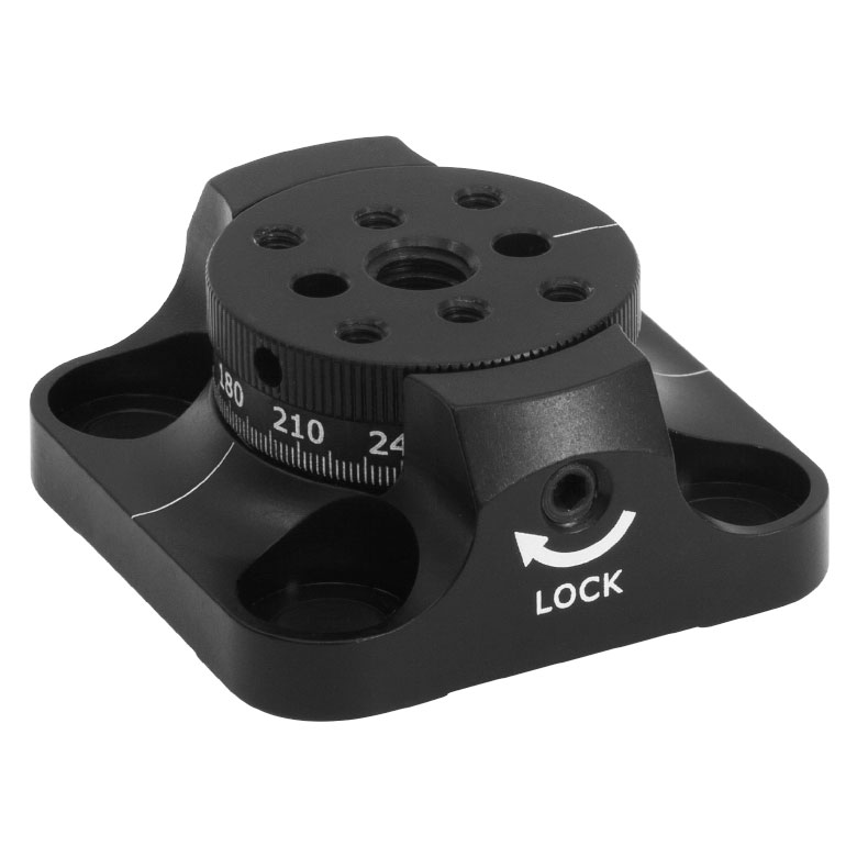 | 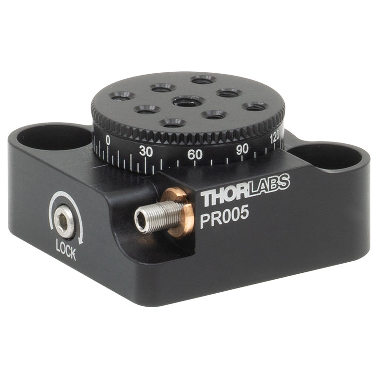 | 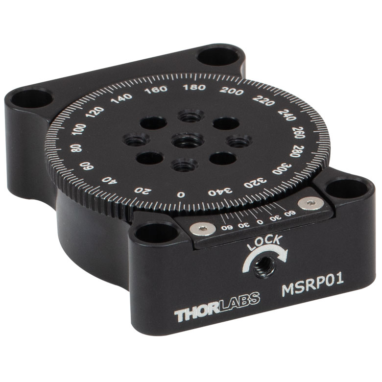 | 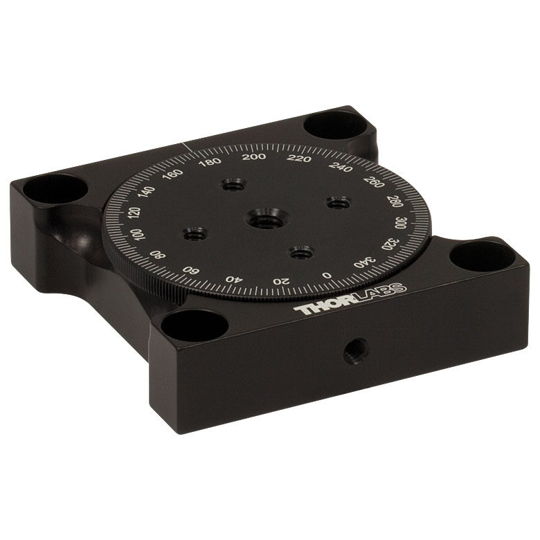 |  |  |
| Features | Standard | Two Hard Stops | ||||
| Additional Details | ||||||
| Manual Rotation Stages | ||||||
|---|---|---|---|---|---|---|
| Item # | XRNR1(/M) | XRR1(/M) | PR01(/M) | CR1(/M) | XYR1(/M) | OCT-XYR1(/M) |
| Click Photo to Enlarge |  |  |  | 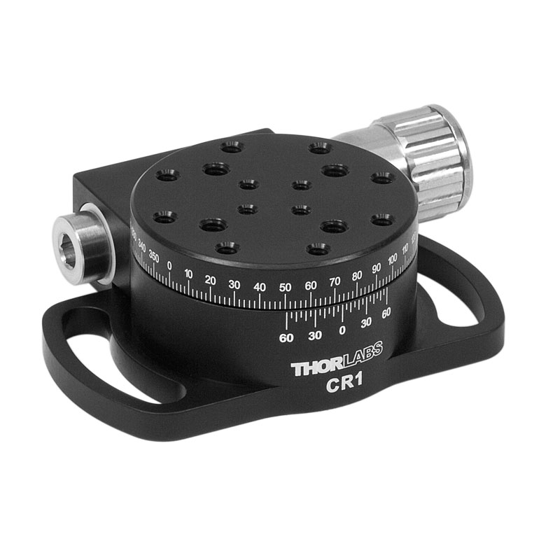 | 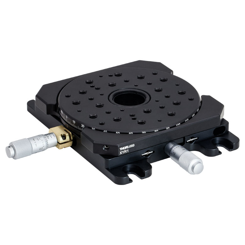 | 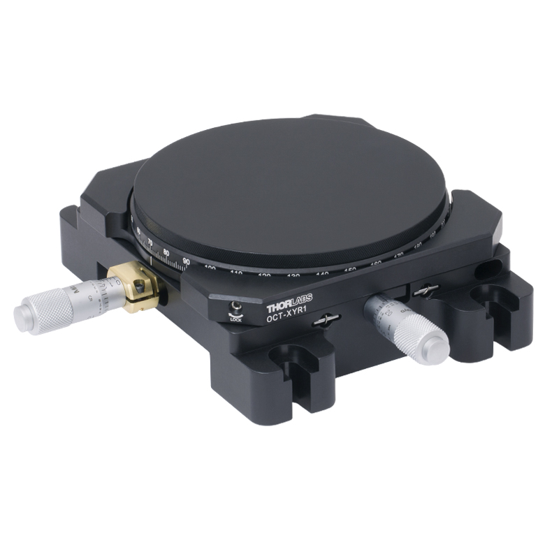 |
| Features | Fine Rotation Adjuster and 2" Wide Dovetail Quick Connect | Fine Rotation Adjuster and 3" Wide Dovetail Quick Connect | Fine Rotation Adjuster and SM1-Threaded Central Aperture | Fine Pitch Worm Gear | Rotation and 1/2" Linear XY Translation | |
| Additional Details | ||||||
電動回転マウント&ステージ
| Motorized Rotation Mounts and Stages with Central Clear Apertures | |||||
|---|---|---|---|---|---|
| Item # | DDR25(/M) | PDR1C(/M) | PDR1(/M) | PDR1V(/M) | PDXR1(/M) |
| Click Photo to Enlarge | 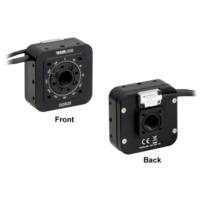 | 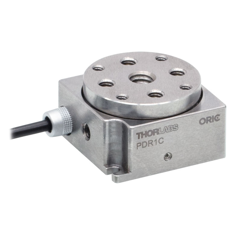 | 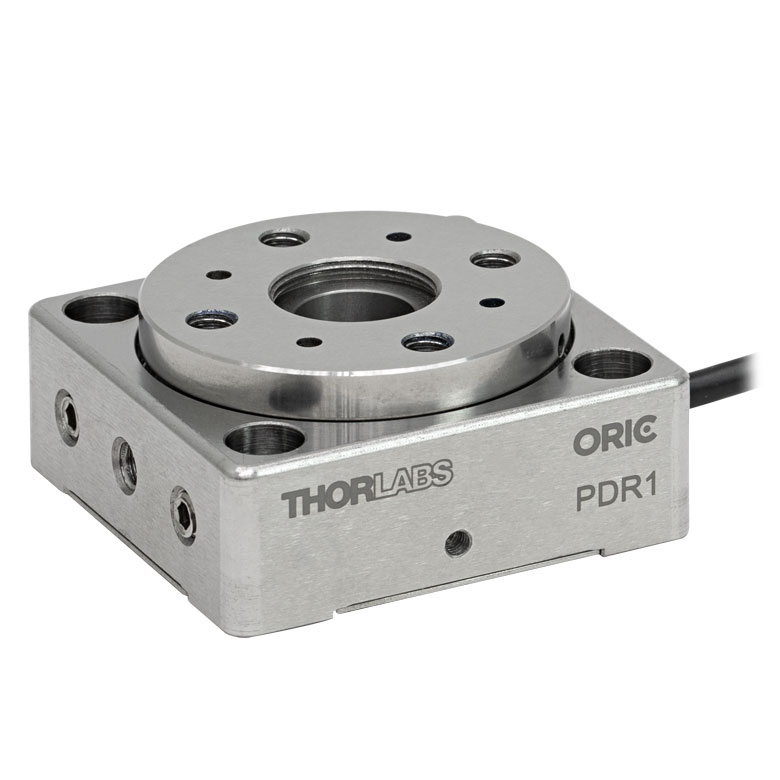 |  |  |
| Features | Compatible with SM05 Lens Tubes, 16 mm Cage System, & 30 mm Cage System | Compatible with 16 mm Cage System | Compatible with SM05 Lens Tubes & 30 mm Cage System | Vacuum-Compatible; Also Compatible with SM05 Lens Tubes & 30 mm Cage System | Compatible with SM05 Lens Tubes & 30 mm Cage System |
| Additional Details | |||||
| Motorized Rotation Mounts and Stages with Central Clear Apertures | |||||||
|---|---|---|---|---|---|---|---|
| Item # | K10CR1(/M) | PRM1Z8(/M)a | DDR100(/M) | ELL16 | ELL14 | ELL21(/M) | HDR50(/M) |
| Click Photo to Enlarge | 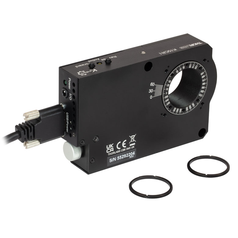 | 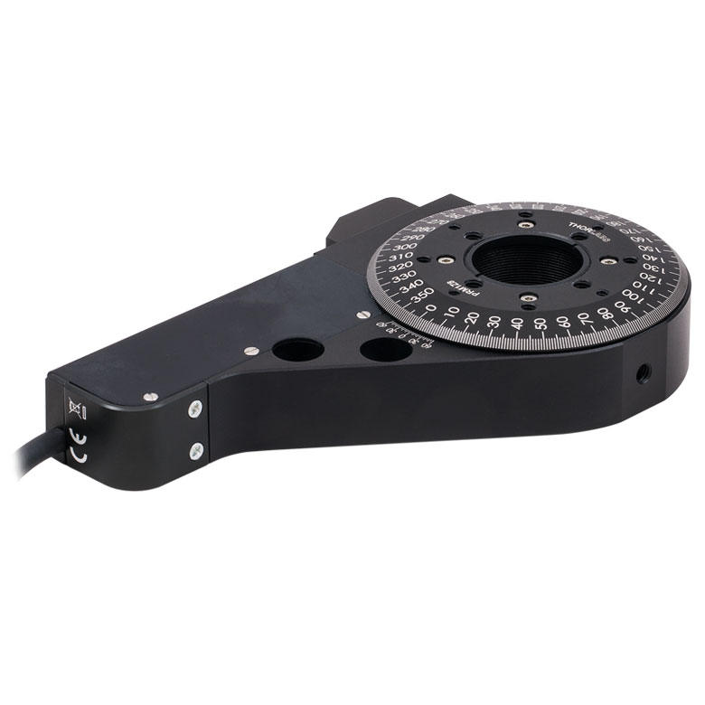 | 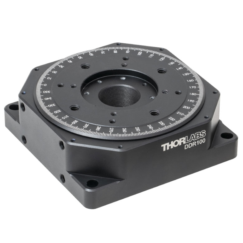 |  | 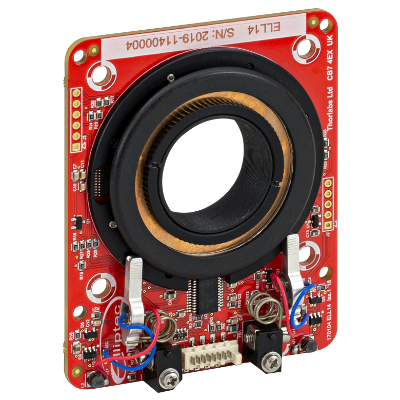 | 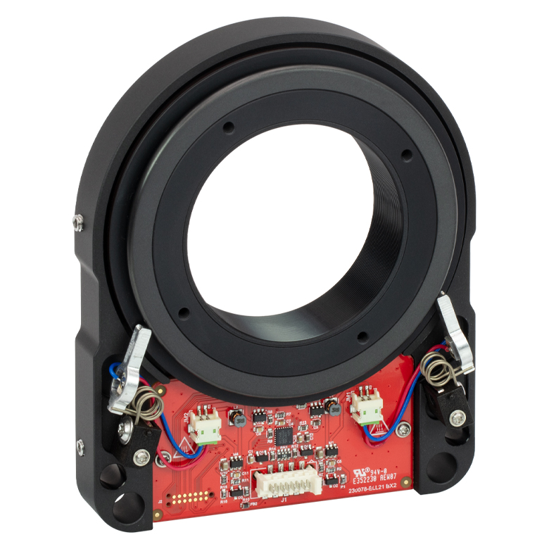 | 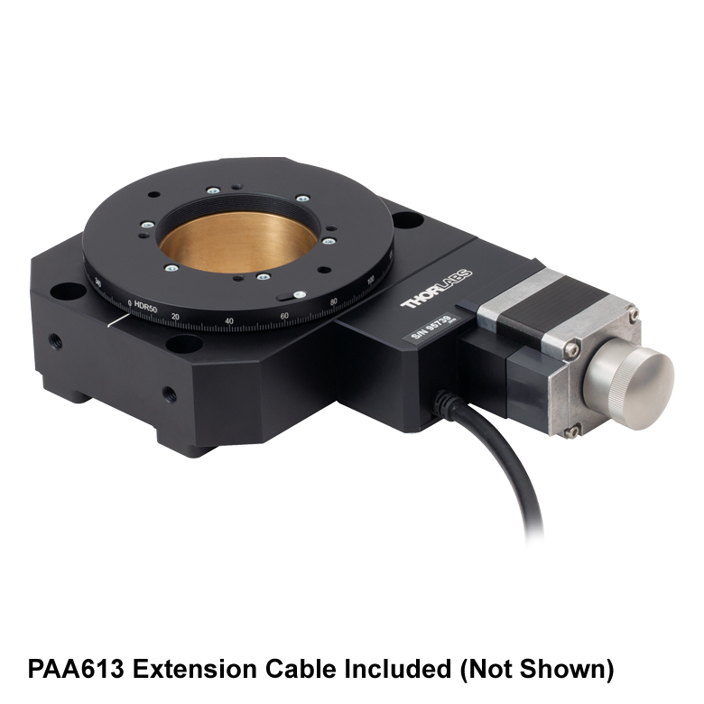 |
| Features | Compatible with SM1 Lens Tubes & 30 mm Cage System | Compatible with SM1 Lens Tubes, 16 mm Cage System, 30 mm Cage System | Compatible with SM05 Lens Tubes, Open Frame Design for OEM Applications | Compatible with SM1 Lens Tubes, Open Frame Design for OEM Applications | Compatible with SM2 Lens Tubes, Open Frame Design for OEM Applications | Compatible with SM2 Lens Tubes | |
| Additional Details | |||||||
| Motorized Rotation Mounts and Stages with Tapped Platforms | ||
|---|---|---|
| Item # | PRMTZ8(/M)a | ELL18(/M)b |
| Click Photo to Enlarge | 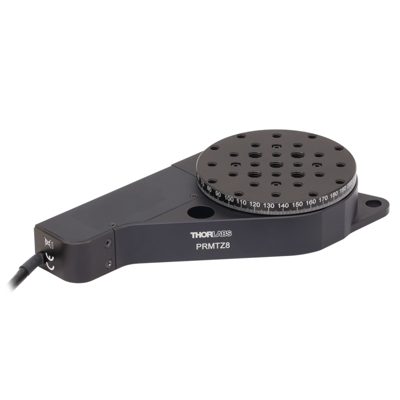 | 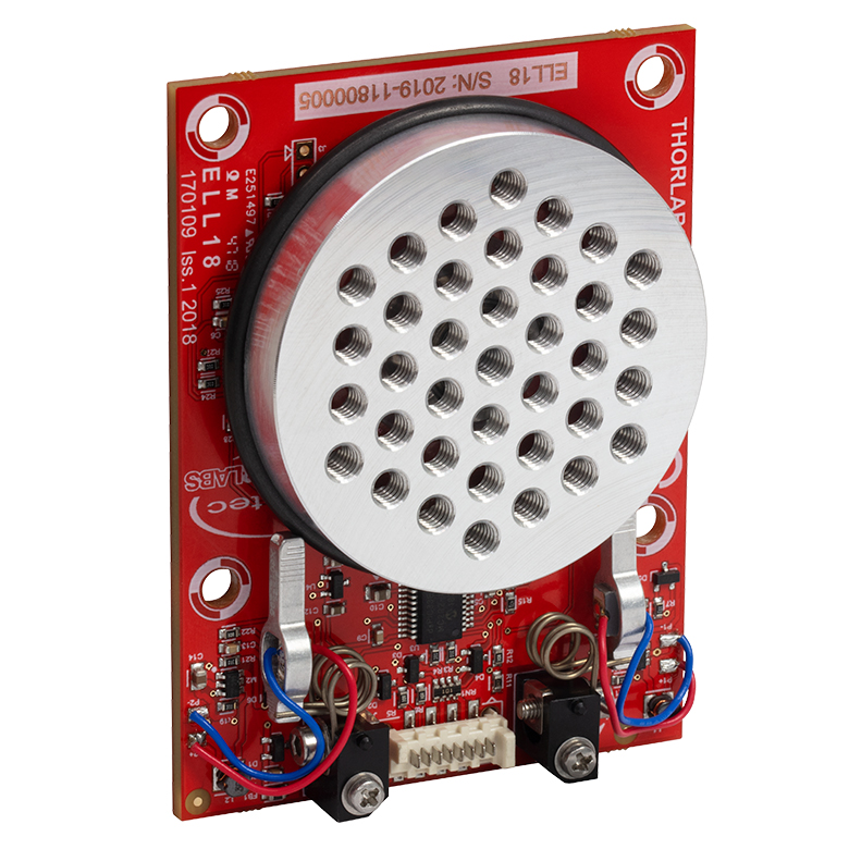 |
| Features | Tapped Mounting Platform for Mounting Prisms or Other Optics | Tapped Mounting Platform, Open Frame Design for OEM Applications |
| Additional Details | ||