 Products Home
キネマティックミラーマウント、2アジャスタ

- Kinematic Mirror Mounts for Ø7 mm, Ø10 mm, Ø1/2", Ø1", and Ø2" Optics
- Setscrew or SM-Threaded Optic Retention
- Angular Adjustment Ranges of ±3° or ±4°
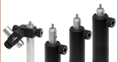
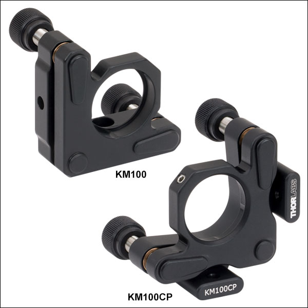
KM100
For Ø1" Optics
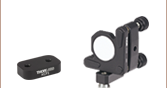
Application Idea
KM200T SM2-Threaded Thin Optic Mount with
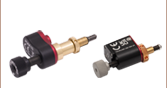
Dichroic Mirror and PIAK10 Piezo Inertia Actuator
KM100CP
For Ø1" Optics,
Post Centered
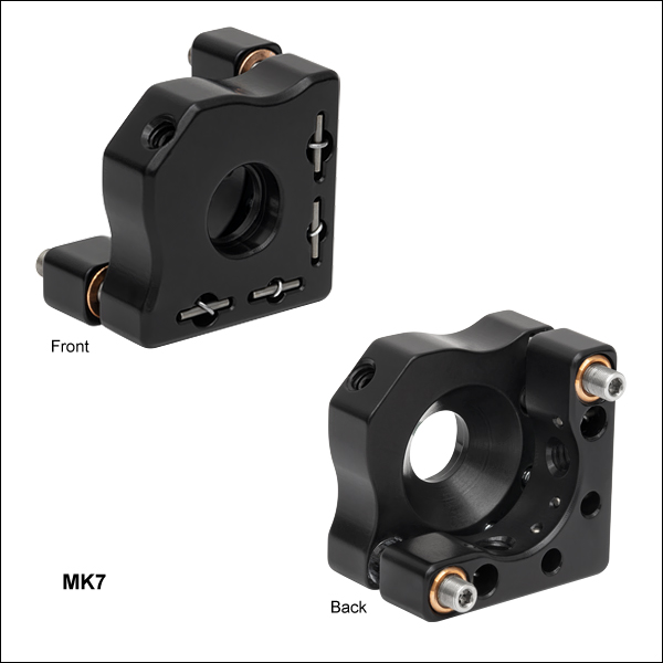
MK7
For Ø7 mm Optics
KM05T
For Ø1/2" Optics, SM05 Threaded


Please Wait

| Quick Links | |
|---|---|
| Optic Size | Mount Type |
| Ø7 mm | Mini-Series |
| Ø10 mm | Mini-Series |
| Ø1/2" | Mini-Series |
| Standard | |
| SM05-Threaded | |
| Ø1" | Standard |
| SM1-Threaded | |
| Ø2" | Standard |
| SM2-Threaded | |
| Hex Key Adjusters | |
特長
- 2重穴と止めネジによりØ7 mm、Ø10 mm、Ø12 mm~Ø12.7 mm(Ø1/2インチ)、Ø25 mm~Ø25.4 mm(Ø1インチ)、Ø50 mm~Ø50.8 mm(Ø2インチ)の光学素子を保持
- SMネジ付きマウントもご用意(薄型のØ12 mm~Ø12.7 mm(Ø1/2インチ)、Ø25 mm~Ø25.4 mm(Ø1インチ)、Ø50 mm~Ø50.8 mm(Ø2インチ)の光学素子、およびSMネジ付きコンポーネントの取付けが可能)
- キネマティック接触点に硬化スチール製インサートを挿入することで摩耗を低減
- リン青銅のブッシュとステンレススチール製の送りネジによりスムーズな調整が可能
- 黒色アルマイト加工アルミニウム製
- 取付け穴を選ぶことで、右手系または左手系の選択が可能
当社の2アジャスターキネマティックミラーマウントには、ミラーを2重穴と止めネジで保持するタイプと、SMネジ付き取付け穴で保持するタイプがございます。後者は薄型光学コンポーネントを低応力の負荷で取り付けることができ、またSMネジ付きコンポーネントの取付けも可能です。マウントの角度調整範囲は±4°(Ø50 mm~Ø50.8 mmマウントは±3°)で、右手系と左手系のどちらの向きにも取り付けられます。ミニシリーズのマウントはØ6 mmミニシリーズポストに、標準型マウントおよびSMネジ付きマウントはØ12 mmおよびØ12.7 mm(Ø1/2インチ)ポストに取り付けられます。ミラーを2重穴と止めネジで保持するタイプのØ12 mm~Ø12.7 mm(Ø1/2インチ)、Ø25 mm~Ø25.4 mm(Ø1インチ)、およびØ50 mm~Ø50.8 mm(Ø2インチ)マウントには、ポストセンタリングプレートの付いた製品もご用意しています。これらのマウントでは、45°で入射するビームの光学テーブルの穴パターンへのアライメントが容易になります。
Ø25 mm~Ø25.4 mm(Ø1インチ)およびØ50 mm~Ø50.8 mm(Ø2インチ)光学素子用マウントのノブは、取り外して送りネジ先端の六角ソケットを露出させることができます(右の動画をご覧ください)。ノブには貫通穴があるため、ノブを取り付けたまま六角レンチで微調整することもできます。
ミニシリーズおよび標準型マウント
ミニシリーズおよび標準型マウントでは、先端がナイロン製の固定ネジと2重穴構造の取付け穴を用いて、3点でミラーを固定します。また、当社のマウントの中でもご要望の高いKM100とKM200については、広帯域誘電体コーティング付きミラーをセットにして割引価格でご提供しております。ご用意しているセットについては下記の表をご参照ください。各コーティングの一般的な仕様と反射スペクトルの詳細については、上の「ミラー情報」タブをクリックしてご覧ください。
SMネジ付きマウント
ミラー取付け穴にSM05ネジ、SM1ネジまたはSM2ネジの付いた製品をご用意しています。これらには光学素子を固定するための固定リングが2つ付属しており、薄型の光学素子を低応力の負荷で取り付けることができます。また、SMネジ付きコンポーネントの取り付けも可能です。
当社では様々な種類の2アジャスタおよび3アジャスタミラーマウントをご用意しています。それらの中には、Ø75 mm~Ø76.2 mm(Ø3インチ)やØ101.6 mm(Ø4インチ)光学素子用のマウントのほか、安定性の高いPolaris®ミラーマウントもございます。
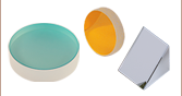
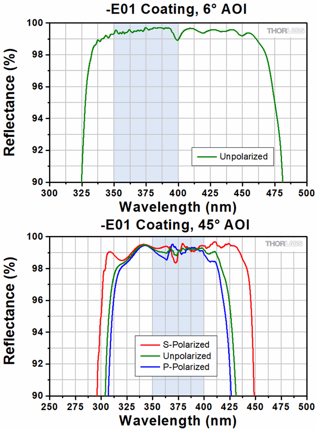
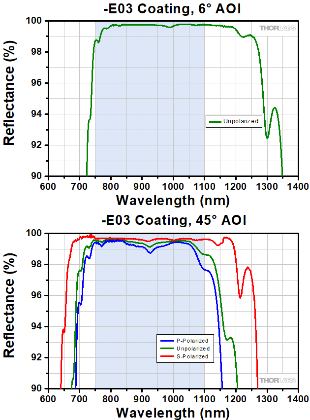
KMシリーズのキネマティックミラーマウントに取り付け済みの広帯域誘電体コート付きミラーの情報に関しては、こちらをご覧ください。一般的な仕様、スペクトル範囲、および45°の無偏光入射ビームに対する反射率は下に掲載されています。
| Common Specifications | |
|---|---|
| Substrate Material | Fused Silica |
| Flatness | λ/10 |
| Surface Quality | 10-5 Scratch- Dig |
| Back Surface | Fine Ground |
| Clear Aperture | > 90% of Diameter |
| Thickness Tolerance | ±0.2 mm |
| Diameter Tolerance | +0.00/-0.10 mm |
| Mirror | Spectral Range (Click for Plot) | Damage Threshold | |
|---|---|---|---|
| UV Laser Mirror (KM100-E01) | 350 - 400 nm | Pulse | 1 J/cm2 (355 nm, 10 ns, 10 Hz, Ø0.373 mm) |
| Visible Laser Mirror (KM100-E02) (KM200-E02) | 400 - 750 nm | Pulse | 0.25 J/cm2 (532 nm, 10 ns, 10 Hz, Ø0.803 mm) |
| CWa,b | 550 W/cm (532 nm, Ø1.000 mm) | ||
| Near IR Laser Mirror (KM100-E03) (KM200-E03) | 750 - 1100 nm | Pulse | 1 J/cm2 (810 nm, 10 ns, 10 Hz, Ø0.133 mm), 0.5 J/cm2 (1064 nm, 10 ns, 10 Hz, Ø0.433 mm), 0.205 J/cm2 (800 nm, 99 fs, 1000 Hz, Ø0.166 mm) |
| CWa,b | 10 kW/cm (1070 nm, Ø0.971 mm) | ||
| 1.28 - 1.6 µm Laser Mirror (KM100-E04) | 1280 - 1600 nm | Pulse | 2.5 J/cm2 (1542 nm, 10 ns, 10 Hz, Ø0.181 mm) |
| CWa,b | 350 W/cm (1540 nm, Ø1.030 mm) | ||
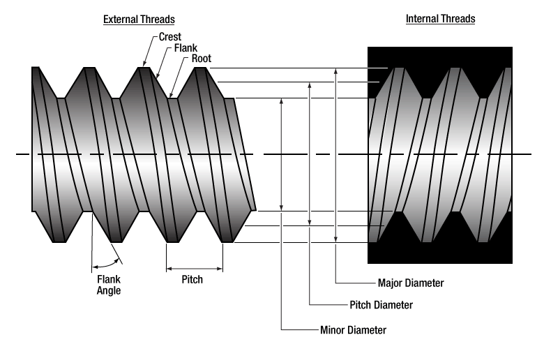
| SM05 Threading: Ø1/2" Lens Tubes, 16 mm Cage Systems | |||
|---|---|---|---|
| External Thread, 0.535"-40.0 UNS-2A | Internal Thread, 0.535"-40.0 UNS-2B | ||
| Max Major Diameter | 0.5340" | Min Major Diameter | 0.5350" |
| Min Major Diameter | 0.5289" | Min Pitch Diameter | 0.5188" |
| Max Pitch Diameter | 0.5178" | Max Pitch Diameter | 0.5230" |
| Min Pitch Diameter | 0.5146" | Min Minor Diameter (and 83.3% of Thread) | 0.508" |
| Max Minor Diameter | 0.5069" | Max Minor Diameter (and 64.9% of Thread) | 0.514" |
| RMS Threading: Objective, Scan, and Tube Lenses | |||
|---|---|---|---|
| External Thread, 0.800"-36.0 UNS-2A | Internal Thread, 0.800"-36.0 UNS-2B | ||
| Max Major Diameter | 0.7989" | Min Major Diameter | 0.8000" |
| Min Major Diameter | 0.7934" | Min Pitch Diameter | 0.7820" |
| Max Pitch Diameter | 0.7809" | Max Pitch Diameter | 0.7866" |
| Min Pitch Diameter | 0.7774" | Min Minor Diameter (and 83.3% of Thread) | 0.770" |
| Max Minor Diameter | 0.7688" | Max Minor Diameter (and 64.9% of Thread) | 0.777" |
| C-Mount Threading: Machine Vision Lenses, CCD/CMOS Cameras | |||
|---|---|---|---|
| External Thread, 1.000"-32.0 UN-2A | Internal Thread, 1.000"-32.0 UN-2B | ||
| Max Major Diameter | 0.9989" | Min Major Diameter | 1.0000" |
| Min Major Diameter | 0.9929" | Min Pitch Diameter | 0.9797" |
| Max Pitch Diameter | 0.9786" | Max Pitch Diameter | 0.9846" |
| Min Pitch Diameter | 0.9748" | Min Minor Diameter (and 83.3% of Thread) | 0.966" |
| Max Minor Diameter | 0.9651" | Max Minor Diameter (and 64.9% of Thread) | 0.974" |
| SM1 Threading: Ø1" Lens Tubes, 30 mm Cage Systems | |||
|---|---|---|---|
| External Thread, 1.035"-40.0 UNS-2A | Internal Thread, 1.035"-40.0 UNS-2B | ||
| Max Major Diameter | 1.0339" | Min Major Diameter | 1.0350" |
| Min Major Diameter | 1.0288" | Min Pitch Diameter | 1.0188" |
| Max Pitch Diameter | 1.0177" | Max Pitch Diameter | 1.0234" |
| Min Pitch Diameter | 1.0142" | Min Minor Diameter (and 83.3% of Thread) | 1.008" |
| Max Minor Diameter | 1.0068" | Max Minor Diameter (and 64.9% of Thread) | 1.014" |
| SM30 Threading: Ø30 mm Lens Tubes | |||
|---|---|---|---|
| External Thread, M30.5 x 0.5 – 6H/6g | Internal Thread, M30.5 x 0.5 – 6H/6g | ||
| Max Major Diameter | 30.480 mm | Min Major Diameter | 30.500 mm |
| Min Major Diameter | 30.371 mm | Min Pitch Diameter | 30.175 mm |
| Max Pitch Diameter | 30.155 mm | Max Pitch Diameter | 30.302 mm |
| Min Pitch Diameter | 30.059 mm | Min Minor Diameter (and 83.3% of Thread) | 29.959 mm |
| Max Minor Diameter | 29.938 mm | Max Minor Diameter (and 64.9% of Thread) | 30.094 mm |
| SM1.5 Threading: Ø1.5" Lens Tubes | |||
|---|---|---|---|
| External Thread, 1.535"-40 UNS-2A | Internal Thread, 1.535"-40 UNS-2B | ||
| Max Major Diameter | 1.5339" | Min Major Diameter | 1.535" |
| Min Major Diameter | 1.5288" | Min Pitch Diameter | 1.5188" |
| Max Pitch Diameter | 1.5177" | Max Pitch Diameter | 1.5236" |
| Min Pitch Diameter | 1.5140" | Min Minor Diameter (and 83.3% of Thread) | 1.508" |
| Max Minor Diameter | 1.5068" | Max Minor Diameter (and 64.9% of Thread) | 1.514" |
| SM2 Threading: Ø2" Lens Tubes, 60 mm Cage Systems | |||
|---|---|---|---|
| External Thread, 2.035"-40.0 UNS-2A | Internal Thread, 2.035"-40.0 UNS-2B | ||
| Max Major Diameter | 2.0338" | Min Major Diameter | 2.0350" |
| Min Major Diameter | 2.0287" | Min Pitch Diameter | 2.0188" |
| Max Pitch Diameter | 2.0176" | Max Pitch Diameter | 2.0239" |
| Min Pitch Diameter | 2.0137" | Min Minor Diameter (and 83.3% of Thread) | 2.008" |
| Max Minor Diameter | 2.0067" | Max Minor Diameter (and 64.9% of Thread) | 2.014" |
| SM3 Threading: Ø3" Lens Tubes | |||
|---|---|---|---|
| External Thread, 3.035"-40.0 UNS-2A | Internal Thread, 3.035"-40.0 UNS-2B | ||
| Max Major Diameter | 3.0337" | Min Major Diameter | 3.0350" |
| Min Major Diameter | 3.0286" | Min Pitch Diameter | 3.0188" |
| Max Pitch Diameter | 3.0175" | Max Pitch Diameter | 3.0242" |
| Min Pitch Diameter | 3.0133" | Min Minor Diameter (and 83.3% of Thread) | 3.008" |
| Max Minor Diameter | 3.0066" | Max Minor Diameter (and 64.9% of Thread) | 3.014" |
| SM4 Threading: Ø4" Lens Tubes | |||
|---|---|---|---|
| External Thread, 4.035"-40 UNS-2A | Internal Thread, 4.035"-40.0 UNS-2B | ||
| Max Major Diameter | 4.0337" | Min Major Diameter | 4.0350" |
| Min Major Diameter | 4.0286" | Min Pitch Diameter | 4.0188" |
| Max Pitch Diameter | 4.0175" | Max Pitch Diameter | 4.0245" |
| Min Pitch Diameter | 4.0131" | Min Minor Diameter (and 83.3% of Thread) | 4.008" |
| Max Minor Diameter | 4.0066" | Max Minor Diameter (and 64.9% of Thread) | 4.014" |

Click to Enlarge
Old KM100 Packaging
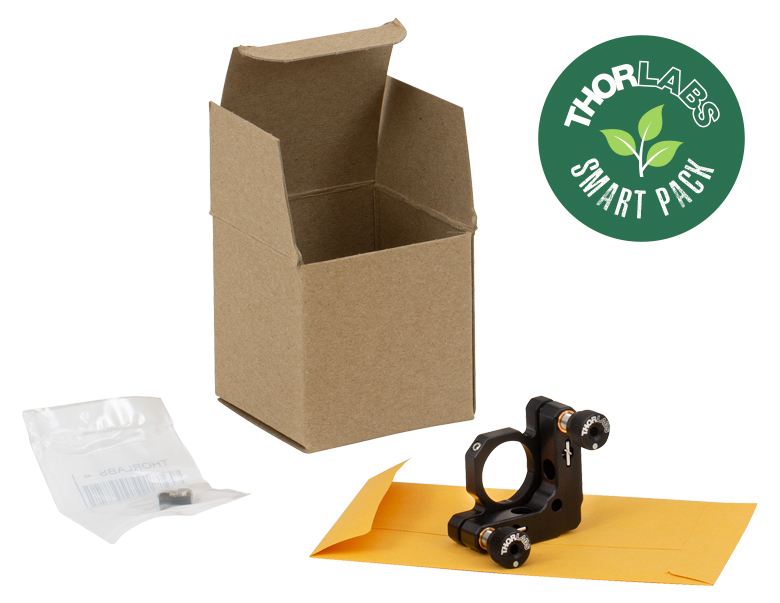
Click to Enlarge
New KM100 Packaging
Smart Pack Goals
- Reduce Weight of Packaging
- Increase Usage of Recyclable Materials
- Improve Packing Integrity
- Decrease Shipping Costs
Thorlabs' Smart Pack Initiative is aimed at minimizing waste while providing adequate protection for our products. By eliminating any unnecessary packaging, implementing design changes, and utilizing eco-friendly materials, this initiative seeks to reduce the environmental impact of our product packaging.
The new KM100 packing box and envelope are made of compostable, 100% recycled paper products. The transition from plastic bubble wrap to recycled paper results in a 29.33% reduction in the amount of CO2 produced per kg of packing materials. As we move through our product line, we will indicate re-engineered, eco-friendly packaging with our Smart Pack logo.
| Posted Comments: | |
mahesh swami
(posted 2024-11-19 19:24:04.267) For KM100 mirror mount how much is the corss-talk between pitch and yaw movements. EGies
(posted 2024-11-20 01:57:11.0) Thank you for contacting Thorlabs. I have reached out to you directly regarding this. Future requests for additional specs/data can be made by emailing us directly at techsupport@thorlabs.com. Tobias Ruff
(posted 2024-08-24 13:22:42.43) Dear Ladies and Gentlemen,
The KM100 mirror mount I bought with Thorlabs came without a thread as far as I can see.
How can I attach it to one of Thorlab's optical posts?
Kind regards
Tobi jdelia
(posted 2024-08-26 01:12:05.0) Thank you for contacting Thorlabs. Our KM100 has a #8 (M4) counterbore for mounting to a post using either an 8-32 or M4 cap screw depending on whether your post is imperial or metric. Marina Servol
(posted 2023-09-13 09:48:19.5) Hello,
the KM100 mirror mounts needs a M4 screw to be mounted on posts. Could you give me the threaded length the M4 screw should be (not including the cap part) ? Do you sell these items ?
Thanks a lot jdelia
(posted 2023-09-19 01:06:47.0) Thank you for contacting Thorlabs. The counterbore thickness on the KM100 is 4.32 mm, so the threading on the cap screw you use would just have to be longer than that. Please keep in mind that you would not want the screw to be so long that it uses up the entire thread depth of the post onto which you are mounting it. Bart Tromp
(posted 2023-03-24 22:19:29.733) For the KM05/M; is the +/- 4deg angular range in optical or mechanical degrees? jdelia
(posted 2023-03-27 04:28:12.0) Thank you for contacting Thorlabs. The +/- 4 deg angular range for the KM05/M refers to the mechanics adjustment range, not optical. Ruggero Milazzo
(posted 2021-11-04 09:33:53.477) To whom it may concern,
I am interested to KM100CP and I would like to have the possibility to control movements (translation and rotation) in a reproducible way. Is it possible to add one or more micrometer (or a goniometer)? Maybe in the place of the Adjustment Knobs?
Thanks azandani
(posted 2021-11-04 04:06:05.0) Hello Ruggero, thank you for contacting Thorlabs. It is certainly possible to add a micrometer in place of the adjusters used. The KM100CP features 1/4"-80 adjusters that yield +/- 4 degrees of angular adjustment. Because of this threading, the micrometer option will be our DM22 Manual Differential Drive which can be found here: ( https://www.thorlabs.com/newgrouppage9.cfm?objectgroup_id=1247&pn=DM22 ). user
(posted 2019-09-13 18:58:02.77) On the KM100CP, it doesn't look like there is enough room to get an 8-32 screw into the mounting hole. Do you remove the face plate to get the screw in? llamb
(posted 2019-09-14 12:44:57.0) Thank you for contacting Thorlabs. The KM100CP is designed for mounting #8-32 setscrews (included with our optical posts) in through the bottom of the mounting hole. This part is not designed for cap screws. As you have not left a contact email, feel free to reach out to techsupport@thorlabs.com with any other questions. Yuan Liu
(posted 2019-07-25 12:24:34.903) Dear Thorlabs support,
Do you have the temperature stability data for KM100? I am trying to compare KM100 to POLARIS K1T1 (which has temperature data).
If no public data is available now. Could you please email me the data. Thanks!
Best regards,
Yuan YLohia
(posted 2019-07-25 03:30:17.0) Hello Yuan, thank you for contacting Thorlabs. I have reached out to you directly with this information. Such information can be requested by emailing techsupport@thorlabs.com. Patrick Lee
(posted 2019-03-31 11:55:15.48) Hi, for KM100, where is axis of rotation/tilt ? YLohia
(posted 2019-04-01 11:52:41.0) Hello, thank you for contacting Thorlabs. The KM100 rotates about the ball bearing in the corner of the mount with no adjuster. I have reached out to you with a drawing to make this a little clearer. user
(posted 2019-03-22 15:04:06.97) The description and images for this part indicates the two post mounting holes are tapped/threaded, yet the PDF drawing file indicates that the holes are thru. The KM05T properly indicates that the holes are #8-32 tapped.
I anticipated that the holes would be thru (which I can ream out), however, I suggest that you update the drawing text to reflect the fact that the post mounting holes are in fact tapped and not thru. llamb
(posted 2019-03-22 03:37:05.0) Thank you for your feedback. The PDF drawing for the KM05 calls out an "8-32 MOUNTING HOLE THRU". We intended this to explain that the KM05 features an #8-32 thread (as opposed to a smooth or counterbored hole) that goes through the entire thickness of the back plate, as opposed to a blind thread with a limited thread depth. This has been forwarded to our marketing team for further review to help clarify the product specifications. werner.engel
(posted 2018-11-10 13:09:19.26) Hallo! Ich bin gerade dabei, für einen Antrag ein optisches Setup zu erstellen. Dabei wäre es extrem gut, nach dem Zeichnen der Anlage, gleich eine Stückliste mit Preisen zu bekommen. Und wenn das Ganze in 3D wäre, könnte ich auch gleich alle optomechanical parts dazu bestellen.
Ist schon mal an eine eigene 3D-Software
gedacht worden mit der man so ein Experiment zeichnen kann - und auch optisch ansprechend darstellen kann?
LG, Werner Engel
engel@fotec.at nreusch
(posted 2018-11-21 03:56:52.0) Thank you very much for your inquiry and your suggestion. Yes, we have already discussed such an option internally. However, there are solutions that already offer this feature: Autodesk Fusion 360 or FreeCAD with a plugin called assembly2. Of course, these possibilities do not offer an order option.
German: Vielen Dank für Ihre Anfrage und Ihren Vorschlag. Ja, eine solche Option haben wir intern bereits diskutiert. Es gibt allerdings Lösungen, die diese Funktion bereits bieten: Autodesk Fusion 360 oder FreeCAD mit einem Plugin namens assembly2. Eine Bestelloption bieten diese Möglichkeiten natürlich nicht. user
(posted 2018-05-04 10:38:58.05) I recently designed a system to use Thorlabs KM05 mounts that my company purchased a few years ago. I just learned that the thickness of the base of these older mounts (0.408") is greater than the thickness listed on the current Thorlabs print for the KM05 (0.31"). However, an even older Thorlabs mount in our possession (a KM05FR) does have the "newer" thinner base thickness (0.31"). Therefore, before I order replacement KM05's to go into my custom hardware, could you please confirm the thickness of the mounting base of the KM05 currently sold by Thorlabs? Again, the old thickness was 0.408", and the new thickness is reported to be 0.31". Thank you. YLohia
(posted 2018-05-04 02:12:30.0) Hello, thank you for contacting Thorlabs. Yes, to confirm, the current thickness is indeed 0.31". user
(posted 2016-03-01 17:15:43.513) We wants to think of KM05CP for our application,but what would be max AOI for the mount? We are concerned that beam is clipped by edge of the mount... besembeson
(posted 2016-03-02 03:48:56.0) Response from Bweh at Thorlabs USA: This should be ~72deg. rjh1205
(posted 2014-06-05 10:03:00.437) Hi. I am using KM 100 with mirror now, and I just wonder how much tilted by turning the adjuster. Is there any data about this? Thanks. besembeson
(posted 2014-06-05 06:10:01.0) A response from Bweh E at Thorlabs Newton-USA: This can be tilted up to +/- 4deg. The resolution is 0.5deg per revolution for the 80 TPI precision adjusters.
If you have a special requirement based on your application, let me know and I will look into this for you please. takeshi.matsuoka1
(posted 2014-01-10 14:06:39.063) Could you add a vacuum compatible version to your product line? The specification is,
2. made by Al
3. UNANOSDIZED Al
4. no brass
5. All parts is cleaned in acetone with an
ultrasonic washing machine before assembling.
6. use vacuum compatible grease cdaly
(posted 2014-01-16 08:04:20.0) Response from Chris at Thorlabs: Thank you for your inquiry. We will be implementing quite a few vacuum compatible, unanodized parts to our standard catalog offerings int he following months, including a version of the 3 axis kinematic mount KS1 (KS1V). The 2 inch mounts KS2 and KM200 are not among the list of avacuum compatible parts scheduled to be released, but we can still offer a version as a custom. We will contact you directly to discuss this further. tcohen
(posted 2012-04-02 09:59:00.0) A response from Tim at Thorlabs: We have already generated data on both the KS and the Polaris and there is a clear difference between the two in terms of returning to original position after temperature cycling. You are certainly right that this information will be useful for selecting between our mounts. We are currently working towards accumulating more data and integrating it into our web presentation and we look forward to having this data available for our customers soon! user
(posted 2012-03-31 18:55:40.0) A response to Tim at Thor Labs- Yes exactly, this is what I was requesting. I don't mind helping you improve your website because it ultimately helps me too and, trust me, there are a lot of other people who would like to have this too. It is much easier to select a mount if all the information is available. Please remember to do both the KS1 and the KM100. If you have more time you might as well do the larger mounts too. PS. I am not a Thor Labs Employee regardless of what everyone is thinking but I do know Alex, John and Brian from the good old days.... tcohen
(posted 2012-03-22 09:42:00.0) Response from Tim at Thorlabs: Thank you for helping us improve our web presentation! We are currently testing the thermal stability of the KM series to help distinguish between our KM and Polaris mounts. We will post an update shortly with the data. In the meantime if you would like to discuss your application or the products in further detail, please feel free to contact us at techsupport@thorlabs.com. user
(posted 2012-03-21 18:27:09.0) Hello Buki what I was really asking about is if you can post on your website, thermal test data on the KM100 and KS1. it would be helpful for comparing with the steel mount called Polaris. bdada
(posted 2012-03-21 18:38:00.0) Response from Buki at Thorlabs:
Thank you for your feedback. It seems you are comparing the KM series mount to the Polaris. Please use the link below and refer to the "Test Data" tab to see the results of the temperature cycling test.
http://thorlabs.com/NewGroupPage9.cfm?ObjectGroup_ID=3912&pn=POLARIS-K05#5462
We would like to discuss your application further so we can ensure you select the appropriate optical mount. Please contact TechSupport@thorlabs.com to continue this discussion. user
(posted 2012-03-21 01:28:57.0) I like this mount but would like if you could add the thermal test you did on your steel mount so I can compare. It seems as though this mount is just as stable as the steel mount and I can buy 3 for the price of 1 steel mount. Please prove me wrong by showing the test data. jjurado
(posted 2011-05-31 11:27:00.0) Response from Javier at Thorlabs to sshosseini: Thank you very much for your feedback. We will review the design of our kinematic mirror holders and will keep you updated of any changes. sshosseini
(posted 2011-05-20 17:24:50.0) Hi,
I use the 1" and 2" mirror mounts as lens mounts most times. It is perfect and I can adjust my lenses using the nubs. But since the post holder on the mount is not "exactly" in the center of the opening, i need to combine the a BA1 underneath the post so i can adjust the post just a tiny bet. Again, the difference is a tiny bet but it is important when aligning the lens and It would be helpful if you change the design and have the post screw clearance "exactly" in the center of the opening.
~Sona paulshamilton
(posted 2010-12-10 18:12:55.0) I agree with Isandstrom - removable knobs on the KM05 would be very useful. klee
(posted 2009-09-29 18:03:44.0) A response from Ken at Thorlabs to diogenes500: Thank you for your feedback. Your suggestion has been forwarded to our engineering department for consideration. diogenes500
(posted 2009-09-28 19:06:02.0) It would be nice if there were markers on the outer edges of the km100 which denoted the middle position of the mirror (horizontal and vertical). When I am measuring with a ruler on an optical table it is difficult to gauge where the mirror center is, and this would help a good deal. Laurie
(posted 2008-04-22 16:46:18.0) Response from Laurie @ Thorlabs to lsandstrom: After looking into your suggestion a bit further, it would be possible for us to meet your needs through a special request. The KM05 that you inquired about has 3/16"-100 adjusters as does our KMS. Therefore, we could replace the adjusters on our KM05 with the longer adjusters and removable knobs from the KMS. If you would be interested in such an item, please contact our technical support staff at 973-300-3000. Laurie
(posted 2008-04-21 12:00:57.0) Response from Laurie at Thorlabs to lsandstrom: Thank you for your suggestion concerning removable knobs for our KM05 mounts. I will pass this information on to our mechanics group so that they can consider implementing it in the future. Thanks again for taking the time to provide feedback about how to improve our product line to serve you better. lsandstrom
(posted 2008-04-08 22:27:41.0) It would appreciate removable similar knobs on the KM05 as on the KM100 solarmayi
(posted 2008-02-18 01:58:26.0) GOOD TechnicalMarketing
(posted 2007-10-15 17:03:44.0) As requested, some basic information about the mirrors that come premounted in the KM series of kinematic mounts has been added to this page. Look under the "Mirror Info" tab. Also, the tab contains a link to the complete broadband dielectric mirror presentation. Thank you for submitting this excellent suggestion. As always we appreciate any feedback that allows us to improve the usefulness of our presentation. We are currently working on making the presentation feedback form more user friendly, but for now please consider creating another tab in your browser instead of navigating away from the presentation feedback form. acable
(posted 2007-10-12 20:34:23.0) It really hurts to type in a long reply and then go to check something out only to find the input screen has been wiped clean.
2nd try...
Please add reflectivity curves to the presentation and consider adding both a "Mirror Specifications" tab as well as a link to the full presentaion on th mirrors.
Also the Related Items tab should show all the other mirror mounts the Thorlabs offers, right i notic that the GM100 and VM1 are missing. |

 ズーム
ズーム
Click to Enlarge
7 mm光学素子PF03-03-P01を取り付けたキネマティックミラーマウントMK7(/M)
- 厚さ1.00 mm以上のØ7 mm光学素子の取り付けが可能
- コンパクトな設置面積:20.0 mm x 13.2 mm(公称値)
- 角度範囲:±4°
- 分解能:2つのM2.5 x 0.20アジャスタは、1回転に付き13.4 mrad(0.76°)の調整が可能
- 2つのM3取付け穴により右手系、左手系のどちらも構成可能
ミニシリーズキネマティックミラーマウントMK7/Mは、省スペースが要求されるオプトメカニクスのセットアップで、Ø7 mmの光学素子を取り付けられるように設計されています。MK10/MおよびMK05/Mと同様に、こちらの2アジャスタ付きマウントの設置面積は20.0 mm x 13.2 mm(公称値)で、当社のキネマティックマウントの中では最小です。ミラーは、先端がナイロン製の固定ネジと2重穴との組合せで、3点支持で固定されます。先端がナイロン製の止めネジ(セットスクリュ)と2個のM2.5 x 0.20アジャスターネジのどちらにも、1.3 mm(0.050インチ)六角レンチ(付属しておりません)が使用可能です。下記でご紹介しているつまみネジ型の0.050インチ(1.3 mm)六角レンチは調整が簡単なので、当社ではこちらのご使用をお勧めしています。また、アジャスターネジを任意の位置で固定したり、ハードストップを構成したりするために、固定用カラーとスパナレンチもご用意しております。
右手系、左手系のどちらも構成できるよう、マウントにはM3取付け穴が90°の位置に2つ付いており、当社のØ6 mmミニシリーズポストに取り付けられます。Ø6 mmポストは、ミニシリーズポストホルダを用いることで、ミニシリーズブレッドボードに取り付けることができます。

 ズーム
ズーム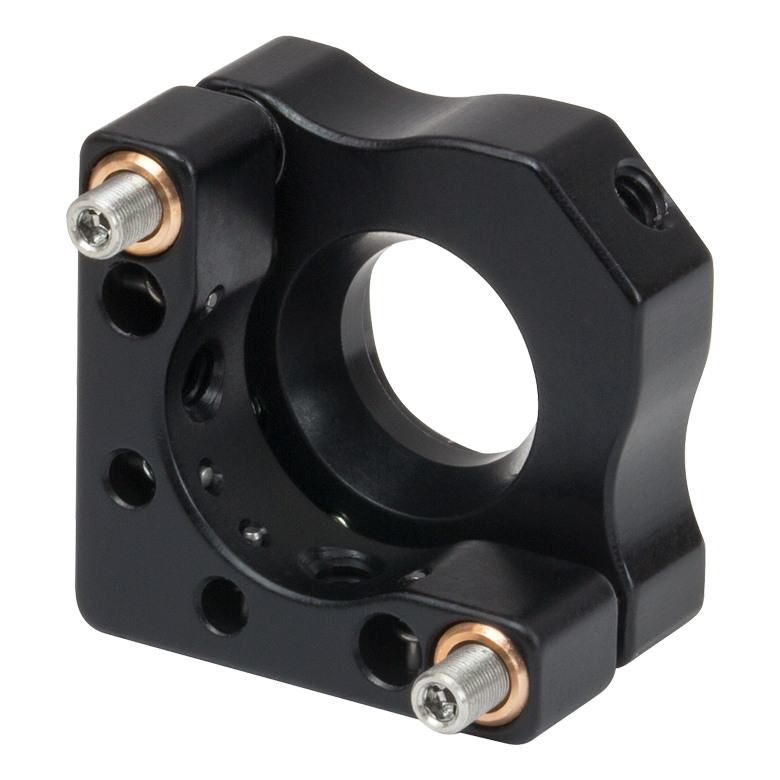
Click to Enlarge
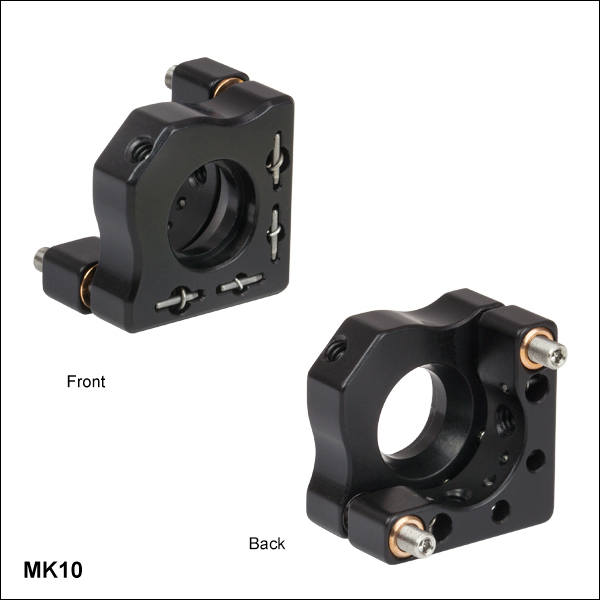
マウントMK10(/M)の背面
- 厚さ1.00 mm以上のØ10 mm光学素子の取り付けが可能
- コンパクトな設置面積:20.0 mm x 13.2 mm(公称値)
- 角度範囲:±4°
- 分解能:2つのM2.5 x 0.20アジャスタは、1回転に付き13.4 mrad(0.76°)の調整が可能
- 2つのM3取付け穴により右手系、左手系のどちらも構成可能
ミニシリーズキネマティックミラーマウントMK10/Mは、省スペースが要求されるオプトメカニクスのセットアップで、Ø10 mmの光学素子を取り付けられるように設計されています。MK7/MおよびMK05/Mと同様に、こちらの2アジャスタ付きマウントの設置面積は20.0 mm x 13.2 mm(公称値)で、当社のキネマティックマウントの中では最小です。ミラーは、先端がナイロン製の固定ネジと2重穴との組合せで、3点支持で固定されます。先端がナイロン製の止めネジ(セットスクリュ)と2個のM2.5 x 0.20アジャスターネジのどちらにも、1.3 mm(0.050インチ)六角レンチ(付属しておりません)が使用可能です。下記でご紹介しているつまみネジ型の0.050インチ(1.3 mm)六角レンチは調整が簡単なので、当社ではこちらのご使用をお勧めしています。また、アジャスターネジを任意の位置で固定したり、ハードストップを構成したりするために、固定用カラーとスパナレンチもご用意しております。
右手系、左手系のどちらも構成できるよう、マウントにはM3取付け穴が90°の位置に2つ付いており、当社のØ6 mmミニシリーズポストに取り付けられます。Ø6 mmポストは、ミニシリーズポストホルダを用いることで、ミニシリーズブレッドボードに取り付けることができます。
光学素子用")
 ズーム
ズーム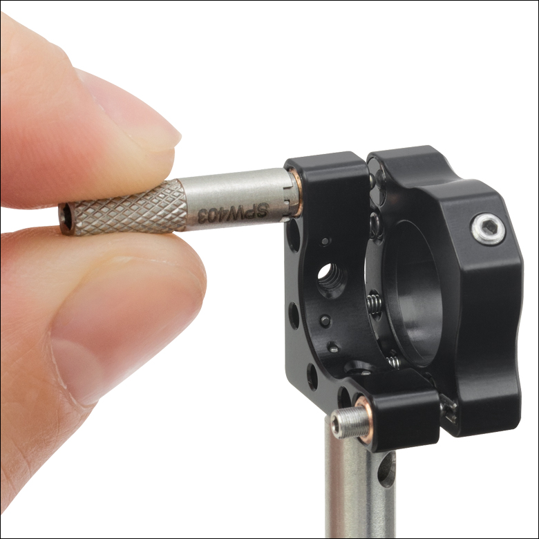
Click to Enlarge
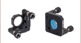
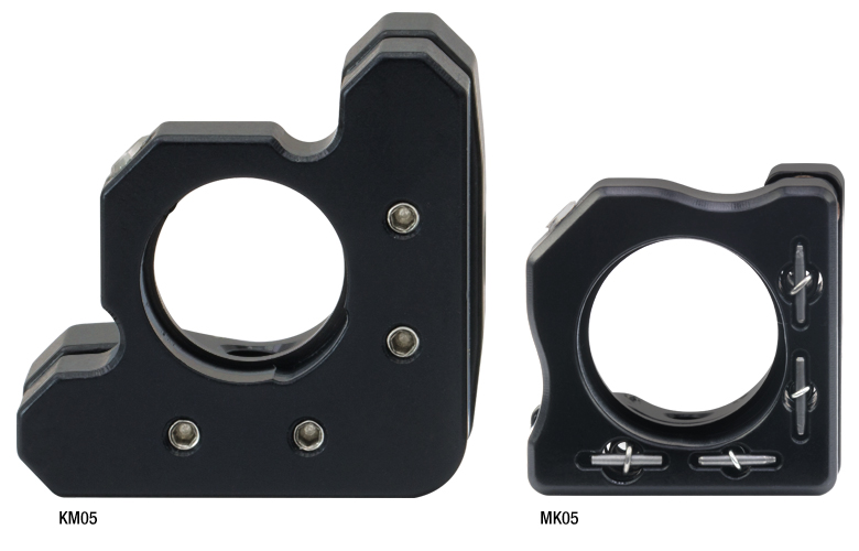
Ø12 mm~Ø12.7 mm(Ø1/2インチ)用キネマティックミラーマウントKM05(/M)とMK05(/M)のサイズの比較。
- 厚さ3.05 mm以上のØ12.5 mm~Ø12.7 mm(Ø1/2インチ)光学素子の取り付けが可能
- コンパクトな設置面積:20.0 mm x 13.2 mm(公称値)
- 角度範囲:±4°
- 分解能:2つのM2.5 x 0.20アジャスタは、1回転につき13.4 mrad(0.76°)の調整が可能
- 2つのM3取付け穴により右手系、左手系のどちらも構成可能
ミニシリーズキネマティックミラーマウントMK05/Mは、省スペースが要求されるオプトメカニクスのセットアップで、Ø12.5 mm~Ø12.7 mm(Ø1/2インチ)の光学素子を取り付けられるように設計されています。MK7/MおよびMK10/Mと同様に、こちらの2アジャスタ付きマウントの設置面積は20.0 mm x 13.2 mm(公称値)で、当社のキネマティックマウントの中では最小です。右の写真でご覧いただけるように、Ø12 mm~Ø12.7 mm(Ø1/2インチ)用キネマティックミラーマウントKM05(/M)と比べて大幅に小型化されています。
ミラーは、先端がナイロン製の固定ネジと2重穴との組合せで、3点支持で固定されます。先端がナイロン製の止めネジ(セットスクリュ)と2個のM2.5 x 0.20アジャスターネジのどちらにも、1.3 mm(0.050インチ)六角レンチ(付属しておりません)が使用可能です。当社では調整が簡単に行えるよう、つまみネジ型の0.050インチ(1.3 mm)六角レンチをお勧めしております(下記参照)。右の写真でご覧いただけるようにアジャスターネジを任意の位置で固定したり、ハードストップを構成したりするために、固定用カラーとスパナレンチもご用意しております。
右手系、左手系のどちらも構成できるよう、マウントにはM3取付け穴が90°の位置に2つ付いており、当社のØ6 mmミニシリーズポストに取り付けられます。Ø6 mmポストは、ミニシリーズポストホルダを用いることで、ミニシリーズブレッドボードに取り付けることができます。
光学素子用")
 ズーム
ズーム
Click to Enlarge
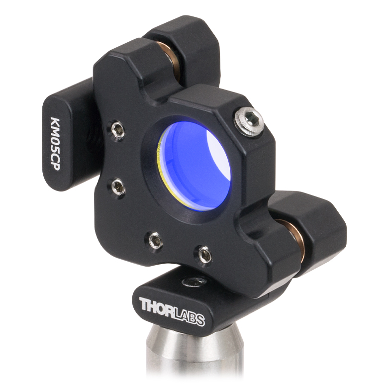
マウントKM05CP(/M)を用いると光学素子の前面をポストの中心軸上に設置できます。
Click to Enlarge
マウントKM05CP(/M)を用いると光学素子の前面をポストの中心軸上に設置できます。
- 2重穴構造の取付けセルに、ナイロンチップ付き止めネジで厚さ1.78 mm以上のØ12 mm~Ø12.7 mm(Ø1/2インチ)光学素子の取付けが可能
- 2種類の方式をご用意
- KM05/M:ミラーを前面から取り付けるタイプ
- KM05CP/M:ミラーを背面から取り付けるタイプ。ミラーの前面がポストの中心軸上に配置されるためビームのアライメントが容易
- 角度調整範囲:±4°
- 分解能:2つの3/16"-100アジャスタは、1回転に付き13 mrad (0.75°)の調整が可能
- 2つのM4取付けネジ穴のどちらを用いるかによって、右手系または左手系の選択が可能
2つのM4取付けネジ穴のどちらを用いるかによって、右手系または左手系の選択が可能 キネマティックミラーマウントKM05/MおよびKM05CP/Mには、厚さ1.78 mm以上のØ12 mm~Ø12.7 mm(Ø1/2インチ)光学素子を取り付けることができます。先端がナイロン製の止めネジ(交換品型番SS8N013)と、2重穴によって形成される2つの接触線とでミラーを固定します。2つの3/16"-100アクチュエータでは、意図しない動作を防止するために六角ソケットを使用しており、それらは2 mm(5/64インチ)つまみネジ型六角レンチ(下記参照)を用いて操作できます。各マウントは、M4の2つの取付けネジ穴のうちの1つを用いて、Ø12 mm、Ø12.7 mm(Ø1/2インチ)ポストまたはØ25 mmのポストに取り付けることができます。ネジ穴を選択することで、アジャスタの向きを右手系にも左手系にも配置できます。
ミラーを前面から取り付けるタイプのマウント
標準型のキネマティックマウントKM05/Mには、ミラーを前面から取り付けるタイプのセルが付いており、光学素子前面からポストの取付け穴までの距離は光学素子の厚さに依存します。マウントKM05/Mでは、ミラーの中心はポストから14.7 mm上側に配置されます。また、マウントKM05/Mに取り付けられた厚さ6 mmのミラーの前面を、ポストの中心軸上に配置するためのセンタリングプレートKCP05/Mもご用意しています。
ミラーを背面から取り付けるタイプのポストセンタリングプレート付きマウント
キネマティックミラーマウントKM05CP/Mは、光学素子の前面が取り付けたポストの中心軸上に配置されるように設計されています。そのため取り付けたポストを回転させたときにビームのウォークオフが発生せず、従ってポストの回転による粗い回転調整が可能です。このマウントをテーブルの穴の上に設置するか、またはテーブルに直接取り付けることで、45°で入射するビームをテーブルの穴配列に簡単にアライメントすることができます。マウントKM05CP/Mでは、ポストの取付け構造によりミラーの中心はポストの21.1 mm上側に配置されます。
光学素子用")
 ズーム
ズーム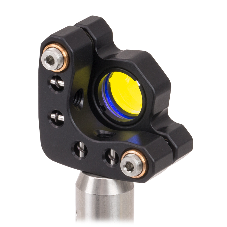
- SM05ネジ付き光学セルに2つの固定リングを使用して、厚さ4 mmまでのØ12 mm~Ø12.7 mm(Ø1/2インチ)光学素子を固定
- 角度調整範囲:±4°
- 分解能:2つの3/16"-100アジャスタは、1回転に付き13 mrad (0.75°)の調整が可能
- 2つのM4取付けネジ穴のどちらを用いるかによって、右手系または左手系の選択が可能
- SM05ネジを用いてØ12 mm~Ø12.7 mm(Ø1/2インチ)レンズチューブの取付けが可能
SM05ネジ付きキネマティックミラーマウントKM05T/Mは、薄型(厚さ4 mmまで)のØ12 mm~Ø12.7 mm(Ø1/2インチ)光学素子用に設計されています。光学素子は、付属する2つのSM05RRネジ付き固定リングSM05RRを用いて取付け穴に固定します。取付けの際は、スパナレンチSPW603またはSPW603Lをご使用いただけます。このマウントには、Ø12 mm~Ø12.7 mm(Ø1/2インチ)レンズチューブなどのSM05ネジ付きコンポーネントも取り付けられます。KM05T/Mは、2つのM4取付けネジ穴のうちの1つを用いてポストに取り付けることができます。ネジ穴の選択により、右手系または左手系のどちらにも構成できます。 また、アダプタKMCP(/M)を使用すれば、マウントKM05/Mでも光学素子の前面をポストの中心軸上に配置することができます。
さらに、適切なアダプタを使用すれば、SMネジ付きキネマティックマウントにファイバーコリメータなどの円筒形コンポーネントを取り付けることもできます。
光学素子用")
 ズーム
ズーム| KM100 Mount & Mirror Kits | ||
|---|---|---|
| Kit Item # | Mirror Item # | Wavelength Range |
| KM100-E01 | BB1-E01 | 350 - 400 nm |
| KM100-E02 | BB1-E02 | 400 - 750 nm |
| KM100-E03 | BB1-E03 | 750 - 1100 nm |
| KM100-E04 | BB1-E04 | 1280 - 1600 nm |
- 2重穴構造の取付けセルに、ナイロンチップ付き止めネジで厚さ3 mm以上のØ25 mm~Ø25.4 mm(Ø1インチ)光学素子の取付けが可能
- 2種類の方式をご用意
- KM100:ミラーを前面から取り付けるタイプ
- KM100CP/M:ミラーを背面から取り付けるタイプ。ミラーの前面がポストの中心軸上に配置されるためビームアライメントが容易
- 角度調整範囲:±4°
- 分解能:2つの1/4"-80アジャスタは、1回転につき8 mrad (0.5°)の調整が可能
- 2つの取付け穴のどちらを用いるかによって、右手系または左手系の選択が可能
- KM100:M4用ザグリ穴
- KM100CP/M:M4ネジ穴
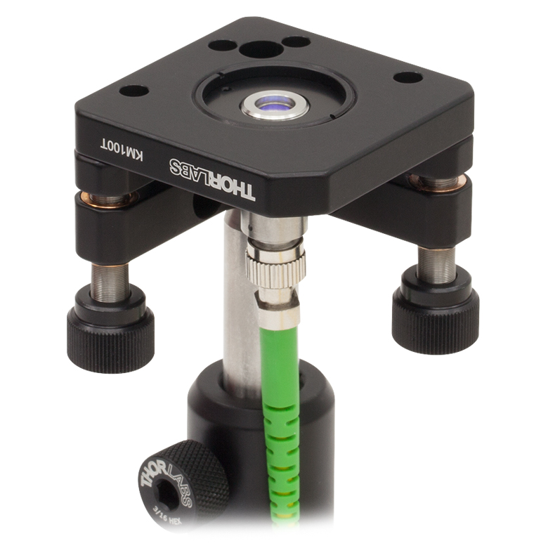
キネマティックミラーマウントKM100およびKM100CP/Mには、厚さ3 mm以上のØ25 mm~Ø25.4 mm(Ø1インチ)光学素子を取り付けることができます。マウントKM100については、4種類の広帯域誘電体ミラーの中から1種類をお選びいただいて付属品とするセット品もご用意しています(詳細は右の表をご覧ください)。先端がナイロン製の止めネジ(交換品型番SS8N013)と、2重穴によって形成される2つの接触線とでミラーを固定します。2つの1/4"-80アクチュエータには2.0 mmの六角ソケットが付いており、ノブを付けたままでも取り外した状態でも操作可能です。また青銅製止めナットLN2580 (別売り)を使用して、位置決め確定後にアジャスタを固定することができます。
Click to Enlarge
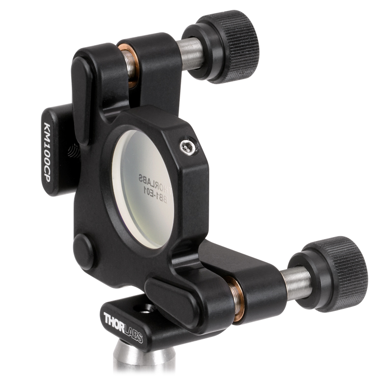
KM100CP(/M)を用いると光学素子の前面がポストの中心軸上に配置されます。
Click to Enlarge
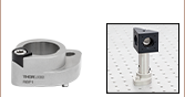
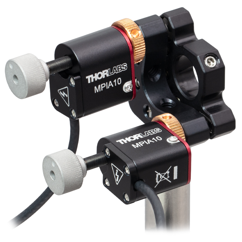
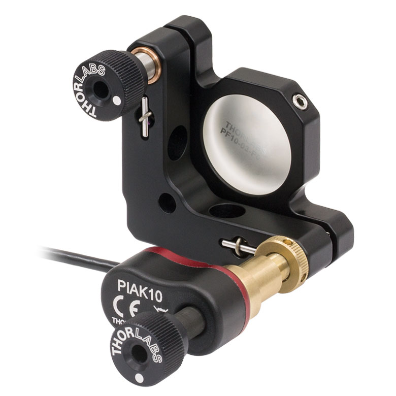
ピエゾ慣性アクチュエータPIAK10を取り付けたマウントKM100

Click to Enlarge
アジャスターノブは取外し可能です。
ミラーを前面から取り付けるタイプのマウント
KM100は、当社のØ25 mm~Ø25.4 mm(Ø1インチ)光学素子用ミラーマウントの中でも人気の高い製品です。このマウントは、2つの取付け用ザグリ穴(M4用)のうちの1つを用いて、Ø12 mm、Ø12.7 mm(Ø1/2インチ)ポストまたはØ25 mmポストのポストに取り付けることができます。取付け穴を選択することで、アジャスタの向きを右手系にも左手系にも配置できます。KM100については、4種類の広帯域誘電体ミラーのうちの1種類を付属品とするセット品も、標準品としてご用意しています(詳細は右の表をご覧ください)。
マウントKM100では、ミラーの中心はポストから25.4 mm上側に配置されます。また、マウントKM100に取り付けられた厚さ6 mmのミラーの前面を、ポストの中心軸上に配置するためのセンタリングプレートKCP1/Mもご用意しております。
ミラーを背面から取り付けるタイプのポストセンタリングプレート付きマウント
ミラーマウントKM100CP/Mは、ミラーの前面が取り付けたポストの中心軸上に配置されるように設計されています。そのため取り付けたポストを回転させたときにビームのウォークオフが発生せず、従ってポストの回転による粗い回転調整が可能です。このマウントは、2つの取付け用M4タップ穴のうちの1つを用いて、Ø12 mm、Ø12.7 mm(Ø1/2インチ)ポストまたはØ25 mmのポストに取り付けることができます。タップ穴を選択することで、アジャスタの向きを右手系にも左手系にも配置できます。ミラーの前面をブレッドボードの取付け穴の真上に配置できれば、45°で入射するビームをテーブルの穴の配列に容易にアライメントできます。
マウントKM100CP/Mでは、ポストの取付け構造によりミラーの中心はポストの31.8 mm上側に配置されます。
光学素子用")
 ズーム
ズーム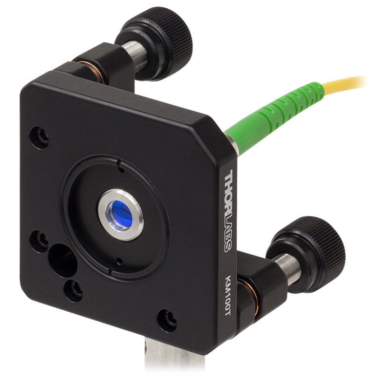

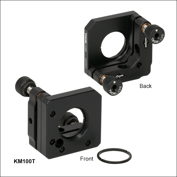
- SM1ネジ付き光学セルに2つの固定リングを使用して、厚さ3.5 mmまでのØ25 mm~Ø25.4 mm(Ø1インチ)光学素子を固定
- 角度調整範囲: ±4°
- 分解能:2つの1/4"-80アジャスタは、1回転につき8 mrad (0.5°)の調整が可能
- 3つのM4用ザグリ貫通穴の何れを用いるかによって、取付けの構成を左手系、右手系、または上向きの3種類から選択可能
- SM1ネジを用いてØ25 mm~Ø25.4 mm(Ø1インチ)レンズチューブの取付けが可能
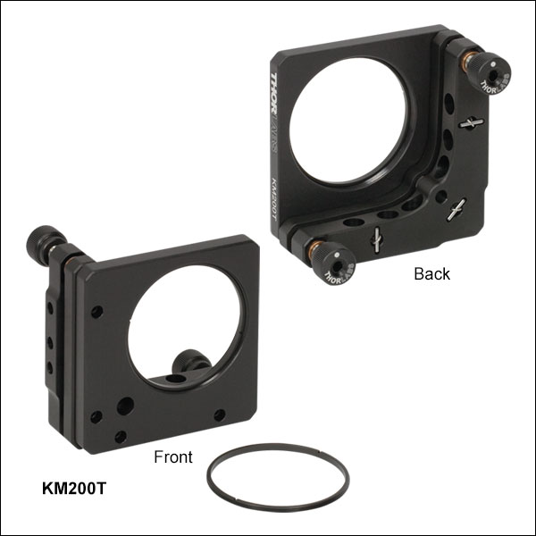
SM1ネジ付きキネマティックミラーマウントKM100Tは、薄型(厚さ3.5 mmまで)のØ25 mm~Ø25.4 mm(Ø1インチ)光学素子用に設計されています。光学素子は、付属する2つのSM1ネジ付き固定リングSM1RRを用いて取付け穴に固定します。取付けの際は、スパナレンチSPW602をご使用いただけます。このマウントには、Ø25 mm~Ø25.4 mm(Ø1インチ)レンズチューブなどのSM1ネジ付きコンポーネントも取り付けられます。
マウントKM100Tは、M4用ザグリ穴を介してØ12 mmおよびØ12.7 mmポストに取り付けられます。その際、右手系、左手系、または上向きの3種類の取付け方法から選択が可能です(右の写真参照)。2つの1/4"-80アクチュエータには2.0 mmの六角ソケットが付いており、ノブを付けたままでも取り外した状態でも操作可能です。また青銅製止めナットLN2580(別売り)を使用して、位置決め確定後にアジャスタを固定することができます。 さらに、アダプタKMCP/Mを使用すれば、マウントKM100Tでも光学素子の前面をポストの中心軸上に配置することができます。
SMネジ付きキネマティックマウントは、AD11Fのようなアダプタを使用することで、ファイバーコリメータなどの円筒形コンポーネントを取り付けることもできます(上の写真参照)。
光学素子用")
 ズーム
ズーム| KM200 Mount & Mirror Kits | ||
|---|---|---|
| Kit Item # | Mirror Item # | Wavelength Range |
| KM200-E02 | BB2-E02 | 400 - 750 nm |
| KM200-E03 | BB2-E03 | 750 - 1100 nm |


Click to Enlarge
KM200CP(/M)を用いると光学素子の前面がポスト中心軸上に配置されます。
- 2重穴構造のセルに、ナイロンチップ付き止めネジで厚さ4 mm以上のØ50 mm~Ø50.8 mm(Ø2インチ)光学素子の取付けが可能
- 2種類の方式をご用意:
- KM200:ミラーを前面から取り付けるタイプ
- KM200CP(/M):ミラーを背面から取り付けるタイプ。ミラーの前面がポストの中心軸上に配置されるためビームアライメントが容易
- 角度調整範囲:±3°
- 分解能:2つの1/4"-80アジャスタは、1回転につき5 mrad (0.3°)の調整が可能
- 2つの取付け穴のどちらを用いるかによって、右手系または左手系の選択が可能
- KM200:M4用ザグリ穴
- KM200CP(/M):M4ネジ穴
キネマティックミラーマウントKM200およびKM200CP/Mには、厚さ4 mm以上のØ50 mm~Ø50.8 mm(Ø2インチ)光学素子を取り付けることができます。マウントKM200については、2種類の広帯域誘電体ミラーの中から1種類をお選びいただいて付属品とするセット品もご用意しています(詳細は右の表をご覧ください)。先端がナイロン製の止めネジ(交換品型番SS8N013)と、2重穴によって形成される2つの接触線とでミラーを固定します。2つの1/4"-80アクチュエータには2.0 mmの六角ソケットが付いており、ノブを付けたままでも取り外した状態でも操作可能です。また青銅製止めナットLN2580 (別売り)を使用して、位置決め確定後にアジャスタを固定することができます。
ミラーを前面から取り付けるタイプのマウント
KM200は、当社のØ50 mm~Ø50.8 mm(Ø2インチ)光学素子用ミラーマウントの中でも人気の高い製品です。このマウントは、2つの取付け用ザグリ穴(M4用)のうちの1つを用いて、Ø12 mm、Ø12.7 mm(Ø1/2インチ)ポストまたはØ25 mmのポストに取り付けることができます。取付け穴を選択することで、アジャスタの向きを右手系にも左手系にも配置できます。KM200については、2種類の広帯域誘電体ミラーのうちの1種類を付属品とするセット品も、標準品としてご用意しています(詳細は右の表をご覧ください)。
マウントKM200では、ミラーの中心はポストの39.6 mm上側に配置されます。また、マウントKM200に取り付けられた厚さ12 mmのミラーの前面を、ポストの中心軸上に配置するためのセンタリングプレートKCP2/Mもご用意しております。
ミラーを背面から取り付けるタイプのポストセンタリングプレート付きマウント
ミラーマウントKM200CP/Mは、ミラーの前面が取り付けたポストの中心軸上に配置されるように設計されています。そのため取り付けたポストを回転させたときにビームのウォークオフが発生せず、従ってポストの回転による粗い回転調整が可能です。各マウントは、2つの取付け用M4タップ穴のうちの1つを用いて、Ø12 mm、Ø12.7 mm(Ø1/2インチ)ポストまたはØ25 mmのポストに取り付けることができます。タップ穴を選択することで、アジャスタの向きを右手系にも左手系にも配置できます。ミラーの前面をブレッドボードの取付け穴の真上に配置できれば、45°で入射するビームをテーブルの穴の配列に容易にアライメントできます。
マウントKM200CP/Mでは、ポストの取付け構造によりミラーの中心がポストの47.0 mm上側に配置されます。
光学素子用")
 ズーム
ズーム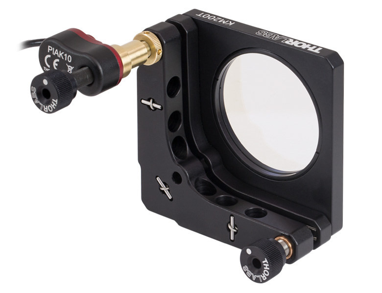
- SM2ネジ付き光学セルに2つの固定リングを使用して、厚さ2.5 mmまでのØ50 mm~Ø50.8 mm(Ø2インチ)光学素子を固定
- 角度調整範囲:±3°
- 分解能:2つの1/4"-80アジャスタは、1回転につき5 mrad (0.3°)の調整が可能
- 7つのM4ザグリ貫通穴によって左手、右手、あるいは上向きに設置可能
- SM2ネジによってØ50 mm~Ø50.8 mm(Ø2インチ)レンズチューブに対応
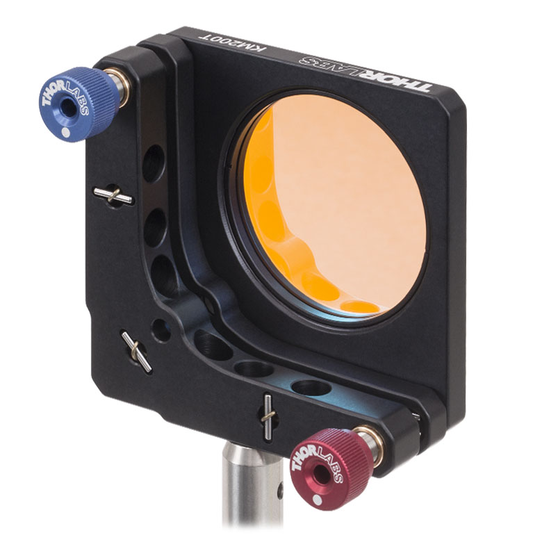
SM2ネジ付きキネマティックミラーマウントKM200Tは、厚さ2.5 mmまでのØ50 mm~Ø50.8 mm(Ø2インチ))薄型光学素子用に設計されています。光学素子は付属する2つのSM2ネジ付き固定リングSM2RRで取付け穴に固定されます。取り付けにはスパナレンチSPW604がご使用いただけます。こちらのマウントは、Ø50 mm~Ø50.8 mm(Ø2インチ)レンズチューブなどのSM2ネジ付きコンポーネントにも対応しています。
マウントKM200TはM4ザグリ穴からØ12 mmおよびØ12.7 mm(Ø1/2インチ)ポストに取り付け可能です。また、右手、左手または上向き設置できます(右の写真参照)。2つの1/4"-80アクチュエータには2.0 mmの六角ソケットが使われており、ノブを付けたままでも取り外した状態でも調整可能です。また青銅製止めナットLN2580(別売り)を使用して、位置決め確定後にアジャスタを固定することができます。 さらに、アダプタKMCP/Mを使用すれば、マウントKM200Tでも光学素子の前面をポストの中心軸上に配置することができます。

 ズーム
ズーム

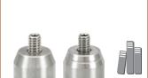
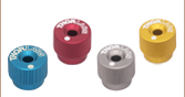
- 1.3 mm(0.050インチ)または2 mm(5/64インチ)の六角レンチで操作するアクチュエータの操作に便利
- 赤色アルマイト加工の調整ノブ、六角レンチのサイズが刻印
- 六角ビットは交換可能
- 4個入りパックで販売
つまみネジ型六角レンチをお使いいただくと、六角レンチで操作するアクチュエータ、キャップスクリュ、止めネジ(セットスクリュ)を素早く、かつスペースをとらずに調整することが可能です。ボール(六角)ドライバとは異なり、調整の合間もネジの六角穴に取り付けたままにしておけるので便利です。
1.3 mm(0.050インチ)つまみネジ型六角レンチHKTS-050は上記のMKミニシリーズマウントに対応し、2 mm(5/64インチ)つまみネジ型六角レンチHKTS-5/64はKMシリーズのマウントに対応しています。六角ビットは交換可能で、#8-32止めネジを2 mm(5/64インチ)六角レンチで締めて取り付けます。六角ビットの先端がつぶれたときは、逆向きにして再利用できます。交換用の六角ビットが必要な場合には、当社までお問い合せください。
つまみネジ型六角レンチとしては、1.3 mm~5 mmと5/64インチ~3/16インチのサイズをご用意しております。