 Products Home
1軸走査型ガルバノシステムVantagePro®
- ±15°, ±20°, and ±22.5° Scan Angles and Beam Diameters Up to 45 mm
- Choice of Broadband Protected Silver or Mirror Coatings for 355 and 1064 nm
- Easy to Integrate with OEM Systems
- Analog Control Electronics
Servo Driver Included with
Galvanometer Scanners for
Ø7 or Ø10 mm Beams
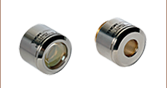
QS10Y-Y3
Vertical Mirror for Ø10 mm Beams, Dielectric Nd:YAG Coating
Servo Driver Included with
Galvanometer Scanners for Ø4 or Ø5 mm and Ø15 to Ø45 mm Beams
QG4X-AG
Horizontal Mirror for Ø4 mm Beams, Protected Silver Coating
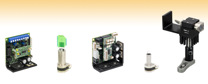
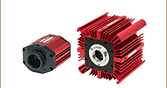
Post-Mounted QS15X-AG Galvo in a QSM2/M Mount with Heat Sink


Please Wait
| Table 1.1 Single-Axis Galvanometer Scanner Selection Guide | |||||
|---|---|---|---|---|---|
| Item # Prefix (X- or Y-Axis) | Mirror Coatingsa | Max Beam Diameter | Position Detector | ||
| -AG | -Y3 | -Y1 | |||
| QG4(X)(Y) | - | 4 mm | Optical | ||
| QG5(X)(Y) | - | 5 mm | |||
| QS7(X)(Y) | 7 mm | ||||
| QS10(X)(Y) | 10 mm | ||||
| QS15(X)(Y) | 15 mm | ||||
| QS20(X)(Y) | 20 mm | ||||
| QS30(X)(Y) | - | 30 mm | Capacitive | ||
| QS45(X)(Y) | - | 45 mm | |||
| Power Supply & Command Cables | |||||

用途
- レーザーマーキング
- Additive Manufacturing(3Dプリント技術)
- レーザ刻印
- レーザ溶接
- 微細加工
- レーザードリル
- レーザーアブレーション、表面加工
- レーザ切断、レーザースクライブ
- レーザ走査型顕微鏡
- レーザ投影
特長
- 可動マグネットモータ設計により高速応答が可能(200~1200 µs)
- 高精密光学式または静電容量式のミラー位置検出(詳細はTable 1.1をご覧ください)
- 3種類のミラーコーティングが選択可能
- 保護膜付き銀コーティング:450 nm~10.6 µm
- Nd:YAGレーザ、第3高調波、355 nm
- Nd:YAGレーザ、1064 nm
- 633 nmのアライメントレーザでも高反射率
- カレントダンピング付きアナログPID制御回路
- 610 mm長の駆動ケーブルが付属
- 電源、コマンドケーブル、電源ケーブルは別売り(下記参照)
- ご要望に合わせて特注コーティングも承ります(詳細は当社までご相談ください)。
カスタム仕様および組み込み用途(OEM用途)
大量注文について
当社では走査型ガルバノミラーシステムのカスタマイズや組み込み用途(OEM用途)に対応いたします。光学素子のサイズやコーティング、特殊なチューニング、マウントやケーブルのカスタマイズを承ります。
標準品がご要望に合わない場合や、まとまった数量をご希望の際は、ぜひ一度当社までご連絡いただき、お客様のご希望に沿ったカスタマイズについてご相談ください。
We look forward to hearing from you!
高速走査型ガルバノミラーシステムVantagePro®は、組み込み用途(OEM用途)またはカスタム仕様のレーザービームステアリング用途向けにご用意しました。ビーム径最大45 mm対応のモデルもご用意しております。各システムにはミラー付き1軸ガルバノモータとドライバーカードが含まれます。寸法と取付部の特長については、下の型番横の赤いアイコン(![]() )をクリックするとご覧いただけます。±15 V電源(オープンフレームまたはエンクローズド)、コマンドケーブル、そしてマウントは別売りです(下記をご参照ください)。 これらがどのガルバノシステムに対応するかについての情報については「電源&ケーブル対応表」タブをご覧ください。
)をクリックするとご覧いただけます。±15 V電源(オープンフレームまたはエンクローズド)、コマンドケーブル、そしてマウントは別売りです(下記をご参照ください)。 これらがどのガルバノシステムに対応するかについての情報については「電源&ケーブル対応表」タブをご覧ください。
サーボドライバを操作するには、ファンクションジェネレータ、またはその他のアナログ電圧出力デバイスをご用意いただく必要があります。ミラーはカスタム仕様の保護膜付き広帯域銀コーティング、355 nm用反射コーティング、1064 nm用反射コーティングの3種類のコーティングでご用意しています(Table 1.1参照)。ご要望に合わせてカスタムコーティングも承ります。詳細は当社までお問い合わせください。当社ではQSシリーズガルバノスキャンヘッドを使用する2軸システムやスキャナーヘッドとコントローラが揃ったシステムをご用意しています。
サーボドライバーボード
これらの閉ループのサーボドライバ回路は、モータ内部の位置検出システムからの信号を処理し、指定した位置までミラーを回転させるのに必要な駆動電圧を供給します。高帯域幅により、アナログコマンド波形に高速かつ高確度で追随します。
どちらのドライバも高性能のための高度なカレントダンパー付きPIDサーボドライバ回路を備えています。ドライバには確度を向上させるためにSN比(信号対雑音比)を最大化する低ノイズコンポーネントと、温度変動の影響を少なくする低ドリフトコンポーネントが内蔵されています。それぞれのミラーとガルバノの組み合わせに対してノッチフィルタが選択、調整されているため、システム帯域幅が最大化され、より高速で高確度な走査が実現します。これらのシステムはステップ走査、ベクタ走査(レーザーマーキングなど)、ラスタ走査(3Dプリンタ、レーザ走査顕微鏡)などの用途に適しています。
サーボはすべての用途において高速、そして精密な位置決め用の最適化されています。ビーム径が4 mmまたは5 mm、あるいは最大ビーム径が15 mm以上のスキャナ用のサーボには、追加でデュアル出力のパワーアンプが付いているため、性能を損なうことなくより大きなモータに必要な電源供給が可能です。サーボドライバ回路にはソフトスタート・ストップの動作、AGC開回路フェールセーフ、および過不足電圧保護機能が備わっています。ステータスLEDは、サーボのステータスと故障の状態を示し、診断ポートにより位置、速度、誤差、電流情報が提供されます。ドライバ、ガルバノ、ミラーのセットはそれぞれ個別検査され、仕様を満たすよう調整されています。ガルバノのそれぞれのシリアルナンバは対応するドライバーボードにも記されています。なお、X/Yドライバはそれぞれのサーボ向けで、ドライバ同士は交換できません。
| Galvanometer Scanner Specs | |||||||||
|---|---|---|---|---|---|---|---|---|---|
| Item # Prefix | QG4X QG4Y | QG5X QG5Y | QS7X QS7Y | QS10X QS10Y | QS15X QS15Y | QS20X QS20Y | QS30X QS30Y | QS45X QS45Y | |
| Max Beam Diameter | 4 mm | 5 mm | 7 mm | 10 mm | 15 mm | 20 mm | 30 mm | 45 mm | |
| Mirror Substrate | Fused Silica | Silicon Carbide | |||||||
| Step Response Time (0.4° Opticala) | 200 µs ± 5%b | 250 µs ± 5%b | 250 µs | 350 µs | 600 µs | 650 µs | 1200 µs | 1200 µs | |
| Mechanical and Electrical Specs | |||||||||
| Rated Excursiona | ±15° | ±20° | ±22.5° | ||||||
| Rotor Inertial Load | Recommended | 0.018 g·cm2 | 0.17 g·cm2 | 1.8 g·cm2 | 5.1 g·cm2 | ||||
| Max | 0.09 g·cm2 | 0.85 g·cm2 | 9 g·cm2 | 25 g·cm2 | |||||
| Torque Constant | 29 300 dyne·cm/A | 40 000 dyne·cm/A | 180 000 dyne·cm/A | 280 000 dyne·cm/A | |||||
| Coil Resistance | 4.7 Ω | 1.3 Ω | 3.0 Ω | 5.8 Ω | |||||
| Coil Inductance | 110 µH @ 1 kHz | 76 µH @ 1 kHz | 530 µH @ 1 kHz | 450 µH @ 1 kHz | |||||
| Position Detector | |||||||||
| Type | Optical | Capacitive | |||||||
| Linearity @ Full Excursion | ≥99.88% | 99.8% @ ±20° | >99.9% | ||||||
| Gain Drift | <30 ppm/°C | 50 ppm/°C | 50 ppm/°C | ||||||
| Offset Drift | <20 µrad/°C | 30 µrad/°C | 40 µrad/°C | ||||||
| Repeatability | ≤20 µrad | 10 µrad | 15 µrad | ||||||
| Output Signal (Typ.) | Differential Modea | 6 µA/° | 7.1 µA/° | 40 µA/° | |||||
| Common Mode | 300 µA | 385 µA | 2100 µA | ||||||
| Supply Current | 15 - 30 mA | 30 - 40 mA | 10 - 20 mA | ||||||
| General Specs | |||||||||
| Operating Temperature | 0 to 40 °C (Non-Condensing) | ||||||||
| Storage Temperature | -10 to 50 °C | ||||||||
| Servo Shaft Size | Ø9.47 mm x 35.7 mm | Ø14 mm x 26.3 mm | Ø22 mm x 50 mm | Ø30.5 mm x 30 mm | |||||
| Mass (Galvo Only) | 23 g | 36 g | 128 g | 306 g | |||||
| Mirror Coating Specs | |||
|---|---|---|---|
| Item # Suffix | -AG | -Y3 | -Y1 |
| Coating Type | Custom Protected Silver | Hard Dielectric for Nd:YAG Laser 3rd Harmonic | Hard Dielectric for Nd:YAG Laser Fundamental |
| Absolute Reflectance | ≥92% (450 - 500 nm) ≥94.5% (500 - 2000 nm) ≥98% (2 - 10.6 µm) | ≥99% (355 nm) ≥80% (633 nm) | ≥98% (1064 nm) ≥80% (633 nm) |
| Surface Quality (Scratch-Dig) | 40-20 | 20-10 | 40-20 |
| Servo Amplifier Specsa | ||||
|---|---|---|---|---|
| Item # Prefix | QG4(X)(Y) | QG5(X)(Y) | QS7(X)(Y) QS10(X)(Y) | QS15(X)(Y) QS20(X)(Y) QS30(X)(Y) QS45(X)(Y) |
| Inputs | ||||
| Command Input Range | ±10 V | ±5 V | ||
| Position Input Scale Factorb | 0.67 V/° | 0.50 V/° | 0.22 V/° | |
| Command Input Impedance | 20 kΩ ± 1% (Differential) 10 kΩ ± 1% (Single Ended) | 400 kΩ (Differential) 200 kΩ (Single Ended) | 20 kΩ ± 1% (Differential) 10 kΩ ± 1% (Single Ended) | |
| Position Offset Range | ±0.25 V | |||
| External Enable | See Footnote c for Details | TTL (Low: Disable Drive) | See Footnote c for Details | |
| Diagnostic Outputs | ||||
| Servo Ready | 12 V | TTL | 12 V | |
| Positionb | 0.33 V/° | 0.50 V/° | 0.22 V/° | |
| Position Errorb | 0.33V/° | 0.50 V/° | 0.22 V/° | |
| Velocity | Analog (Reference Only) | |||
| AGC Voltage | Analog (DC) | |||
| Coil Current | 1 V/A | |||
| Analog Output Impedance | 1 kΩ ± 1% (For All Outputs) | Unbuffered | 1 kΩ ± 1% (For All Outputs) | |
| Power Supply (Not Included) | ||||
| Input Voltage | ±15 to ±24 VDC < 100 mV Ripple < 0.5% DC to 30 MHz Noise | ±15 VDC < 100 mV Ripple < 0.5% DC to 30 MHz Noise | ±15 to ±24 VDC < 100 mV Ripple < 0.5% DC to 30 MHz Noise | |
| Maximum Drive Current Limit | 2 A (RMS); 6 A (Peak) | 3 A (RMS); 10 A (Peak) | 4 A (RMS); 10 A (Peak) | |
| Quiescent Current | 220 mA (Servo Enabled, Galvo at Rest) | |||
| Gain Drift | Up to 20 ppm/°C | |||
| Offset Drift | Up to 26 µrad/°C | Up to 30 µrad/°C | ||
| General Specs | ||||
| Operating Temperature | 0 to 45 °C (With Appropriate Cooling) | |||
| Storage Temperature | -10 to 60 °C | |||
| Dimensions | 2.38" x 2.13" x 1.06" (60.5 mm x 54.1 mm x 27.0 mm) | 2.38" x 2.22" x 1.06" (60.5 mm x 56.4 mm x 27.0 mm) | 2.38" x 2.13" x 1.06" (60.5 mm x 54.1 mm x 27.0 mm) | |
| Mass (Weight) | 74 g (2.6 oz) | 49 g (1.7 oz) | 74 g (2.6 oz) | |

ガルバノモータ/ミラーアセンブリ
こちらのシステムは、シャフト上に光学ミラーが取り付けられたガルバノスキャナがベースの走査型モータと制御ボードに位置フィードバックを送るディテクタで構成されています。QSおよびQGシリーズのガルバノモータは、固定磁石や回転式コイル設計ではなく可動磁石設計を採用し、高速応答と高い共振周波数をご提供できます。ミラー位置は、モータ筐体内にある光学または静電容量式センシングシステムを使ってエンコードされます。
回転シャフトの角加速度が大きいため、ミラーのサイズや形状、慣性モーメントは高性能ガルバノシステム設計において重要な要素となります。さらに、ミラーは大きな加速度に追従する時でも形状歪の無い状態(フラット性)を維持しなければいけません。当社のシステムでは、モータの特性に合わせてシステムの性能を最大限に高めるために、これらの要素は全て最適化されています。
ミラーはフレクシャークランプを用いてモータ/ミラーアセンブリに固定されます。光学マウントの位置は出荷時に設定済みですので、お客様側で変更はできません。
システムの操作
サーボドライバは、DC 電源、ガルバノモータ、入力電源(モニタ接続はオプションです)に接続する必要があります。連続走査用途では、正弦波出力ができるファンクションジェネレータによりガルバノミラーのすべての角度を走査することが可能です。さらに複雑なパターンを走査するには、DAQカードなどプログラム可能な電圧源を使用します。移動軌跡をお客様が生成する場合、なめらかな加速プロファイルとなるようにしてください。可能であれば、無制御のステップは避けてください。なお、これらのシステムには電源(別売り、下記参照)、ファンクションジェネレータあるいはDAQカードは付属しませんのでご注意ください。下記のドライバは、入力電圧とミラー位置(角度)の比が0.22 V/° (QSシリーズ)、0.5 V/° (QG5シリーズ)、または0.67 V/° (QG4シリーズ)、そして入力電圧が±5VDC (QSシリーズ)または±10VDC (QGシリーズ)になるように工場出荷時に設定されています。0.44 V/° と±10 VDCに設定されているドライバもご要望によりご提供いたします。当社までご連絡ください。制御回路には、ミラーの位置のトラッキングに必要なモニタ出力機能も付いています。さらに、モータに供給される駆動電流に比例した電圧と、コマンド指定した位置とミラーの実際の位置との差が、制御回路によって供給されます。
閉ループミラーの位置決め
ミラーの角度方向(位置)は、ガルバノ筐体内部に組み込まれた光学または静電容量式センシングシステムを使って測定されています。 それによりガルバノミラーの方向を閉ループ動作で安定化させることが可能になります。
Table 4.1ではガルバノシステムを動作するために必要な電源とケーブルを示しています。ガルバノシステムを選択後、対応する電源とケーブルセットをご確認ください。 オープンフレーム電源ではケーブルをシステムにはんだ付けする必要があります。筐体付き電源ではケーブルを直接システムに接続することが可能です。 システムには、別途コントローラが必要です(付属しておりません)。
| Table 4.1 Galvo Compatability | |||
|---|---|---|---|
| Galvo | Compatible Power Supply (Supports up to Two Axes) | Compatible Cable Set (Choose One Per Axis) | Compatible Mount (Optional) |
| QG4 or QG5 | GPWR15 Open Frame Power Supplya | CBLS3F | QSM4(/M) |
| GPS011 Series Enclosed Power Supplyb | CBLS3P | ||
| QS7 or QS10 | GPWR15 Open Frame Power Supplya | CBLS2F | QSM1(/M) |
| GPS011 Series Enclosed Power Supplyb | CBLS2P | ||
| QS15 or QS20 | GPWR15 Open Frame Power Supplya | CBLS3F | QSM2(/M) |
| GPS011 Series Enclosed Power Supplyb | CBLS3P | ||
| QS30 or QS45 | GPWR15 Open Frame Power Supplya | CBLS3F | QSM3(/M) |
1軸走査型ガルバノシステムには下記が含まれます。

Click to Enlarge
Figure 5.1 ガルバノシステムQG4およびQG5シリーズ
ガルバノシステムQG4、QG5、QS15、QS20、QS30、QS45シリーズ
- ミラー付きガルバノモータ
- Class 1サーボアンプ
- 61 cmケーブルアセンブリ(モータとサーボアンプを接続)
- コネクターキット(QG4/5シリーズサーボアンプのマニュアル、または QS15/20/30/45シリーズサーボアンプのマニュアル参照)
ガルバノシステムQS7、QS10シリーズ
- ミラー付きガルバノモータ
- Class 0サーボアンプ
- 61 cmケーブルアセンブリ(モータとサーボアンプを接続)
- コネクターキット(QS7/10シリーズサーボアンプのマニュアル参照)
| Posted Comments: | |
Ulrich Leischner
(posted 2025-02-17 14:20:22.297) What is the size of the mirror? is the "Max 45mm diameter" most likely for 45°-orientation, and 90° reflection, right? which angel is possible for deflection for a full 45mm beam diameter and 90° deflection, until beam truncation will start? cdolbashian
(posted 2025-02-26 04:53:24.0) Thank you for reaching out to us with this inquiry. While we do state this as a 45mm mirror, in actuality it only has a clear aperture of 40mm, and we will be updating the presentation in the near future. Now, regarding the revised question "what is the max angle which will not clip a 40mm beam?". The length of the mirror is 72.5mm, and the nominal zero-position is 45° AOI. when the angle is reduced to ~33°, the projected size of the mirror is ~40mm. In this sense, you can use the full mechanical excursion of the galvo +/-11.25°. Hazen Babcock
(posted 2024-07-31 13:27:15.137) Do you provide STEP files for the servo driver boards? cdolbashian
(posted 2024-08-14 12:32:42.0) Thank you for reaching out to us with this inquiry. We can indeed provide such files. Additionally, we have mechanical drawings in the Servo manual, which has relevant dimensions. I have contacted you directly to follow up with these STEP files. 常胜 李
(posted 2024-07-23 01:57:16.43) 有详细的振镜电机测试报告(质检报告)吗?包含重复定位精度、线性度、温漂等参数 cdolbashian
(posted 2024-07-29 10:55:25.0) Thank you for reaching out to us with this inquiry. You asked the following: Do you have a detailed test report (QC report) for the galvanometer motor? Include parameters such as repeatability, linearity, temperature drift, etc.
This is likely something we can get for you, as each galvo is tested for these types of parameters. I have contacted you directly to inquire about which specific tests you need, and whether or not we can provide all of them. cdolbashian
(posted 2024-06-04 02:02:55.0) Thank you for reaching out to us with the following inquiry: Hello, I bought the QS20X-AG galvanometer. I would like to ask, if I want to place it directly on the optical table vertically and rotate it around the vertical z-axis during work, what kind of mounting base do I need? I have reached out to you directly to recommend some parts which would potentially work for your application. user
(posted 2024-06-03 10:56:01.51) Can you help to mount and tune a custom optics on the QS20X-AG rotor? Hongrae Kim
(posted 2024-04-29 13:28:32.56) I'm using a galvo mirror from Thorlabs, QS7X-AG, and I found that QS7X-AG has a slight vibration about +- 10 micro radians even when at rest.
I found that the stated repeatability for this model is 10 micro radians according to Thorlabs website.(https://www.thorlabs.com/newgrouppage9.cfm?objectgroup_id=14115&pn=QS7X-AG#14129)
Does the term "repeatability" mean that its vibration is about 10 micro radians?
And is 10 micro radians a minimum value for "repeatability"? (My galvo's vibration is about 20 micro radians. So I wonder whether this value is within an acceptable range...) cdolbashian
(posted 2024-05-06 10:49:41.0) Thank you for reaching out to us with this inquiry. I would not expect you to see such vibrations (corresponding to uV of signal). When we measure stable vibrations in the lab, our measured values are consistently lower. Perhaps this has to do with your power supply. I have contacted you to troubleshoot your issue. WeiChi Hung
(posted 2024-03-14 18:48:08.083) 1. 請問Servo Amplifier Manual 7.3節中J-12區的Pin1-Galvo Position Output 單位及範圍是什麼,以及他數值代表的角度或位置意義是什麼,以及初始狀態時Galvo Position數值為多少?
2. 請問此振鏡是否只能使用Analog Output來控制電壓以控制旋轉角度? cdolbashian
(posted 2024-03-18 11:24:26.0) Thank you for reaching out to us with the following, translated, inquiry:
1. What is the unit and range of Pin1-Galvo Position Output in the J-12 area in Section 7.3 of the Servo Amplifier Manual
2. what is the meaning of the angle or position represented by its value and what is the value of the Galvo Position in the initial state?
4. Can this galvanometer only use Analog Output to control the voltage to control the rotation angle?.
The answers to your questions are as follows:
1. +/-5V with the scaling of 0.22V/°Optical
2. The voltage output of the diagnostic pin is +/-5V corresponding to 0.22V/° optical. The optical angle is twice the mechanical angle (due to the law of reflection, whereas a beam reflecting will have an equal incident and outgoing angle).
The initial state corresponds to 0V. The mirrors are set to a nominal factory set zero position, such that that a beam input parallel to the mounting surface will be reflected and output as a parallel beam which has been turned 90° and displaced vertically, as shown here: https://www.thorlabs.com/_sd.cfm?fileName=MSTN000971-E0W.pdf&partNumber=QS15XY-AG
3. Yes, the galvonometer moves linearly with analog input voltage following the relationship of 0.22V/°
I have contacted you directly with more information here. Byung-Jin Lee
(posted 2023-12-08 15:57:50.31) I have a question about QS30X-Y1 motor. I want to rotate an attachment with an inertial load of about 10g*cm^2 from 0 to 2 degrees quickly and accurately. The input signal is DC, and the increment is basically a square wave, but could be sin or exponential. How fast and accurately can I rotate it using this motor? A delayed or slightly smaller actual motor rotation angle compared to the input signal is not a problem for us as long as it is constant from input to input. ksosnowski
(posted 2023-12-11 10:39:20.0) Thanks for reaching out to Thorlabs. Each galvo driver card is tuned to be specifically paired with the same motor/mirror at all times. A special load like this would require special tuning during production. Since a square wave's rising slope is quite steep, most voltage sources can switch the square wave faster than the galvo driver's max slew rate. When this happens, the galvo will draw the max possible current it can, and will experience increased error while the galvo catches up to the command point. This leads to a constant velocity or triangular wave position output. The choice of waveform and associated slope of the waveform strongly effects whether or not you'll hit a point where your waveform changes voltage faster than the galvo driver can. We do specify a small step response which is limited by the circuit settling time however above 0.4 degrees the magnitude of the command may require enough driving current to place something like 2 degrees at the start of the large signal regime which is slew-limited. Changing the waveform may change the settling time at this magnitude however the performance is in any case still stable and repeatable. Andrew Chuang
(posted 2023-08-22 22:24:47.64) Do you offer longer length cable?
What's the gauge size of the line you are using ? ksosnowski
(posted 2023-09-13 11:05:52.0) Hello Andrew, thanks for reaching out to Thorlabs. Each of the QS series galvos comes with a spare connector kit for creating custom length cables. Longer command cables may pick up additional noise and using too long of a power cable could pose a higher impedance and reduce the supply power. Depending on the noise a filter might be used on the command cable to eliminate this or a higher current power supply may be used to overcome power losses. The power cable uses 24AWG and the command cable uses 22AWG conductors. I have reached out directly to discuss your application in further detail. Andrew Chuang
(posted 2023-03-16 19:55:29.277) Hello...
Is there a manual for GPWR15 ? ksosnowski
(posted 2023-04-03 05:54:39.0) Thanks for reaching out to Thorlabs. As the GPWR15's operating instructions are engraved on the device front panel, we have not traditionally had a manual for this unit. However we are currently working on additional documentation to support this. I have contacted you directly to discuss this application in more detail. Daniel Brown
(posted 2022-12-08 21:11:29.297) In lieu of a manual, could you please also send me a copy of any supporting documentation you have for this galvo and power supply? cdolbashian
(posted 2022-12-15 01:37:27.0) Thank you for reaching out to us with this inquiry. I have contacted you to share what additional supporting documentation we have. Please feel free to click the red "Docs" icon above for item specific manuals. Anthony Notari
(posted 2022-06-16 13:04:17.843) It's difficult to guess which connector does what just by looking at the serving driver board - do you have a very basic schematic that you could send me? Thanks. cdolbashian
(posted 2022-06-17 04:58:13.0) Thank you for contacting us! I have contacted you directly with supporting documentation. 子晗 谢
(posted 2022-05-20 23:19:23.113) Where is Manual (PDF)? cdolbashian
(posted 2022-05-27 12:41:19.0) Thank you for reaching out to us with this inquiry. We are in the process of releasing a manual with explicit operating instructions. I have sent you some supporting documentation in the meantime. ofir kalif
(posted 2021-10-12 23:13:07.867) Hi,
I need a galvo motor like QS20Y-AG.
What will be the step response for 2 optical degrees?
Can I send a desired motion and ask if it possible with your galvo motor and driver?
Thanks,
Ofir Kalif cdolbashian
(posted 2021-10-28 04:16:07.0) Thank you for reaching out to us at Thorlabs, Ofir! The speed of the step depends on the driving current. I have contacted you directly to discuss the particular motion you are attempting. Following our discussion, we have determined that with the proper ramping function applied to the current (rather than an uncontrolled step function), you are able to easily achieve the motion desired! Jaeyong Kim
(posted 2021-09-02 17:19:13.7) I want to use this one for a laser external shutter.
What is the full angle moving time? cdolbashian
(posted 2021-09-10 11:12:23.0) Thank you for contacting Thorlabs! We would never recommend using a galvo as a replacement for a shutter. A shutter should have a safety feature where the unpowered state is in the closed position. These galvos would simply stop moving if unpowered, and would not reset to any particular state.
Regarding the "full angle moving time", this would depend on the drive current. I have contacted you directly inquiring about your particular configuration. |
| Key Specsa | |||||||||
|---|---|---|---|---|---|---|---|---|---|
| Item # | Mirror Orientation | Mirror Coating | Max Beam Diameter | Position Detector | Rated Excursion | Excursion Angle vs. Frequencyb | Recommended Rotor Inertial Load | Step Response Timec | Housing Diameter |
| QG4X-AG | Horizontal | Protected Silver: Rabs ≥ 92% (450 - 500 nm) Rabs ≥ 94.5% (500 - 2000 nm) Rabs ≥ 98% (2 - 10.6 µm) | 4 mm | Optical | ±15° Optical | (Click for Graph) Raw Data | 0.018 g·cm2 | 200 µs ± 5% | 9.47 mm |
| QG4Y-AG | Vertical | ||||||||
| QG4X-Y1 | Horizontal | Nd:YAG Laser: Rabs ≥ 98% (1064 nm) Rabs ≥ 80% (633 nm) | |||||||
| QG4Y-Y1 | Vertical | ||||||||
各システムにはガルバノスキャンヘッド、ドライバーボード、駆動ケーブルが含まれます。 電源GPWR15とコマンド&電源ケーブルCBLS3F、または電源GPS011-JPとコマンド&電源ケーブルCBLS3Pが対応します(別売り、 下記参照)。光学系に容易に組み込みが可能となるマウントQSM4/Mも別売りでご用意しています(下記参照)。
| Key Specsa | |||||||||
|---|---|---|---|---|---|---|---|---|---|
| Item # | Mirror Orientation | Mirror Coating | Max Beam Diameter | Position Detector | Rated Excursion | Excursion Angle vs. Frequencyb | Recommended Rotor Inertial Load | Step Response Timec | Housing Diameter |
| QG5X-AG | Horizontal | Protected Silver: Rabs ≥ 92% (450 - 500 nm) Rabs ≥ 94.5% (500 - 2000 nm) Rabs ≥ 98% (2 - 10.6 µm) | 5 mm | Optical | ±20° Optical | (Click for Graph) Raw Data | 0.018 g·cm2 | 250 µs ± 5% | 9.47 mm |
| QG5Y-AG | Vertical | ||||||||
| QG5X-Y1 | Horizontal | Nd:YAG Laser: Rabs ≥ 98% (1064 nm) Rabs ≥ 80% (633 nm) | |||||||
| QG5Y-Y1 | Vertical | ||||||||
各システムにはガルバノスキャンヘッド、ドライバーボード、駆動ケーブルが含まれます。電源GPWR15とコマンド&電源ケーブルCBLS3F、または電源GPS011-JPとコマンド&電源ケーブルCBLS3Pが対応します(別売り、下記参照)。光学系に容易に組み込みが可能となるマウントQSM4/Mも別売りでご用意しています(下記参照)。
| Key Specsa | |||||||||
|---|---|---|---|---|---|---|---|---|---|
| Item # | Mirror Orientation | Mirror Coating | Max Beam Diameter | Position Detector | Rated Excursion | Excursion Angle vs. Frequencyb | Recommended Rotor Inertial Load | Step Response Timec | Housing Diameter |
| QS7X-AG | Horizontal | Protected Silver: Rabs ≥ 92% (450 - 500 nm) Rabs ≥ 94.5% (500 - 2000 nm) Rabs ≥ 98% (2 - 10.6 µm) | 7 mm | Optical | ±22.5° Optical | (Click for Graph) Raw Data | 0.17 g·cm2 | 250 µs | 14 mm |
| QS7Y-AG | Vertical | ||||||||
| QS7X-Y3 | Horizontal | Nd:YAG Laser, 3rd Harmonic: Rabs ≥ 99% (355 nm) Rabs ≥ 80% (633 nm) | |||||||
| QS7Y-Y3 | Vertical | ||||||||
| QS7X-Y1 | Horizontal | Nd:YAG Laser: Rabs ≥ 98% (1064 nm) Rabs ≥ 80% (633 nm) | |||||||
| QS7Y-Y1 | Vertical | ||||||||
各システムにはガルバノスキャンヘッド、ドライバーボード、駆動ケーブルが含まれます。電源GPWR15とコマンド&電源ケーブルCBLS2F、または電源GPS011-JPとコマンド&電源ケーブルCBLS2Pが対応します(別売り、下記参照)。光学系に容易に組み込みが可能となるマウントQSM1/Mも別売りでご用意しています(下記参照)。
| Key Specsa | |||||||||
|---|---|---|---|---|---|---|---|---|---|
| Item # | Mirror Orientation | Mirror Coating | Max Beam Diameter | Position Detector | Rated Excursion | Excursion Angle vs. Frequencyb | Recommended Rotor Inertial Load | Step Response Timec | Housing Diameter |
| QS10X-AG | Horizontal | Protected Silver: Rabs ≥ 92% (450 - 500 nm) Rabs ≥ 94.5% (500 - 2000 nm) Rabs ≥ 98% (2 - 10.6 µm) | 10 mm | Optical | ±22.5° Optical | (Click for Graph) Raw Data | 0.17 g·cm2 | 350 µs | 14 mm |
| QS10Y-AG | Vertical | ||||||||
| QS10X-Y3 | Horizontal | Nd:YAG Laser, 3rd Harmonic: Rabs ≥ 99% (355 nm) Rabs ≥ 80% (633 nm) | |||||||
| QS10Y-Y3 | Vertical | ||||||||
| QS10X-Y1 | Horizontal | Nd:YAG Laser: Rabs ≥ 98% (1064 nm) Rabs ≥ 80% (633 nm) | |||||||
| QS10Y-Y1 | Vertical | ||||||||
各システムにはガルバノスキャンヘッド、ドライバーボード、駆動ケーブルが含まれます。電源GPWR15とコマンド&電源ケーブルCBLS2F、または電源GPS011-JPとコマンド&電源ケーブルCBLS2Pが対応します(別売り、下記参照)。光学系に容易に組み込みが可能となるマウントQSM1/Mも別売りでご用意しています(下記参照)。
| Key Specsa | |||||||||
|---|---|---|---|---|---|---|---|---|---|
| Item # | Mirror Orientation | Mirror Coating | Max Beam Diameter | Position Detector | Rated Excursion | Excursion Angle vs. Frequencyb | Recommended Rotor Inertial Load | Step Response Timec | Housing Diameter |
| QS15X-AG | Horizontal | Protected Silver: Rabs ≥ 92% (450 - 500 nm) Rabs ≥ 94.5% (500 - 2000 nm) Rabs ≥ 98% (2 - 10.6 µm) | 15 mm | Optical | ±22.5° Optical | (Click for Graph) Raw Data | 1.8 g·cm2 | 600 µs | 22 mm |
| QS15Y-AG | Vertical | ||||||||
| QS15X-Y3 | Horizontal | Nd:YAG Laser, 3rd Harmonic: Rabs ≥ 99% (355 nm) Rabs ≥ 80% (633 nm) | |||||||
| QS15Y-Y3 | Vertical | ||||||||
| QS15X-Y1 | Horizontal | Nd:YAG Laser: Rabs ≥ 98% (1064 nm) Rabs ≥ 80% (633 nm) | |||||||
| QS15Y-Y1 | Vertical | ||||||||
各システムにはガルバノスキャンヘッド、ドライバーボード、駆動ケーブルが含まれます。電源GPWR15とコマンド&電源ケーブルCBLS3F、または電源GPS011-JPとコマンド&電源ケーブルCBLS3Pが対応します(別売り、下記参照)。光学系に容易に組み込みが可能となるマウントQSM2/Mも別売りでご用意しています(下記参照)。
| Key Specsa | |||||||||
|---|---|---|---|---|---|---|---|---|---|
| Item # | Mirror Orientation | Mirror Coating | Max Beam Diameter | Position Detector | Rated Excursion | Excursion Angle vs. Frequencyb | Recommended Rotor Inertial Load | Step Response Timec | Housing Diameter |
| QS20X-AG | Horizontal | Protected Silver: Rabs ≥ 92% (450 - 500 nm) Rabs ≥ 94.5% (500 - 2000 nm) Rabs ≥ 98% (2 - 10.6 µm) | 20 mm | Optical | ±22.5° Optical | (Click for Graph) Raw Data | 1.8 g·cm2 | 650 µs | 22 mm |
| QS20Y-AG | Vertical | ||||||||
| QS20X-Y3 | Horizontal | Nd:YAG Laser, 3rd Harmonic: Rabs ≥ 99% (355 nm) Rabs ≥ 80% (633 nm) | |||||||
| QS20Y-Y3 | Vertical | ||||||||
| QS20X-Y1 | Horizontal | Nd:YAG Laser: Rabs ≥ 98% (1064 nm) Rabs ≥ 80% (633 nm) | |||||||
| QS20Y-Y1 | Vertical | ||||||||
各システムにはガルバノスキャンヘッド、ドライバーボード、駆動ケーブルが含まれます。電源GPWR15とコマンド&電源ケーブルCBLS3F、または電源GPS011-JPとコマンド&電源ケーブルCBLS3Pが対応します(別売り、下記参照)。光学系に容易に組み込みが可能となるマウントQSM2/Mも別売りでご用意しています(下記参照)。
| Key Specsa | |||||||||
|---|---|---|---|---|---|---|---|---|---|
| Item # | Mirror Orientation | Mirror Coating | Max Beam Diameter | Position Detector | Rated Excursion | Excursion Angle vs. Frequencyb | Recommended Rotor Inertial Load | Step Response Timec | Housing Diameter |
| QS30X-AG | Horizontal | Protected Silver: Rabs ≥ 92% (450 - 500 nm) Rabs ≥ 94.5% (500 - 2000 nm) Rabs ≥ 98% (2 - 10.6 µm) | 30 mm | Capacitive | ±22.5° Optical | (Click for Graph) Raw Data | 5.1 g·cm2 | 1200 µs | 30.5 mm |
| QS30Y-AG | Vertical | ||||||||
| QS30X-Y1 | Horizontal | Nd:YAG Laser: Rabs ≥ 98% (1064 nm) Rabs ≥ 80% (633 nm) | |||||||
| QS30Y-Y1 | Vertical | ||||||||
各システムにはガルバノスキャンヘッド、ドライバーボード、駆動ケーブルが含まれます。対応する電源GPWR15と電源ケーブルCBLS3Fは別売りでご用意しております(下記参照)。光学系に容易に組み込みが可能となるマウントQSM3/Mも別売りでご用意しています(下記参照)。
| Key Specsa | |||||||||
|---|---|---|---|---|---|---|---|---|---|
| Item # | Mirror Orientation | Mirror Coating | Max Beam Diameter | Position Detector | Rated Excursion | Excursion Angle vs. Frequencyb | Recommended Rotor Inertial Load | Step Response Timec | Housing Diameter |
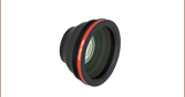
| QS45X-AG | Horizontal | Protected Silver: Rabs ≥ 92% (450 - 500 nm) Rabs ≥ 94.5% (500 - 2000 nm) Rabs ≥ 98% (2 - 10.6 µm) | 45 mm, Converging | Capacitive | ±22.5° Optical | (Click for Graph) Raw Data | 5.1 g·cm2 | 1200 µs | 30.5 mm |
| QS45Y-AG | Vertical | ||||||||
| QS45X-Y1 | Horizontal | Nd:YAG Laser: Rabs ≥ 98% (1064 nm) Rabs ≥ 80% (633 nm) | |||||||
| QS45Y-Y1 | Vertical | ||||||||
各システムにはガルバノスキャンヘッド、ドライバーボード、駆動ケーブルが含まれます。対応する電源GPWR15と電源ケーブルCBLS3Fは別売りでご用意しております(下記参照)。光学系に容易に組み込みが可能となるマウントQSM3/Mも別売りでご用意しています(下記参照)。

 ズーム
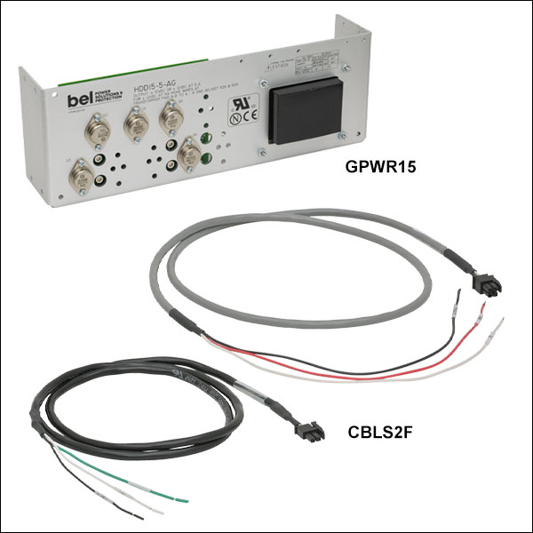
ズーム- GPWR15:1軸および2軸ガルバノシステム用±15 V電源、1個の電源で2つまでのガルバノスキャナの電源供給が可能
- ガルバノスキャナVantagePro® QG/QS/SS/SPシリーズ
- フォーカサBLINK
- スキャンヘッドXGシリーズ
- 電源GPWR15の仕様
- オープンフレーム電源との接続は、ケーブルのはんだ付けが必要
- 入力:100~120または220~240 VAC
- 出力:±15 V @ 5 A(150 W Max Power)
- 動作温度:0~50 °C
- 寸法:356 mm x 124 mm x 90 mm
- CBLS2F:コマンドケーブル&電源ケーブル、ガルバノスキャナQS7/QS10シリーズおよび高速フォーカサBLINK用(1軸につき1セット必要です)
- CBLS3F:コマンドケーブル&電源ケーブル、ガルバノスキャナQG4/5およびQS15/20/30/45シリーズ用(1軸につき1セット必要です)
電源GPWR15は低ノイズのリニア電源で、良好なシステム分解能を得るために電気干渉を最小限に抑える設計がされています。 ガルバノスキャナQG/QS/SS/SPシリーズ、フォーカサBLINK、スキャンヘッドXGシリーズに対応します。電源の出力は5 Aで±15 VDC、100~120 VACに対応します。 オープンフレームのため、対応する電源ケーブルをシステムにはんだ付けすることができます。
コマンドケーブルと電源ケーブルのセットCBLS2Fは、電源GPWR15をQS7/10シリーズガルバノスキャナや、高速フォーカサBLINKに接続するのにご使用いただけます。電源ケーブルの片端にはQS7/10シリーズとBLINKに対応する4ピンコネクタが付いており、もう片端には電源GPWR15をはんだ付けするための3本のワイヤ素線が付いています。コマンドケーブルの片端にはQS7/10シリーズとBLINKに対応する2ピンコネクタが付いており、もう片端にはお手持ちのコントローラをはんだ付けするための3本のワイヤ素線が付いています。
電源ケーブルとコマンドケーブルのセットCBLS3Fは、電源GPWR15をガルバノスキャナQG4/5、およびQS15/20/30/45やSS、SPシリーズに接続するためにご使用いただけます。電源ケーブルの片端には3ピンコネクタが付いており、もう片端には電源GPWR15をはんだ付けするための3本のワイヤ素線が付いています。コマンドケーブルの片端には4ピンコネクタが付いており、もう片端にはお手持ちのコントローラをはんだ付けするための3本のワイヤ素線が付いています。

 ズーム
ズーム- GPS011-JP:1軸および2軸ガルバノシステム用±15 V電源、1個の電源で2つまでのガルバノスキャナの電源供給が可能
- ガルバノスキャナVantagePro® QS7、QS10、QS15、QS20シリーズ
- フォーカサBLINK
- スキャンヘッドXGシリーズ
- 電源GPS011-JPの仕様
- システムにケーブルを直接接続できる筐体付き電源
- スイッチング電源:100 VAC / 50または60 Hz、115 VAC / 60 Hz、230 VAC / 50 Hz
- 出力: ±15 VDC @ 3 A
- 動作温度:5~40 °C
- 寸法(L×W×H):179 mm x 274 mm (Max) x 122 mm
- CBLS2P:コマンドケーブル&電源ケーブルセット、ガルバノスキャナQS7/10シリーズおよび高速フォーカサBLINK用
- CBLS3F:コマンドケーブル&電源ケーブルセット、ガルバノスキャナQG4/5とQS15/20シリーズ用
電源GPS011-JPは1軸または2軸のガルバノシステム用低ノイズのリニア電源で、良好なシステム分解能を得るために電気干渉を最小限に抑える設計がされています。ガルバノスキャナQG4/QG5/QS7/QS10/QS15/QS20シリーズ、フォーカサBLINK、スキャンヘッドXGシリーズに対応します。 電源の出力は3 A で±15 VDC、100 VACの入力に対応します。筐体付きの電源のため、電源ケーブルははんだ付けせずに直接接続できます。
なお、電源GPS011-JPは、ガルバノスキャナQS30/45シリーズの駆動には十分ではありませんのでご注意ください。また、対応するガルバノスキャナについてもRMSを1 A未満に維持することをお勧めいたします。
電動ケーブル&コマンドケーブルセットCBLS2Pは、電源GPS011-JPをガルバノスキャナQS7/10シリーズや高速フォーカサBLINKにつなげるのにご使用いただけます。電源ケーブルの片端にはGPS011-JPに対応する3ピンの円形コネクタ、もう片端にはフォーカサBLINKとガルバノスキャナQS7/10シリーズに対応する4ピンコネクタが付いています。コマンドケーブルの片端にはお手持ちのコントローラに対応するBNCコネクタ、もう片端にはフォーカサBLINKとガルバノスキャナQS7/10シリーズに対応する2ピンコネクタが付いています。
電動ケーブル&コマンドケーブルセットCBLS3Pは、電源GPS011-JPをガルバノスキャナQG4/5とQS15/20シリーズにつなげるのにご使用いただけます。電源ケーブルの片端にはGPS011-JPに対応する3ピンの円形コネクタ、もう片端にはガルバノスキャナQG4/5およびQS5/20シリーズに対応する3ピンコネクタが付いています。コマンドケーブルの片端にはお手持ちのコントローラに対応するBNCコネクタ、もう片端にはガルバノスキャナQG4/5およびQS15/20シリーズに対応する4ピンコネクタが付いています。

 ズーム
ズーム
Click to Enlarge
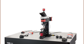
Figure G11.3 ガルバノスキャナQS20Y-AGを垂直方向に配置したマウントQSM2/Mをポスト上に設置

| Table G11.1 Specifications | ||
|---|---|---|
| QSMx Mount | Drawingsa | Compatible QSx Galvonometer |
| QSM1(/M) |  | QS7 or QS10 |
| QSM2(/M) |  | QS15 or QS20 |
| QSM3(/M) |  | QS30 or QS45 |
| QSM4(/M) |  | QG4 or QG5 |
- Ø4 mm~Ø45 mm 1軸ガルバノスキャナ(別売り、上記参照)用マウント
- ツーピースタイプのクランプ機構によりミラー表面との接触防止
- ポストまたは移動ステージに垂直方向または水平方向に取り付け可能
- 移動ステージMTシリーズの上に繰り返し精密に取り付けられる位置決めPIN用穴・スロット
- ヒートシンクGHS003/Mに対応
マウントQSMx/Mは上記の1軸ガルバノスキャナQSおよりQGシリーズ用です。Table G11.1の図では、ポストや移動ステージに垂直方向または水平方向に取り付けるための穴の配置がご覧いただけます。ガルバノスキャナはツーピースタイプのクランプに固定されるので、変動に敏感なミラーをマウントに通さずに固定が可能です。駆動信号波形の変動が大きく、さらなる放熱が必要な用途向けに、すべてのマウントはヒートシンクGHS003/Mに取り付け可能です。1軸ガルバノスキャナに取り付け可能なマウントについてはTable G11.1をご覧ください。
マウントQSM3/Mには、静電容量式位置検出器を電気ノイズから保護するプラスチック製の絶縁シム(厚さ0.05 mm)が付いています。電気絶縁のため、取付前のガルバノスキャナにシムを巻くことをお勧めします。