 Products Home
エルビウム添加ファイバー増幅器(EDFA)

- Saturation Output Power of >20 dBm or >24.5 dBm
- Single Mode or Polarization-Maintaining Output
- Low-Noise, High-Gain Performance
- Turnkey Benchtop Systems or PXIe Plug-in Modules
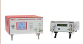
EDFA300P
Polarization-Maintaining EDFA, >24.5 dBm Output Power
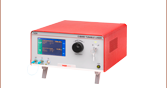
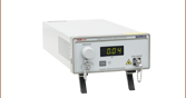
EDFA100S
Single Mode EDFA, >20 dBm Output Power
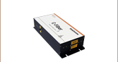
EDFA300SX
PXIe Plug-In Module,
>24.5 dBm Output Power


Please Wait
| Table 1.1 Key System Specificationsa | |||||
|---|---|---|---|---|---|
| Item # | EDFA100S(X) | EDFA100P(X) | EDFA300S(X) | EDFA300P(X) | |
| Output Powerb (@ 3 dBm Input Power) | > 20 dBm | > 24.5 dBm | |||
| Small Signal Gainb (@ -20 dBm Input Power) | > 30 dB | > 28 dB | > 40 dB | ||
| Noise Figureb (@ 3 dBm Input Power) | < 5 dB | < 6 dB | |||
| Polarization Extinction Ratio | N/A | > 25 dB | N/A | > 25 dB | |
| Polarization-Dependent Gain | < 0.5 dB | N/A | < 0.5 dB | N/A | |
| Table 1.2 Feature Comparison | |||||
|---|---|---|---|---|---|
| Item # | EDFA100S/ EDFA100P | EDFA100SX/ EDFA100PX | EDFA300S/ EDFA300P | EDFA300SX/ EDFA300PX | |
| Front Panel Interface |  | - | | - | |
| Current Control Mode | | a | | a | |
| Power Control Mode | - | a | a | a | |
| Gain Control Mode | - | a | a | a | |
| Remote Control Interface | USB | PXIe | USB | PXIe | |
特長
- 動作波長範囲:1530~1565 nm(Cバンド)
- 8種類のモデルをご用意(Table 1.1と1.2参照)
- シングルモードファイバ光増幅器はベンチトップシステムか プラグインモジュールの形態でご用意
- データ通信リンクでのプリアンプまたはブースターアンプに適した製品
- 短パルス用途向けに低分散の設計
- 前面パネルでの制御およびUSB経由でのリモート制御が可能
- カスタム仕様の分散補償パッチケーブルもご要望に応じてご提供しております。詳細は当社までお問い合わせください。
- 光増幅器EDFA100シリーズに対応した利得平坦化フィルタもご用意しています。
コア励起エルビウム添加ファイバ増幅器(EDFA)は、高い小信号利得と出力パワーをもたらします。コンパクトなターンキー式ベンチトップか、プラグインPXIeモジュールに収められており、FC/APC(2.0 mmナローキー)入出力コネクタが付いています。2種類の出力パワーの製品をラインナップしております。EDFA100シリーズ増幅器は20 dBm以上、EDFA300シリーズは24.5 dBm以上を出力できます。増幅器EDFA100シリーズでは分散が0.06 ps/nm以下でパルスの広がりを最小に抑えるため、フェムト秒パルスの増幅に適しています。詳細については「フェムト秒パルスの増幅」タブをご覧ください。増幅器EDFA300シリーズは、EDFA100シリーズよりも出力と利得が高く、ブースターアンプとしてご使用いただけます。仕様の詳細については「仕様」タブ、典型的な性能については「グラフ」タブをご覧ください。
EDFAではシングルモードファイバに加え、偏波保持ファイバのモデルもご用意しております。シングルモード光増幅器EDFA100S(X)およびEDFA300S(X)は、偏光無依存で、増幅器の入出力ファイバには標準的なシングルモードファイバSMF-28-J9が使用されています。偏波保持ファイバ増幅器EDFA100P(X)およびEDFA300P(X)は、偏光依存で、スロー軸に沿った直線偏光のみを増幅します。こちらの増幅器に使用されている入出力ファイバは偏波保持ファイバPM1550-XP)で、コネクターキーはファイバのスロー軸にアライメントしています。
動作モード
増幅器EDFA100シリーズの利得と出力を決定する励起光源の電流は、機器の前面パネルから制御できますが、USB 2.0コネクタを介したリモート操作によっても変更できます。増幅器EDFA300シリーズの動作モードは、電流、出力、利得の3種類のパラメータによる制御が可能です。電流制御は機器の前面パネルおよびUSBを介したリモート操作で可能ですが、出力調整と利得調整モードはコマンドラインインターフェイスを通じてのみとなります。
各増幅器は、それぞれPXIeシャーシで使用できるように設計されたプラグインモジュールのタイプもご用意しています。 これらのプラグインモジュールは、定電流、定光出力、定利得の3つのモードで動作可能です。3つの全てのモードはPXIeシャーシにPCを接続することで制御できます。
形状、消費電力、光学特性についてカスタム仕様のEDFAを必要とする場合には、当社までお問い合わせください。当社では、1025~1075 nmで動作するイッテルビウム添加ファイバ増幅器(YDFA)や、1280~1330 nm(Oバンド)で動作するプラセジウム添加ファイバ増幅器(PDFA)もご用意しております。
利得平坦化フィルタ
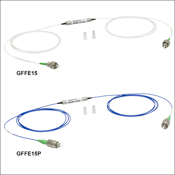
当社では、幅広いスペクトル領域にわたり均一な利得を必要とする用途向けに、ファイバ増幅器EDFA100シリーズの利得スペクトルを平坦化できる利得平坦化フィルタをご用意しております(別売り、下記参照)。フィルタはEDFA100S(X)に対応するシングルモードモデル(型番GFFE15)とEDFA100P(X)に対応する偏波保持モデル(型番GFFE15P)があります。

特記のない限り、下記の全ての仕様はCW入力の場合のみ有効です。
| Item # | EDFA100S(X) | EDFA100P(X) |
|---|---|---|
| Amplifier Specifications (@ 1000 mA Pump Current) | ||
| Operating Wavelength Rangea | 1530 - 1565 nm | |
| Saturated Output Powerb,c (@ 3 dBm Input Power) | > 20 dBm | |
| Small Signal Gainb (@ -20 dBm Input Power) | > 30 dB | > 28 dB |
| Noise Figureb (@ 3 dBm Input Power) | < 5 dB | |
| Output Power Stabilityd (Constant Current Modee @ 3 dBm Input Power) | < ±2% Over 24 Hours | |
| Output Power Stabilityd (Constant Power Mode @ 3 dBm Input Power) | < ±0.5% Over 24 Hour (EDFA100 Series PXIe Modules Only)f | |
| Total Dispersion Within Amplifierg | < 0.06 ps/nm | |
| Laser Class | 3B | |
| Fiber Specifications | ||
| Output Polarization | Random | Linear, Aligned to Slow Axis |
| Polarization Extinction Ratio | N/A | > 25 dB |
| Polarization-Dependent Gain | < 0.5 dB | N/A |
| Return Loss at Input Port | > 50 dB | |
| Input / Output Isolation | > 30 dB | |
| Input / Output Fiber Type | SMF-28-J9 | PM1550-XP |
| Input / Output Fiber Connectors | FC/APC Compatible, 2.0 mm Narrow Key | |
| Absolute Maximum Ratings | |
|---|---|
| Absolute Maximum Input Power | 10 dBm |
| Absolute Maximum Output Power | 23 dBm |
| Operating Temperature | 15 to 35 °C |
| Storage Temperature | 0 to 50 °C |
| General Specifications | ||
|---|---|---|
| Item | EDFA100 Series Benchtop Systems | EDFA100 Series PXIe Modules |
| Input Voltage | 100 - 240 VAC, 50 - 60 Hz | - |
| Input Power | 20 VA (Max) | - |
| Fuse Rating | 500 mA | - |
| Fuse Type | IEC60127-2/III (250 VA, Slow Blow Type "T") | - |
| Electrical Power (From PXIe Chassis) | - | 12 W (1 A @ 12 V)a |
| Dimensions (W x H x D) | 146.3 mm x 77.7 mm x 308.9 mm (5.76" x 3.06" x 12.16") | 40.3 mm x 128.7 mm x 207.2 mm (1.59" x 5.07" x 8.16") |
| Weight | 2.08 kg (4.58 lbs) | 0.45 kg (1 lb) |
特記のない限り、下記の全ての仕様はCW入力の場合のみ有効です。
| Item # | EDFA300S(X) | EDFA300P(X) |
|---|---|---|
| Amplifier Specifications (@ Max Pump Currenta) | ||
| Operating Wavelength Rangeb | 1530 - 1565 nm | |
| Saturated Output Powerc,d | > 24.5 dBm | |
| Small Signal Gainc (@ -20 dBm Input Power) | > 40 dB | |
| Noise Figurec (@ 3 dBm Input Power) | < 6 dB | |
| Output Power Stabilitye (Constant Current Mode @ 3 dBm Input Power) | < ±2% Over 24 Hours | |
| Output Power Stabilitye (Constant Power Mode @ 3 dBm Input Power) | < ±0.5% Over 24 Hours | |
| Total Dispersion Within Amplifierf | < 0.14 ps/nm | |
| Laser Class | 3B | |
| Fiber Specifications | ||
| Output Polarization | Random | Linear, Aligned to Slow Axis |
| Polarization Extinction Ratio | N/A | > 25 dB |
| Polarization-Dependent Gain | < 0.5 dB | N/A |
| Return Loss at Input Port | > 50 dB | |
| Input / Output Isolation | > 30 dB | |
| Input / Output Fiber Type | SMF-28-J9 | PM1550-XP |
| Input / Output Fiber Connectors | FC/APC Compatible, 2.0 mm Narrow Key | |
| Absolute Maximum Ratings | |
|---|---|
| Absolute Maximum Input Power | 13 dBm |
| Absolute Maximum Output Power | 26 dBm |
| Operating Temperature | 15 to 30 °C |
| Storage Temperature | -10 to 40 °C |
| General Specifications | ||
|---|---|---|
| Item | EDFA300 Series Benchtop Systems | EDFA300 Series PXIe Modules |
| Input Voltage | 100 - 240 VAC, 50 - 60 Hz | - |
| Input Power | 20 W (Max) | - |
| Fuse Rating | 2 A, 250 V | - |
| Fuse Type | Time-Lag (Slow-Blow) | - |
| Fuse Size | 5 mm x 20 mm | - |
| Electrical Power (From PXIe Chassis) | - | 12 W (1 A @ 12 V)a |
| Dimensions (W x H x D) | 250.0 mm x 122.2 mm x 300.0 mm (9.84" x 4.81" x 11.81") | 40.3 mm x 128.7 mm x 207.2 mm (1.59" x 5.07" x 8.16") |
| Weight | 3.4 kg (7.5 lbs) | 0.45 kg (1 lb) |
性能グラフ
EDFA100シリーズの性能グラフはEDFA100S(X)とEDFA100P(X)の代表値であり、特記のない限り、CW入力、1000 mAの最大励起電流および25 °Cの励起レーザの温度設定の条件で取得されています。EDFA300シリーズの性能グラフは最大の励起レベルで取得しており、また、EDFA300S(X)とEDFA300P(X)の代表値です。なおこのデータは当社のEDFAの典型的な性能であり、参考値です。すべてのモデルで保証されている仕様は「仕様」タブでご覧いただけます。
出力パワー

Click to Enlarge
生データはこちら
EDFA300シリーズベンチトップシステムとEDFA300シリーズPXIeモジュールとの励起レーザ電流に対する1550 nmにおける出力パワー(典型値)。EDFA300シリーズPXIeモジュールの励起レーザ電流は、パーセンテージではなくmAに指定されていることにご留意ください。EDFA300シリーズPXIeモジュールの最大電流は1000 mAです。すべての電流値は最大1000 mAに正規化することにより、パーセンテージに変換できます。
利得
Click to Enlarge
生データはこちら
EDFA100シリーズの波長に対する利得(典型値) 青色の網掛け領域は動作波長範囲を示しています。 幅広い波長範囲にわたり均一な利得を必要とする用途向けに、EDFA100x用の利得平坦化フィルタもございます(下記参照)。
NF(Noise Figure: 雑音指数)

増幅器EDFA100xシリーズのフェムト秒パルスの増幅
エルビウム添加ファイバ増幅器は半導体光増幅器(SOAやBOA)などの半導体の光増幅器に比べ、フェムト秒パルスを非常に高いピークパワーに増幅します。この増幅のメカニズムについての詳細は、このタブの最後にある増幅器の比較セクションでご覧いただけます。
ここでは、430 fs FWHMの入力パルスが1550 nmにおいて増幅器EDFA100Pを伝搬することによる時間プロファイルへの影響を測定しました。
実験のセットアップ
エルビウムファイバ発振器により中心波長1550 nmのフェムト秒パルスレーザを生成します。パルスの3 dB帯域幅(スペクトル)の測定値は9 nmとなり、フーリエ限界パルス幅は290 fs FWHMとなります。オートコリレータではこのパルス幅は430 fs FWHMとして測定されます。このファイバ発振器の平均出力パワーは1.1 mWとなります。ファイバ発振器の繰り返し周波数は50 MHzなので、パルスエネルギは22 pJになります。
これらの430 fs FWHM、22 pJのパルスが、増幅器EDFA100P内を伝搬します。その際、ファイバ発振器は増幅器に直接接続されている場合もあれば、分散補償ファイバーパッチケーブルを中間部品として使用して増幅器に接続されている場合もあります。出力パワーの合計はEDFA100Pの励起電流を調整すると変化します。オートコリレータを用いて、出力パワーに対する増幅された出力パルスの時間プロファイルを測定しました。
結果
増幅された出力パルスを0.3 nJ、0.6 nJ、1.1 nJの3種類で設定しました。測定は出力パルスエネルギが1.1 nJになったら中止します。時間プロファイルの中に非線形性が出現するためです。各グラフのデータは規格化されており、自己相関性を比較しやすくなっています。
Click to Enlarge
Figure 4.1 増幅器の出力パルスエネルギを0.3 nJに設定した場合、出力パルスの時間プロファイルの歪みは最小となります。分散補償ファイバ(DCF)を使用すると、出力パルスは150 fsに圧縮されます。
| 0.3 nJ Test | Measured Pulse Width (FWHM) | Calculated Peak Power |
|---|---|---|
| Input Pulse | 430 fs | 45 W |
| Output Pulse (No DCF Precompensation) | 570 fs | 0.46 kW |
| Output Pulse (-0.05 ps/nm DCF Precompensation) | 150 fs | 1.76 kW |
Click to Enlarge
Figure 4.2 増幅器の出力パルスエネルギが2倍の0.6 nJとなった場合でも、補償していない出力パルスの歪みは見られません。分散補償すると出力パルスは88 fsに圧縮されますが、両側には非線形現象に伴うサブピークが発生します。補償した出力パルスのピークパワーは6 kWとなります。
| 0.6 nJ Test | Measured Pulse Width (FWHM) | Calculated Peak Power |
|---|---|---|
| Input Pulse | 430 fs | 45 W |
| Output Pulse (No DCF Precompensation) | 480 fs | 1.1 kW |
| Output Pulse (-0.05 ps/nm DCF Precompensation) | 88 fs | 6 kW |
Click to Enlarge
Figure 4.3 出力パルスエネルギをさらに2倍の1.1 nJにすると、未補正のパルスにも大きな歪みが発生します。-0.05 ps/nm DCFによる補償後は、両側に大きなサブピークが発生しています。DCFを更に-0.14 ps/nmにして補正すると非線形性はほとんどなくなりますが、出力パルスは970 fsに広がります。
| 1.1 nJ Test | Measured Pulse Width (FWHM) | Calculated Peak Power |
|---|---|---|
| Input Pulse | 430 fs | 45 W |
| Output Pulse (No DCF Precompensation) | 140 fsa | - |
| Output Pulse (-0.05 ps/nm DCF Precompensation) | 80 fsa | - |
| Output Pulse (-0.14 ps/nm DCF Precompensation) | 970 fs | 1 kW |
結論
表とグラフから、出力パルスのピークパワーが約1 kW以下では、出力パルスの時間プロファイルにおける非線形性がほとんど見られないことがわかります(正確なピークパワーのリミット値はB-integralの計算により明らかになります。この値は非線形光学では重要な意味を持ちます)。ピークパワーが約1 kWを超えると、自己位相変調や他の非線形光学素子の影響によりスペクトルが広がり、その結果パルス幅が圧縮され、時間プロファイルが歪みます。パルス上のイニシャルチャープ(すなわち光増幅器の分散)とパルスエネルギのバランスに留意することで、低歪みで非線形の影響の小さなパルスを作り出せます。
この例は、Figure 4.2の0.6 nJの事例で示されています。フェムト秒エルビウム発振器と補正済みファイバを用いると、増幅器EDFA100Pはピークパワー6 kWで100 fs未満のパルスを作り出すことができます。補正済みのファイバを使用しない場合でも、出力パルス(およびB integral値)を非線形閾値よりも低く保つことで、この光増幅器は時間歪みを抑えつつ高い利得を実現します。
増幅器の比較
EDFAやYDFAのようなファイバ増幅器は、一般的に半導体光増幅器(BOAやSOA)よりもフェムト秒パルスの増幅に適しています。これら2つのタイプの増幅器は、飽和エネルギ、利得飽和のダイナミックス、自由キャリアの寿命といった点で異なります。半導体増幅器の飽和エネルギは比較的小さく、数pJ程度です。そのため、半導体増幅器によって増幅できるパルスエネルギには限界があります。これに対し、ファイバ増幅器の飽和エネルギのレベルはµJ以上です。また、半導体増幅器の利得回復時間はキャリア寿命によって決まり、10 ps~100 ps程度です。一方、ファイバ増幅器のキャリア寿命は10 µs~1 msです。
1 MHz程度の繰返し周波数のモードロックフェムト秒レーザの場合を考えてみましょう。半導体増幅器の飽和エネルギよりも十分に低いパルスエネルギの場合、パルスをあまり歪ませることなく増幅できます。しかし、パルスエネルギが飽和エネルギを超えると、1つのパルスの継続時間中に増幅が飽和し、パルスの時間プロファイル内で利得差が発生してパルスの形状が歪んでしまいます。ファイバ増幅器は半導体増幅器よりも飽和エネルギが高いため、そのようなメカニズムに基づく利得飽和は発生しにくくなります。
半導体増幅器の利得回復時間(10 ps~100 ps)は繰返し周期よりも短いため、利得媒体はパルス列の次のパルスが半導体増幅器に到着する前に回復します。従って、上記と同じプロセスが各パルスで繰り返されます。ファイバ増幅器では、自由キャリア寿命(10 µs~1 ms)は、繰返し周期よりも大幅に長くなります。そのため、ファイバ増幅器はピークパワーではなくパルスの平均パワーに反応するとみなすことができます。
この他にフェムト秒パルスに関連する事項として、増幅器内における非線形過程の相違があります。ファイバ増幅器の非線形応答はほとんど瞬間的に発生しますが、半導体増幅器の非線形応答時間はキャリア寿命時間と関係して10 ps~100 psの時間スケールとなります。パルスエネルギが飽和エネルギを超えると、このpsレベルの応答はパルス歪みを引き起こす原因となります。
EDFA100x用ドライバ
バージョン 2.12.18
Windows®環境において当社のファイバ増幅器EDFA100xを制御するドライバが含まれています。
EDFA100シリーズベンチトップシステムの前面&背面パネル
Click to Enlarge
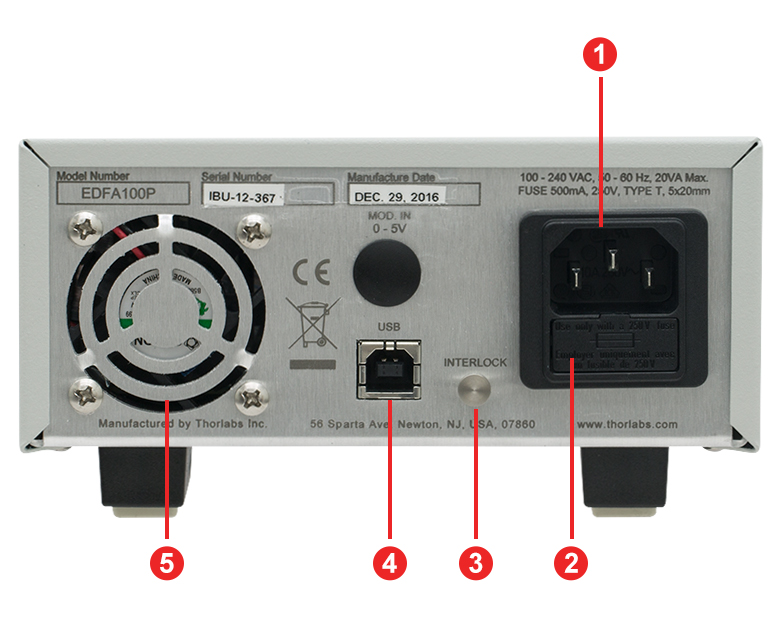
背面パネル
Click to Enlarge
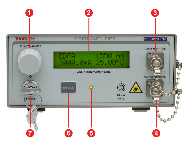
前面パネル
| Back Panel | |
|---|---|
| Callout | Description |
| 1 | AC Power Cord Connector |
| 2 | Fuse Tray |
| 3 | Remote Interlock |
| 4 | USB Port for Remote Interface |
| 5 | Cooling Fan (Do Not Block) |
| Front Panel | |
|---|---|
| Callout | Description |
| 1 | Control Knob to Adjust Pump Laser Current and Temperature |
| 2 | Display to Show Pump Laser Temperature and Drive Current |
| 3 | Optical Input for Single Mode FC/APC Fiber Connector |
| 4 | Optical Output for Single Mode FC/APC Fiber Connector |
| 5 | Amplifier Emission Indicator |
| 6 | Amplifier Enable Switch |
| 7 | Key Switch for Power |
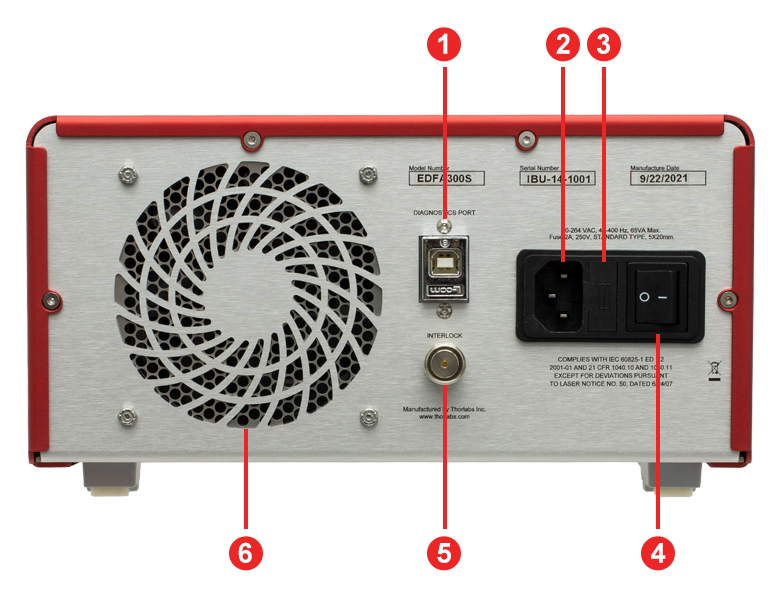
EDFA300シリーズベンチトップシステムの前面&背面パネル
Click to Enlarge
背面パネル

Click to Enlarge
前面パネル
| Back Panel | |
|---|---|
| Callout | Description |
| 1 | USB Port for Diagnostics and Remote Interface |
| 2 | AC Power Cord Connector |
| 3 | Fuse Tray |
| 4 | AC Power Switch |
| 5 | Remote Interlock Input (BNC) |
| 6 | Cooling Fan (Do Not Block) |
| Front Panel | |
|---|---|
| Callout | Description |
| 1 | Key Switch for Power |
| 2 | Display to Show Pump Level, Temperature Status, and Emission Status |
| 3 | Control Knob to Adjust Pump Laser Current |
| 4 | Amplifier Enable Switch and Emission Indicator |
| 5 | Optical Output for Single Mode FC/APC Fiber Connector |
| 6 | Optical Input for Single Mode FC/APC Fiber Connector |
EDFA100シリーズとEDFA300SシリーズPXIeモジュールの前面パネル

| Callout | Description |
|---|---|
| 1 | Output Enable Key-Lock Switch |
| 2 | Remote Interlock Connector: SMB Female |
| 3 | Output: FC/APC |
| 4 | Input: FC/APC |
発送リスト
EDFA100SおよびEDFA100Pに含まれるもの
- ベンチトップ型エルビウム添加ファイバ増幅器
- 増幅器のEnableキー(2個)
- インターロック用短絡ピン
- ファイバーバルクヘッドおよびコネクタ用クリーナFBC250
- 国内対応電源ケーブル
- マニュアル
EDFA300SおよびEDFA300Pに含まれるもの
- ベンチトップ型エルビウム添加ファイバ増幅器
- インターロック用短絡BNCコネクタ
- 国内対応電源ケーブル
- ファイバーバルクヘッドおよびコネクタ用クリーナFBC250
- FC/APCコネクタ付きパッチケーブル、1 m長(出力ポート接続用)
- EDFA300S:シングルモードパッチケーブル(SMF-28 Ultraファイバ) 型番:P3-SMF28Y-FC-1(Ø900 µm被覆付き)、またはP3-SMF28E-FC-1(Ø3 mm被覆付き)
- EDFA300P: 偏波保持(PANDA)パッチケーブル(PM1550-XPファイバ) 型番:P3-1550PMY-1(Ø900 µm被覆付き)、またはP3-1550PM-FC-1(Ø3 mm被覆付き)
- 出力部インターフェイス部品*
*この出力部インターフェイス部品が損傷の際は交換品をご用意しております。当社までお問い合わせください。
EDFA100SX、EDFA100PX、EDFA300SX、EDFA300PXに含まれるもの
- PXIe規格のモジュールパッケージタイプのエルビウム添加ファイバ増幅器
- 増幅器のEnableキー(2個)
- ファイバーバルクヘッドおよびコネクタ用クリーナFBC250
- FC/APCコネクタ用キャップ(2個)
| Posted Comments: | |
user
(posted 2025-04-15 17:18:44.05) Hi, we have a EDFA100S and would like to know if its able to amplify low optical powers on the order of 1nW or -60dBm. Looking around the graphs only goes to -30dBm. jpoling
(posted 2025-04-22 12:58:02.0) Thank you for contacting Thorlabs. The input signal into the EDFA must be at least greater than the background noise that is characteristic of the EDFA in order for the amplified signal to be discernable. For this reason, we would not recommend amplifying signals smaller than -40 dBm. Yi-Ru CHEN
(posted 2024-07-17 10:03:11.713) Hello, do you provide the driver for Windows 11? jpolaris
(posted 2024-07-23 03:41:21.0) Thank you for contacting Thorlabs. We tested the current EDFA100P drivers with a Windows 11 machine and found them to be compatible. These drivers are downloadable from the following link. https://www.thorlabs.com/software_pages/ViewSoftwarePage.cfm?Code=LFL Vladimir Zenin
(posted 2024-07-02 12:37:17.57) Hi Thorlabs,
I am curious about using EDFA100P for amplification of fs laser pulses beyond 1 nJ. In the tab 'fs Pulse Amplification' you mention that the output beyond 1 nJ leads to distortions of the temporal profile of the pulse due to nonlinearities, even when using precompensation. However, what if I first broaden my fs pulse (for example, run it through a fiber), to reduce the peak power, then amplify it, and then compress it with dispersion compensating power?
Another question: you mention that you used 'erbium fiber oscillator' - which one was it?
Thank you in advance! cdolbashian
(posted 2024-07-19 03:35:18.0) Thank you for reaching out to us with this inquiry. It is certainly possible to achieve higher pulse energies given the correct pre-conditioning of your pulse. I have contacted you directly to discuss, theoretically, how you would achieve such performance. Srinivas Bala
(posted 2024-02-19 19:06:37.12) Hello,
We are looking for an EDFA to work with a Menlo Femto Second Optical Frequency Comb to amplify a narrow wavelength range between 1559nm to 1561 nm.
In our process we would filter the output from the Optical Frequency Comb which is +20 dBm @1555-15765nm. After filtering the 10nm band we will have a narrow wavelength between 1559.5nm to 1560.5nm and this would result in low power in the order of -50dbm. Do you have a preamplifier that can handle such a low input? The pulse width will be around 300 fs. Menlo informed us that they buy these EDFA's from you and told us to contact you. We need this Pre Amplifer to have a gain of around 25-30dbm or better and should be powered by 12V DC.
We are not sure if we need a DCF. Please advise.
Thanks
Srinivas ksosnowski
(posted 2024-02-26 01:22:49.0) Hello Srinivas, thanks for reaching out to Thorlabs. Our EDFA's do have small signal gain in the neighborhood of 30dB or better (28dB on the PM version). -50dBm input is well within the -20dBm small signal gain spec. Femtosecond Pulse Amplification is a common application of these fiber amplifiers. We designed the EDFA100 series with <0.06 ps/nm internal dispersion to help minimize pulse broadening. However we do also offer Dispersion Compensating Fiber patch cables if additional compensation is required. While our benchtop units require mains voltage (100 - 240 VAC) to operate, we do offer some PXIe card format options like EDFA100SX which operate on 12V. I have reached out directly to discuss this application in further detail. Yixiu Shen
(posted 2023-12-14 15:31:31.247) I am using the EDFA 100P's with an input power of 3mW, why is the output power not up to the expected amplification or I only have a very small output, I am also experiencing this problem after purchasing a new EDFA of the same type. (I am sure that the wavelength and the fibre used are up to standard) Yazan Lampert
(posted 2023-10-02 22:02:26.0) Dear all,
we would like to know if the polarization dependent gain is caused by the isolator inside the EDFA or if it's caused by the doped fiber its self.
Best,
Yazan cdolbashian
(posted 2023-10-18 04:46:19.0) Thank you for reaching out to us with this inquiry. The polarization dependent gain can be attributed to the pair of isolators with the assembly. I have contacted you directly to discuss this further. Zhenghao Liu
(posted 2023-03-09 12:54:39.86) Hi,
Would you please specify - what is the length of the fiber inside your EDFA100P model?
Many thanks,
Zhenghao jdelia
(posted 2023-03-09 01:58:19.0) Thank you for contacting Thorlabs. The length of fiber inside the EDFA100P is ~ 3.3 m +/- 0.5 m. Rudianto Silitonga
(posted 2022-09-24 16:08:30.167) How do I get your product? jdelia
(posted 2022-09-26 03:16:34.0) Thank you for contacting Thorlabs. You can order our products by adding them to your shopping cart directly on the website or by requesting a quote from our sales team, who you can reach at sales@thorlabs.com or 1-973-300-3000. Nicolas Forget
(posted 2019-10-28 17:09:49.317) Hi, I would like to know whether the EDFA100P can be used both ways, ie with light coming in from both the input and output ports.
Best regards, Nicolas YLohia
(posted 2019-10-29 11:10:36.0) Hello Nicolas, the EDFA is not bidirectional -- the input must be supplied via the "Input Port". If you require a bidirectional operation, then our semiconductor optical amplifiers such as the SOA1117P would be a better fit. The SOA is built with a symmetric structure, so when operating in the reverse direction, the gain will stay the same but saturation power and noise figure may be different. Tiong Leh (Johnny) Yap
(posted 2019-10-16 18:17:04.947) Hi,
I would like to ask for quotation for EDFA100S.
Thank you.
Regards,
Johnny YLohia
(posted 2019-10-16 10:51:11.0) Hello Johnny, thank you for contacting Thorlabs. Quotes can be requested by emailing our Sales Team at sales@thorlabs.com or selecting "Request Quote" from your cart. Yohan Barbarin
(posted 2019-10-08 03:07:20.72) Dear,
We have an issue with the interlock. It looks like it is only mecanical and not electronical.
Could you please give us more information about the electrical specs of the interlock input.
Best regards,
Yohan YLohia
(posted 2019-10-08 02:33:52.0) Hello Yohan, thank you for contacting Thorlabs. The electrical specs for the interlock can be found on Page 10 of the manual: https://www.thorlabs.com/_sd.cfm?fileName=TTN118382-D02.pdf&partNumber=EDFA100S user
(posted 2019-09-04 08:30:52.267) Please can you provide advice on the lowest input power to use with the EDFA100S ?
For example, do you have a graph to show how the SNR in the output varies as a function of the input power ?
The wavelength I want to use is 1550 nm.
I would like to consider input powers down to - 40 dBm, maybe even lower. I notice your graph stops at minus 30 dBm.
Thank you asundararaj
(posted 2019-09-12 01:39:32.0) Thank you for your feedback. The EDFA100S can be seeded with -40 dBm input power. However, the SNR of the output will be reduced as input power is increased. I have contacted you directly to discuss this further. cees de Kok
(posted 2019-03-13 03:54:32.757) We are considering the purchase of the EDFA100P.
We are also working at wavelength on or a little bit below 1520 nm. The gain curve in the documentation which goes as low as 1525 nm seems to still not go down very steeply below 1525...
So my question is: do you have gain-data for 1520 nm or even lower? llamb
(posted 2019-03-15 08:29:36.0) Hello, thank you for your feedback. I have emailed you directly with additional data. k.l.perrier
(posted 2019-03-06 11:08:13.807) We are interested in the Gain and Noise spectrum below 1525nm. Is it possible to provide us the graphs from 1490nm-1570nm or similar range?
Thank you llamb
(posted 2019-03-15 08:23:53.0) Thank you for contacting Thorlabs. I have reached out to you directly with further data. |
、最大出力パワー : 20 dB以上")
 ズーム
ズーム
Click to Enlarge
Figure G1.1 このグラフはEDFA100xの入力パワーに対する出力パワー(3波長)を示しています。データは、CW(連続光)入力、最大励起電流1000 mA、励起温度設定25 °C(デフォルト値)で取得しました。 性能に関するグラフは「グラフ」タブでご覧いただけます。
- 入力信号パワーが-30 dB以上のプリアンプとして適した製品
- 増幅器内で低分散(< 0.06 ps/nm)のため、パルス広がりを抑制
- 非線形性が小さく、超短パルス用途に適した製品
- 定電流モード動作
- CWおよびパルス信号に対応
コア励起エルビウム添加ファイバ増幅器(EDFA100x)は、5 dB以下の低いNF(noise figure)で20 dBm以上の光出力が可能です。EDFA100SはシングルモードのEDFAで、偏光依存性が非常に低くなっています。一方、EFDA100Pは偏波保持EDFAで、ファイバのスロー軸方向の偏光のみ増幅させます。各EDFA100xは入力側、および出力側にアイソレータを内蔵しています。フェムト秒パルスの用途に対応するため、分散が小さくなるように設計されています。フェムト秒パルス入力における動作についての詳細は「フェムト秒パルスの増幅」タブをご参照ください。入出力部でさらに分散補償が必要な場合には、分散補償パッチケーブル(標準品)をご使用になるか、カスタム仕様の分散補償パッチケーブルについて当社 までお問い合わせください。
増幅器EDFA100xの励起電流は前面パネルで調節できるため、お客様ご自身で利得や増幅器の光出力値を変更することができます(「前面&背面パネル」タブ参照)。また、USB 2.0コネクタ経由でシリアルコマンドを送信することで、励起電流のリモート制御も可能です。ドライバは「ソフトウェア」タブからご提供しています。 さらに、安全性を高めるために、背面パネルの2.5 mmモノラルジャックにインターロック回路を接続できるようになっています。
EDFA100xには100~240 VAC、50~60 Hzに対応したユニバーサルACアダプタが付いているので、日本国内での使用時における入力電圧の選択は不要です。また、日本国内対応の電源コードが付属しています。EDFA100xに含まれるものの一覧は「発送リスト」タブでご覧いただけます。
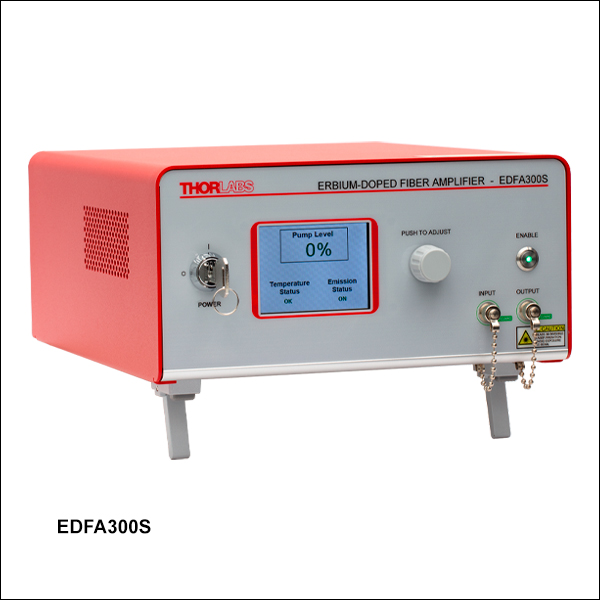
、最大出力パワー: 24.5 dBm以上")
 ズーム
ズーム
Click to Enlarge
Figure G2.1 このグラフはEDFA300xの入力パワーに対する出力パワー(3波長)を示しています。データは励起レベルを100%に設定して取得しています。性能に関するグラフは「グラフ」タブでご覧いただけます。
- 下記の用途に適しています。
- 入力信号パワーが-20 dBm以上のプリアンプ
- プリアンプとパワー増幅器の間のブースタ用途
- 定電流、パワー、利得の動作モード
- CWおよびパルス信号に対応
コア励起エルビウム添加ファイバ増幅器(EDFA300x)は、6 dB以下の低いNF(noise figure)で24.5 dBm以上の光出力が可能です。EDFA300SはシングルモードのEDFAで、偏光依存性が非常に低くなっています。一方、EFDA300Pは偏波保持EDFAで、ファイバのスロー軸方向の偏光のみ増幅させます。EDFA300xには入力側と出力側にアイソレータが内蔵されており、入力レーザ光源を増幅された光や反射光から保護し、励起光が増幅器から出射されないようにしています。入出力部でさらに分散補償が必要な場合には、分散補償パッチケーブル(標準品)をご使用になるか、カスタム仕様の分散補償パッチケーブルについて当社までお問い合わせください。
各ユニットには、長さ1 mのFC/APCパッチケーブルが付属します。こちらのケーブルは、出力部のレセプタクルに接続を繰り返すことによる光損傷から保護するため、常時接続しておいてください。FC/APCコネクタに対応する光出力部インターフェイス部品も付属しており、外部のファイバーケーブルはこのインターフェイスを介して増幅器の出力ポートに接続できます。 なお、このインターフェイス部品を使用することにより挿入損失は約0.7 dB増加しますが、外部のファイバーケーブルと内部のコネクタ表面を直接接続しなくてもよい利点があります。EDFA300xに含まれるものの一覧は「発送リスト」タブでご覧いただけます。
動作モード
EDFA300xは、自動電流制御(Automatic Current Control/ACC)、自動出力パワー制御(Automatic Power Control/APC)、自動利得制御(Automatic Gain Control/AGC)の3つのモードでの動作が可能です。ACCモードではEDFAを一定の励起電流で可能で、前面パネルで操作できます。励起電流レベルを調整することで、利得と出力光パワーを変えることができます。また、こちらのファイバ増幅器は出力光パワーを一定とするAPCモード、および増幅器の利得を一定とするAGCモードでも動作できます。なお、この2つの動作モードはコマンドラインインターフェイスを介してのみ操作することができます。EDFA300xは背面パネルのUSBポートからPCに接続することができます。詳細は「前面&背面パネル」タブをご覧ください。
コマンドラインインターフェイスは、増幅器のEnable/Disable、ACCモードの電流値設定、ステータスインジケータの読み込みなどもできます。USBインターフェイスを介したインジケータとしては、温度エラー、インターロックの状態、光出力の状態があります。これらの機能についての詳細は、機器のマニュアルをご覧ください。
各EDFAには100~240 VAC、50~60 Hzに対応したユニバーサルACアダプタが付いているので、日本国内での使用時における入力電圧の選択は不要です。また、日本国内対応の電源コードが付属しています。
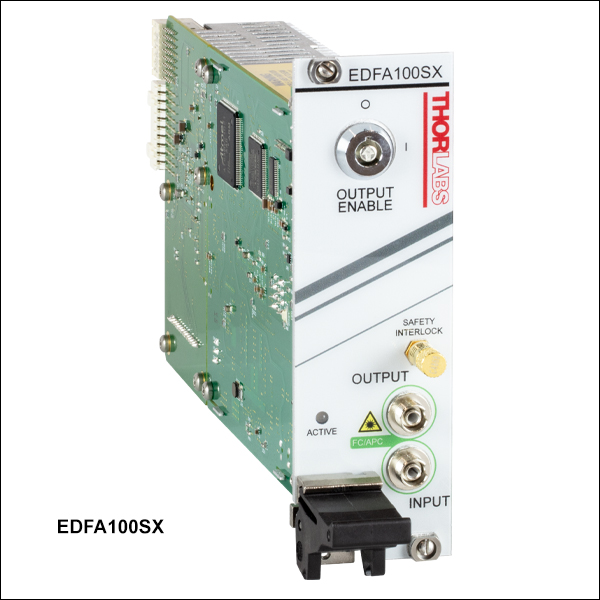
、PXIeモジュール")
 ズーム
ズーム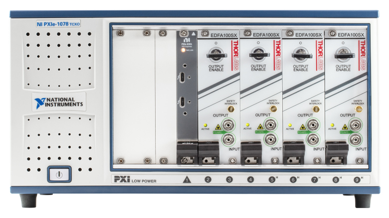
Click to Enlarge
Figure G3.1 PXI対応シャーシ(付属していません)に収められた4つのモジュールEDFA100SX
- 小型のPXIeパッケージ
- ベンチトップ型増幅器EDFA100xまたはEDFA300xと同じ光学性能
- 前面および背面パネルはカスタマイズ可能(詳細は当社までお問い合わせください)
PXI Express (PXIe)プラグインモジュールEDFA100シリーズおよびEDFA300シリーズは、ベンチトップ型増幅器EDFA100xやEDFA300xと光学性能は同じです。モジュールEDFA100SXとEDFA100PXには、ベンチトップ型増幅器EDFA100xの定電流モードに加え、定光出力モードと定利得モードで動作する機能が追加されています。EDFA300シリーズPXIeモジュールは、ベンチトップ型増幅器EDFA300xと同じ3つのモード、定電流モード、定光出力モード、定利得モードで動作します。これらのPXIeモジュールは、新規または既存のPXI試験および測定用セットアップとシームレスな統合が可能で、既存の幅広い光プラグインモジュールと互換性があります。また、モジュールの2スロットPXIカードは小型のため、特に複数のEDFAモジュールを並列で動作させる必要がある場合に、スペース、消費電力およびコストを節約できます。このモジュールは、PXIe対応シャーシ(当社では取扱っておりません)に差し込むだけですぐにご使用いただけます。Figure G3.1では、4つの増幅器EDFA100SXを9スロット付きシャーシに接続した例を示しています。
EDFA100シリーズおよびEDFA300シリーズプラグインモジュールは、PXIコントローラーモジュールを使用したPXIシャーシによってフル制御でき、PC上のシリアルポートとして認識されるため、デバイスとのシリアル通信が可能です。モジュールの制御コマンドはマニュアルでご覧いただけます。また、複数のEDFAカードを1つのPXIeシャーシに接続して駆動可能なLabVIEWインターフェイスもご提供可能です。詳細については当社までご相談ください。

 ズーム
ズーム
Click to Enlarge
Figure G4.1 増幅器EDFA100P(X)に利得平坦化フィルタGFFE15Pを取り付けたときと取り付けていないときの典型的な利得特性。青い網掛け部分は利得が平坦化される波長範囲を示しています。このフィルタは-10 dBmの入力パワーに最適化されています。フィルタを取り付けると利得の平坦度は約3 dBm(赤い実線)から<0.5 dB(赤い点線)に向上します。フィルタ無しの場合、-20 dBmの入力パワーにおける利得の平坦度は大きく変動します(緑の実線)。利得の平坦度はフィルタを1つ取り付けることで向上しますが(緑の点線)、フィルタを2つ使用すると信号はさらに平坦になります(緑の一点鎖線)。入力パワーが0 dBmでの利得スペクトル(青い実線)は、フィルタを使用しても向上しません。
- EDFA100シリーズのエルビウム添加ファイバ増幅器の利得スペクトルを平坦化
- 動作波長範囲: 1525~1570 nm
- -10 dBmの入力パワーに最適化
- シングルモードタイプと偏波保持タイプをご用意
当社の利得平坦化フィルタは、EDFA100シリーズのエルビウム添加ファイバ増幅器(EDFA)に対応します。フィルタはEDFA100S(X)に対応するシングルモードモデル(型番GFFE15)とEDFA100P(X)に対応する偏波保持モデル(型番GFFE15P)がございます。こちらのフィルタはEDFAの出力ポートに接続して使用し、幅広いスペクトル域にわたり均一な利得が必要な用途向けにファイバ増幅器の利得を平坦化することができます。EDFAの利得スペクトルは入力パワーレベルに依存し、入力パワーが減少すると、ゲインの変動は動作波長範囲にわたって増加します。Table G4.2内のフィルタの透過率曲線は、-10dBmの入力パワーにおけるEDFA100シリーズの利得を平坦化します。
利得平坦化フィルタの主な仕様の一つであるピーク-ピーク誤差関数は、透過率曲線の測定値(単位:dB)と透過率曲線の設計値(単位:dB)の差として定義されます。各フィルタの透過プロファイルと設計曲線との誤差は、規定の波長範囲にわたってこの仕様範囲内で変動します。ピーク-ピーク誤差関数は、最大誤差関数と最小誤差関数の差として定義される単一値の仕様です。この値は、Table G4.2内でdBの単位で示されています。
Figure G4.1は、3つの異なる入力パワーレベル(0 dBm、-10 dBm、-20 dBm)における増幅器EDFA100P(X)の利得(典型値)と波長の関係を示しています。このフィルタは、-10 dBmの入力時に最適な利得平坦度が得られるように設計されています(Figure G4.1参照)。1525~1560 nmの波長範囲における-10 dBmの入力パワーでの利得平坦度は、フィルタ無しでは約3 dBですが、フィルタGFFE15Pを取り付けると0.5 dB以下まで向上します。同様に、同じ波長範囲における-20 dBmの入力パワーでの利得平坦度は、フィルタを取り付けることで約8.5 dB程度から6 dB以下程度まで向上します。-20 dBmでの利得は、-10 dBmの場合よりも波長に対して大きな変動を示すため、2つのフィルタをカスケード接続すると、平坦度を4 dB以下程度に向上させることができます(グラフ参照)。2つのフィルタを接続する場合は、ナローキー用FC/APC光ファイバーアダプタADAFC3(シングルモードファイバ用)またはADAFCPM2(偏波保持ファイバ用)のご使用をお勧めいたします。0 dBmの入力パワーレベルにおける増幅器EDFA100P(X)の利得スペクトルは、良好な平坦性を示しているため、これらのフィルタを使用してさらに改善することはできません。
| Table G4.2 Specifications | ||
|---|---|---|
| Item # | GFFE15 | GFFE15P |
| Wavelength Rangea (Click for Design Profile) | 1525 nm - 1570 nm | |
| Insertion Lossb | < 0.8 dB | |
| Peak-to-Peak Error Function | < 0.5 dB | |
| Polarization-Dependent Loss | < 0.1 dB | - |
| Extinction Ratio | - | 20 dB |
| Return Loss | > 50 dB | |
| Connector Type | FC/APC | |
| Fiber Type | SMF-28 In White Ø900 μm Tubing | PM1550-XP In Blue Ø900 μm Tubing |
| Compatible Amplifier | EDFA100S(X) | EDFA100P(X) |