 Products Home
ベンチトップ型ファイバー出力半導体光増幅器(BOAおよびSOA)
- Use as Signal Amplifiers or Optical Shutters
- Center Wavelengths from 1050 to 1625 nm
- Typical Small Signal Gain up to 30 dB
S9FC1137P
Polarization Maintaining
1030 to 1070 nm
S7FC1013S
Polarization Insensitive
1528 to 1562 nm


Please Wait
仕様a
| Item # | Amplifier Type | Center Wavelength | Optical 3 dB Bandwidth | Saturation Output Power @ -3 dB | Signal Gain @ Pin = -20 dBm | Laser Class |
|---|---|---|---|---|---|---|
| S9FC1137P | BOA | 1050 nm | 50 nm | 9 dBm | 21 dB | 1M |
| S9FC1132P | BOA | 1300 nm | 87 nm | 15 dBm | 30 dB | |
| S7FC1013S | SOA | 1550 nm | 74 nm | 14 dBm | 13 dB | |
| S9FC1004P | BOA | 1550 nm | 100 nm | 15 dBm | 28 dB | |
| S9FC1080P | BOA | 1590 nm | 90 nm | 15 dBm | 25 dB | |
| S9FC1082P | BOA | 1625 nm | 80 nm | 13 dBm | 18 dB |
特長
- 中心波長:1050、1300、1550、1590または1625 nm
- 雑音(典型値):< 0.5%
- 飽和出力:9 dBm~15 dBm
- 光入出力部はFC/APCコネクタ付き
- アナログ変調入力(0~5 V)
- 偏光無依存タイプ(SOA)と偏光依存タイプ(BOA)をご用意
- TEC制御により温度は< 0.01 °Cで安定化
- リモート操作用USBインターフェイス
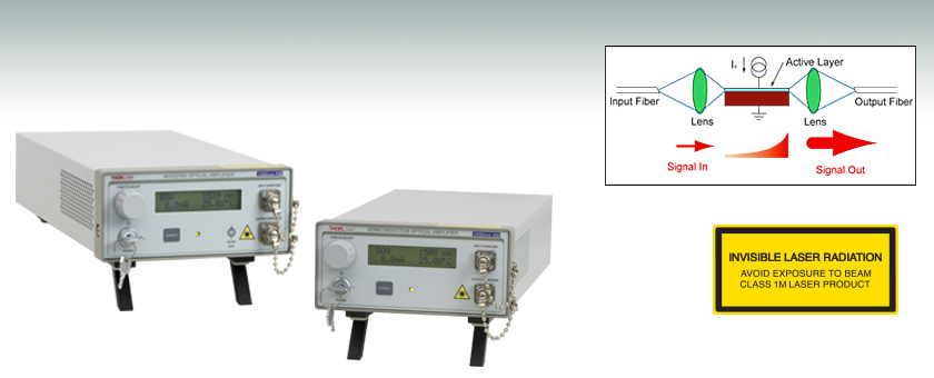
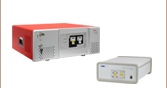
当社の半導体光増幅器に駆動回路や温度調整機構を組み合わせ、使いやすいベンチトップ型にしました。使用方法は簡単です。FC/APCコネクタ付きのファイバーパッチケーブルを入出力端子に接続し、前面パネルのダイヤルで駆動電流と温度を設定します。駆動電流は、ユニット背面にあるBNCコネクタに入力される0~5 V(それぞれゼロ伝達、ならびに最大利得に相当)の信号により、250 kHzまで変調可能です。内蔵のマイクロコントローラが、変調電圧によって光増幅器がオーバードライブにならないよう制御しています。ユニットのLCDディスプレイには光増幅器の駆動電流や測定温度のほか、ユニットの中心波長や増幅器の種類(SOAまたはBOA)が表示されます。光増幅器はUSBインターフェイスによりPCからリモート操作が可能です(コマンドラインインターフェイスからユニットを動作させる際のコマンドのリストは、マニュアルをご覧ください)。
偏光依存型(BOA)と偏光無依存型(SOA)の比較
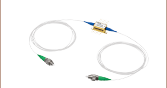
偏光依存型半導体光増幅器(BOA)は偏光感受型のデバイスで、特定の偏光のみ増幅します。偏光依存型(BOA)は、偏波保持ファイバのピグテール付きで、入力ファイバーコネクタのスロー軸にアライメントされた光を増幅します。1050、1300、1550、1590ならびに1625 nmの中心波長でご用意しております。偏光依存型半導体光増幅器(SOA)は、入力偏光状態に関係なく増幅動作します。最大利得は偏光依存型(BOA)より低くなります。こちらは1550 nmの中心波長のみご用意しています。半導体光増幅器の詳細は上記の「光増幅器」タブでもご覧いただけます。
バタフライパッケージの半導体光増幅器については、こちらの製品ラインナップからご覧ください。
偏光無依存型半導体光増幅器 (SOA)
このデータは25 °Cにおける値です。
| Item # | S7FC1013S | ||
|---|---|---|---|
| Min | Typ | Max | |
| Wavelength (nm) | 1528 | 1550 | 1562 |
| Saturation Output Power at -3 dB (dBm) | 12 | 14 | - |
| Optical 3 dB Bandwidth (nm) | 70 | 74 | - |
| Signal Gain @ Pin = -20 dBm (dB) | 10 | 13 | - |
| RMS Gain Ripple (dB) | - | 0.1 | 0.5 |
| Noise Figure (dB) | - | 8 | 9.5 |
| Polarization Dependent Gain (dB) | - | 1.0 | 1.8 |
| Chip Length (mm) | - | 1.5 | - |
| Waveguide Refractive Index | - | 3.2 | - |
偏光依存型半導体光増幅器 (BOA)
このデータは25 °Cにおける値です。
| Item # | S9FC1137P | S9FC1132P | S9FC1004P | S9FC1080P | S9FC1082P | ||||||||||
|---|---|---|---|---|---|---|---|---|---|---|---|---|---|---|---|
| Min | Typ | Max | Min | Typ | Max | Min | Typ | Max | Min | Typ | Max | Min | Typ | Max | |
| Wavelength (nm) | 1030 | 1050 | 1070 | 1290 | 1300 | 1315 | 1530 | 1550 | 1570 | 1570 | 1590 | 1610 | 1600 | 1625 | 1650 |
| Saturation Output Power at -3 dB (dBm) | 6 | 9 | - | 15 | 17 | - | 13 | 15 | - | 12 | 15 | - | 10 | 13 | - |
| Optical 3 dB Bandwidth (nm) | 40 | 50 | - | 80 | 87 | - | 90 | 100 | - | 80 | 90 | - | 70 | 80 | - |
| Signal Gain @ Pin = -20 dBm (dB) | 17 | 21 | - | 27 | 30 | - | 25 | 28 | - | 20 | 25 | - | 14 | 18 | - |
| RMS Gain Ripple (dB) | - | - | 0.5 | - | 0.2 | 0.3 | - | 0.1 | 0.2 | - | 0.05 | 0.2 | - | 0.05 | 0.3 |
| Noise Figure (dB) | - | 11 | 14 | - | 7.0 | 9.0 | - | 7.0 | 9.0 | - | 7.0 | 9.0 | - | 7.0 | 9.0 |
| Chip Length (mm) | 1.5 | - | - | - | 1.5 | - | - | 1.5 | - | - | 1.5 | - | - | 1.5 | - |
| Waveguide Refractive Index | 3.3 | - | - | - | 3.2 | - | - | 3.2 | - | - | 3.2 | - | - | 3.2 | - |
一般的な仕様
この仕様は上の表内の全てのBOAおよびSOAに適用されます。
| Controller Specifications | |
|---|---|
| Performance Specifications | |
| Temperature Setpoint Resolution | ±0.01 °C |
| Temperature Control | TEC |
| Temperature Stability | <0.01 °C |
| Temperature Adjustment Range | 20.00 to 30.00 °C |
| Noise (RMS) | <0.5% Typical (Source Dependent) |
| Analog Modulation Input | 0 - 5 V (Zero Transmission to Maximum Gain) |
| Analog Modulation Bandwidth | 250 kHz for Full Depth of Modulation |
| Rise/Fall Time | 1.4 µsec / 1.6 µsec (For a Square-Wave Modulation Input) |
| Connections | |
| Fiber Ports | FC/APC (One Input and One Output) |
| Modulation Input Connector | BNC (Referenced to Chassis) |
| General | |
| AC Input | 100 - 240 VAC, 50 - 60 Hz |
| Dimensions (L x W x H) | 5.8" x 11.4" x 2.6" (147 x 290 x 66 mm) |
偏光無依存型半導体光増幅器(SOA)のゲイン特性およびASEスペクトル
S7FC1013S:中心波長1550 nm

偏光依存型半導体光増幅器(BOA)のゲイン特性およびASEスペクトル
S9FC1137P:中心波長1050 nm
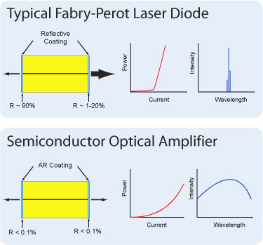
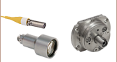
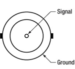
半導体光増幅器(SOAやBOA) の設計はファブリペロー半導体レーザに類似しています。相違点は、ファブリペローレーザでは、半導体チップの両端面に反射コーティングが施されている点です(右図をご参照ください)。両端面からの光のフィードバックが共振器として機能し、レーザが発振されます。半導体光増幅器においては、半導体チップの両端面に反射防止 (AR)コーティングが施されています。ARコーティングがチップへの戻り光を抑制するのでレーザ発振されません。
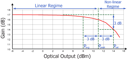
全ての増幅器に共通の典型的な特性ですが、 SOA/BOAは、線形、平坦、一定利得の領域と、非線形の飽和出力の領域の2つの領域で作動します。変調信号を増幅するのに使用されるのは一般に線形領域で、そこではパターン効果、マルチチャンネルクロストーク、エルビウムドープファイバ増幅器(EDFA)でも見られる過度応答といった問題が発生しません。非線形領域は、半導体の利得媒質の高非線形性(相互利得変調や相互位相変調)を活かして、波長変換、光学3R再生、ヘッダ認識、高速光信号処理などに使用されます。
CW入力信号に関して、増幅器が作り出すことのできる出力強度は飽和出力強度(Psat)パラメータで決まります。 Psatは、小信号利得が3 dB落ちた時の出力強度と定義できます。抽出可能な最大CW値は、飽和出力強度と比較しておおよそ 3 dB 高くなります。
変調入力
BNC メス型
250 kHzまで0~5 V
PC接続
USB B型
USBのA型- B型変換ケーブルが付属します。
インターロック
2.5 mm モノラルジャック
デバイスをON の状態にするにはコネクタを短絡させる必要があります。
S7FC1013S用ソフトウェア
Version 1.2.0
半導体光増幅器S7FC1013S操作用ソフトウェアです。システム開発用GUI、ドライバ、LabVIEW/C++ SDK が含まれています。
| Posted Comments: | |
Sungmoon Kim
(posted 2022-04-04 15:52:42.44) Hi! I'm considering the polarization-insensitive SOA device for sensing application. Could you please comment on the stability of the output polarization state? I would like to know how much the output polarization state will change over time. Many Thanks! ksosnowski
(posted 2022-04-13 05:42:44.0) Thanks for reaching out to us Sungmoon. While we do not specify an exact value for stability of the output polarization states, under appropriate drive conditions (stable current and stable temperature), the PDG will be quite stable for SOAs. There may be some slow drift/fluctuation in the beginning as the device comes to thermal equilibrium, but it should stabilize relatively quickly. I've reached out directly to discuss this application further. jian Hu
(posted 2021-09-30 15:32:40.623) Hi!
If my input light is modulated, what is the bandwidth of the modulating frequency? (S7FC1013S)
How to determine the current setpoint? cdolbashian
(posted 2021-10-28 04:04:52.0) Thank you for reaching out to us with this inquiry! This device has a max input bandwidth of ~100GHz. As far as current setpoint, we would always encourage you to start with a low current and increase it slowly to achieve the amplification which you desire. I have reached out to you directly to discuss this further. ZHANG Luan
(posted 2021-02-03 18:45:02.847) Hi,
Thanks a lot for reading this message.
We bought this SOA recently.
I wonder if is can be used bidirectionally.
Can I put the light into the output port and get the amplified light at the input port?
According to the datasheet, there are no isolators inside the SOA.
I should be most grateful if you would reply to me.
All my best,
Luan YLohia
(posted 2021-02-03 11:22:42.0) Hello Luan, thank you for contacting Thorlabs. The SOA is built with a symmetric structure so they can be used bidirectionally. If it is operated backwards, the gain will stay the same, but saturation power and noise figure will be different (if coupling efficiency of input and output fibers are different, which can be true in practice). Gong-Ru Lin
(posted 2020-01-08 21:02:16.883) Dear Sales Engineering,
Can you provide the same unit with SMF package?
Such as S9FC1132S (polarization independent).
Gong-Ru Lin asundararaj
(posted 2020-01-10 04:49:58.0) Thank you for contacting Thorlabs. While we may be able to offer a single mode fiber version of the S9FC1132P as a custom, an alternative would be to use the BOA1132S with the CLD1015. This is usually a preferred option since the polarization in the single mode fiber is sensitive to stresses, vibrations, and changes in temperature. In this case, the fiber itself is accessible when using the CLD1015 for any manipulation for polarization using the fiber polarization controllers. wtxqgg
(posted 2016-10-10 03:34:28.363) What will happen when it is used for a transform limited pulse@1310 nm. The width of the pulse is about 50fs. Will the pulse get wider or get chirped? jlow
(posted 2016-10-13 05:02:26.0) Response from Jeremy at Thorlabs: The SOA/BOA would not be able to amplify a short pulse like this without distorting the waveform. sears
(posted 2015-10-06 09:55:01.81) Can I specify a center wavelength at the short wavelength end (1530nm) given in the specs? I will be using this to amplify an ECDL and I want decent power (20mW +) out to 1500 nm if possible with seeding at 1 mW or so.
Thanks,
Trevor besembeson
(posted 2015-10-13 09:33:01.0) Response from Bweh at Thorlabs USA: I will follow-up regarding this special version. scw52
(posted 2015-07-27 17:41:40.163) Hi, we are using the S9FC1004P optical amplifier (OA) in a fibre-based Mach Zender interferometer, along with your fibres (P1-1550PM-FC-1) and phase modulators (LN65S-FC) to vary the path length.
I have found that feeding the OA output into the interferometer gives interference fringes, even if no input light source is used (i.e. when we are just amplifying noise); the coherence length of the light produced is about 0.1mm. What's more, if we connect a loose optical fibre to the OA input - still with no input light source - the signal is amplified by a factor 10, and the coherence length increases by a factor 10 (approx.). In both cases the maximum fringe contrast (Imax-Imin)/(Imax+Imin) is about 0.9, so these are very prominent fringes.
We are wondering if you know what is causing this effect (presumably the noise amplified has a temporal coherence determined by the amplifier medium's spontaneous decays), particulaly what is happening when we connect a loose fibre.
Please feel free to contact me directly to discuss/clarify this.
Many thanks,
Sid Wright besembeson
(posted 2015-08-21 03:03:37.0) Response from Bweh at Thorlabs USA: I will be contacting you by email. vishalsaxena
(posted 2015-03-13 10:34:10.34) Hi,
I am looking for an optical amplifier for our silicon photonics setup. We work with TE polarization type waveguides. I am trying to decide between polarization maintaining or polarization insensitive optical amplifiers.
Are there selective to one polarization? Do they change the polarization of the output light?
Thanks jlow
(posted 2015-03-24 03:45:54.0) Response from Jeremy at Thorlabs: The SOA series will amplify both polarization states whereas the BOA series will amplify only one polarization state. The advantage of the BOA series is the higher gain achievable. The selection of this will depend on your exact application and how you plan on using them. I will contact you directly to discuss about this further. mark.childers
(posted 2013-12-18 15:00:07.077) You list a possible center wavelength at 1500. I am trying to figure out if this product S7F1013S can amplify 1510, and what would be the saturation output power.
Could you tell me? jlow
(posted 2013-12-19 12:31:34.0) Response from Jeremy at Thorlabs: We guarantee at least 12dBm (14dBm typical) saturation output power for the SOA1013S (the SOA inside the S7FC1013S) over the full range of 1528-1562nm. The saturation output power will be lower at 1510nm; we estimate around 11dBm. The 1500nm number is the center of the ASE curve but the gain curve is typically shifted some to longer wavelengths. |