 Products Home
高耐荷重ピッチ&ヨープラットフォーム
- Low Profile: 25.0 mm (0.98") Height
- ±2.5° Pitch, ±4.0° Yaw
- Various Adjuster Options Available
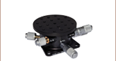
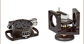
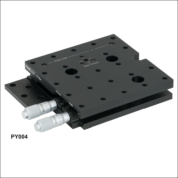
PY004
Pitch and Yaw Platform
Pitch Adjuster
Yaw Adjuster
Yaw
Pitch
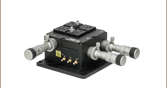
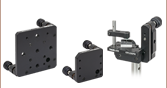
Application Idea
PY004 Pitch/Yaw Platform with HeNe Laser Mounted in V-Clamp
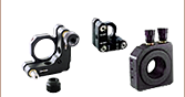
Yaw Adjuster Mount
Pitch Adjuster Mount
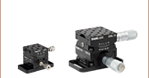
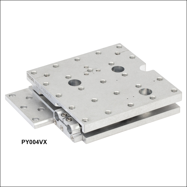
PY004VX
Vacuum Pitch and Yaw Platform
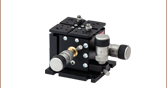
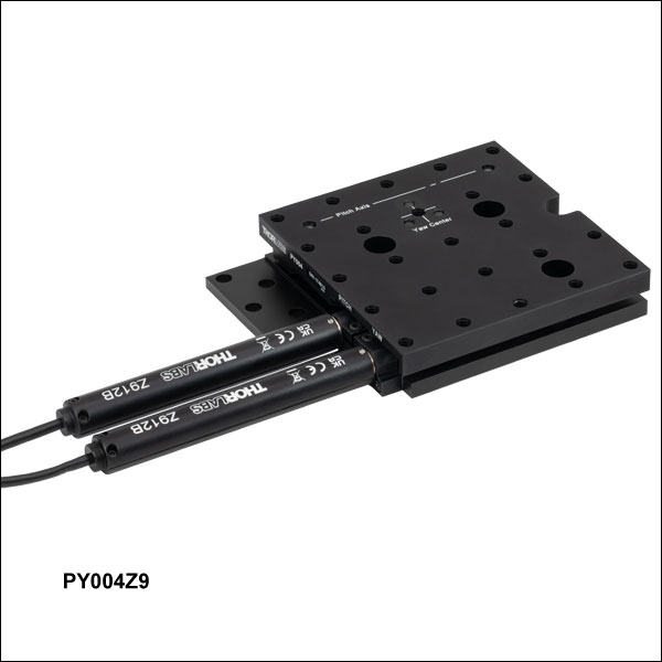
PY004Z9
Pitch and Yaw Platform with DC Servo Actuators
Pitch Adjuster
Yaw Adjuster

Please Wait
| Table 1.1 Key Specificationsa | ||||
|---|---|---|---|---|
| Item # | PY004(/M) | PY004Z9(/M) | PY004VX(/M) | |
| Adjustment Range | Pitch: ±2.5° Yaw: ±4.0° |
|||
| Minimum Incremental Movement | Pitch: 9 arcsecb Yaw: 16.2 arcsecb |
Pitch: 7.13 arcsec Yaw: 15.71 arcsec |
N/Ac | |
| Crosstalk | <0.05° (3 arcmin) | |||
| Horizontal Load Capacity (Max)d | 5.0 kg (11.0 lbs) | 2.0 kg (4.4 lbs) | 5.0 kg (11.0 lbs) | |
| Deck Height | 25.0 mm (0.98") | |||
| Construction | Black Anodized Aluminum | Unanodized Aluminum | ||
| Vacuum Rating | - | 10-6 Torre | ||
| Maximum Bakeout Temperature | - | 130 °Cc | ||
| Operating Temperature | 5 °C to 40 °C (41 °F to 104 °F) | |||
| Included Drives | High-Resolution Micrometers (Qty. 2) | Z912B DC Servo Actuators (Qty. 2) | - | |
Features
- Pitch and Yaw Adjustment
- 1/4"-20 (M6 x 1.0) Tapped Holes with 1.00" (25.0 mm) Spacing
- 0.98" (25.0 mm) Deck Height
- Black Anodized Aluminum (Item #s PY004(/M) and PY004Z9(/M)) or Unanodized Aluminum (Item # PY004VX(/M)) Construction
- Vacuum Compatibility Down to 10-6 Torr (Item # PY004VX(/M))
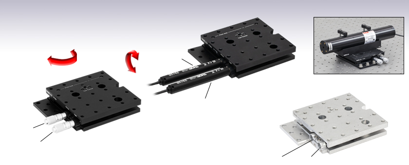
The High-Load Pitch and Yaw Platforms provide ±2.5° of adjustment in pitch and ±4.0° in yaw. They are designed for use with up to 5.0 kg (11.0 lb) loads, such as lasers, cameras, and 3-axis stages (See Figure 1.2). The top platform is equipped with an array of 24 1/4"-20 (M6 x 1.0) threaded mounting holes with 1.00" (25.0 mm) spacing. The actual maximum load will depend on the positioning of the load on the platform. The maximum horizontal load capacity can also be limited by the actuator used with the stage (click here for details).
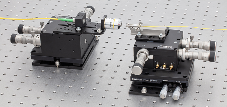
Click to Enlarge Figure 1.2 Two MAX312D 3-Axis Stages Mounted on Two PY004 Stages
Actuator Options
The high-resolution micrometers incorporated into the PY004(/M) stage provide positioning accuracy within 9 arcseconds in pitch and 16.2 arcseconds in yaw. Each revolution of a micrometer gives an angular movement of 0.25° in pitch or 0.45° in yaw. Additionally, these platforms are compatible with other micrometers with a Ø3/8" (Ø9.5 mm) mounting barrel. The stage can also be motorized using our 1/2" travel actuators with Ø3/8" mounting barrels, such as Thorlabs Z912B DC Servo Actuators or ZST213B Stepper Motor Actuators (See Figure 1.4), one for each axis. Alternatively, we offer a motorized PY004Z9(/M) version of the stage with two Z912B DC Servo Actuators included. If desired, the Z912B actuators can be replaced by any manual or motorized actuators with a Ø3/8" (Ø9.5 mm) barrel, including stepper motor actuators and manual micrometers.
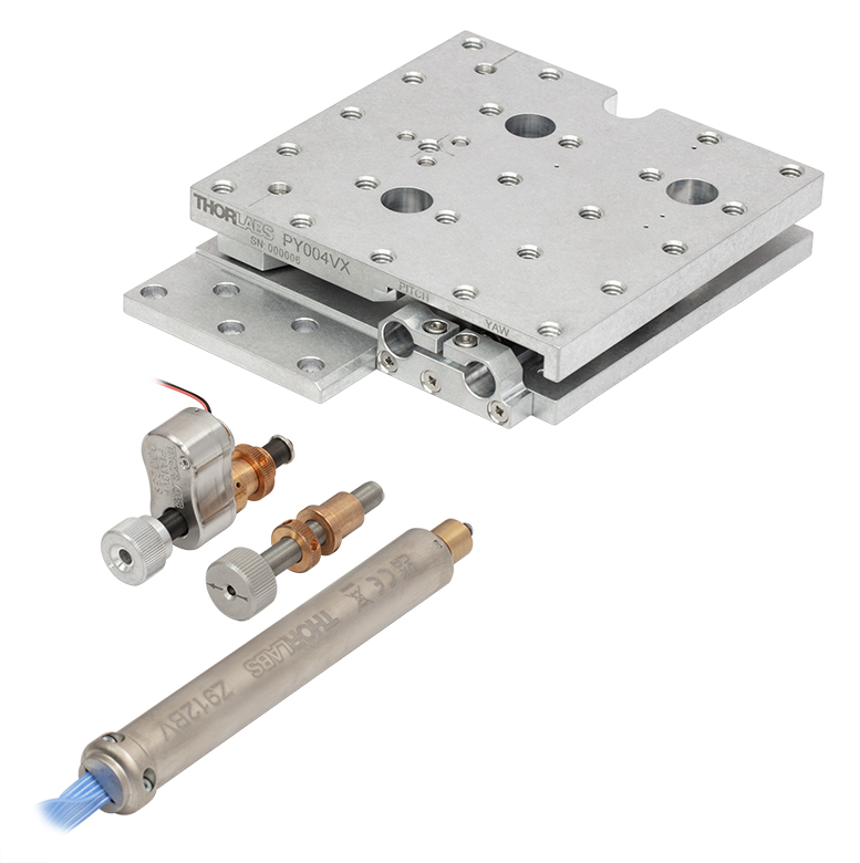
The vacuum-compatible PY004VX(/M) platform can be adjusted using our 1/2" travel actuators with Ø3/8" mounting barrels, such as the Thorlabs PIA13VF Vacuum-Compatible Piezo Inertia Actuator or Z912BV Vacuum-Compatible DC Servo Motor Actuator (sold below). Alternatively, a manual vacuum-compatible actuator can be built, using an F25USA1 Barrel Adapter, LN25100 Lock Nut, a POLARIS-N5 Knob, and an F25US200V Vacuum Adjuster (sold below).
Click to Enlarge
Figure 1.3 PY004VX(/M) Stage Actuator Options (Sold Separately)
Mounting Options
These stages can be mounted directly to a metric or imperial optical table or breadboard using five 1/4" (M6) through mounting holes or the 1/4" (M6) mounting slot. The stages also have three counterbored 1/4" (M6) holes that are revealed by rotating the top plate of the platform. These holes allow the unit to be mounted with the top platform holes in line with the work surface hole pattern or midway off the table's hole pattern. Alternatively, the PY004(/M) platform can be mounted using CL6 clamps secured to the relief cut along the bottom of the stage, and CL6V vacuum-compatible clamps can be used to mount the PY004VX(/M) platform.
Vacuum Compatibility
The PY004VX(/M) platform is a vacuum-compatible version of the PY004(/M) pitch and yaw platform with identical mounting features, accomplished by using vacuum-compatible internal components. Each PY004VX(/M) platform is assembled in a clean environment and double vacuum bagged. Prior to use in a vacuum system, the stages can be baked to remove excess moisture and surface contaminants; however, please note that the maximum baking temperature is 130 °C (with manual vacuum adjusters or PIA13VF actuator) or 85 °C (if using the Z912BV actuator). The platform can be mounted to a breadboard using Thorlabs' CL6V vacuum-compatible clamps and vacuum-compatible fasteners. Thorlabs offers vacuum-compatible breadboards, screws, and other optomechanics that can be can be used with the stage.
Controller Options
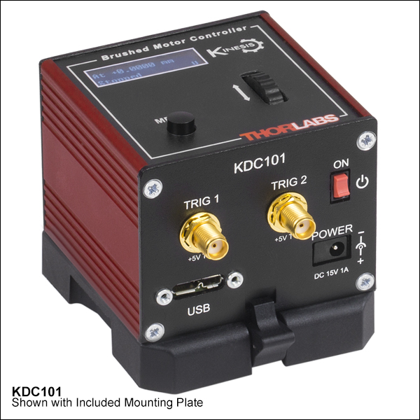
When using platforms with servo motors (e.g., PY004Z9(/M)), Thorlabs recommends using two KDC101 DC Servo Controllers (available below), one for each axis. The latest version of the Kinesis software can be downloaded here. Firmware version 2.2.8 or higher and Kinesis software version 1.14.44 or higher are required for using the KDC101 with the PY004Z9(/M) platforms. Please see the Kinesis Software and Kinesis Tutorial tabs for details. For more information on recommended controllers for particular actuators, see Table G4.1.
Note: PY004VX(/M) units are shipped without actuators and locked in position with transit screws. Two actuators are required. These screws should not be removed until the actuators are correctly fitted to the unit.
| Table 2.1 Specifications | ||||
|---|---|---|---|---|
| Item # | PY004(/M) | PY004Z9(/M) | PY004VX(/M) | |
| Adjuster | High-Resolution Micrometers (Qty. 2) | Z912B DC Servo Actuators (Qty. 2) | - | |
| Adjustment Range | Pitch: ±2.5° Yaw: ±4.0° |
|||
| Minimum Incremental Movement | Pitch: 9 arcseca Yaw: 16.2 arcseca |
Pitch: 7.13 arcsec Yaw: 15.71 arcsec |
N/Ab | |
| Bi-directional Repeatability | N/A | Pitch: 27.85 arcsec, Yaw: 4.75 arcsec | N/Ab | |
| Maximum Velocity | N/A | Pitch: 3600 arcsec/s, Yaw: 3600 arcsec/s | N/Ab | |
| Maximum Acceleration | N/A | Pitch: 3600 arcsec/s2, Yaw: 3600 arcsec/s2 | N/Ab | |
| Crosstalk | <0.05° (3 arcmin) | |||
| Weight (with Adjusters, if Applicable) | 679 g (1.5 lbs) | 870 g (1.91 lbs) | 622 g (1.37 lbs) | |
| Horizontal Load Capacity (Max) | 5.0 kg (11.0 lbs)c | 2.0 kg (4.4 lbs)c,d | 5.0 kg (11.0 lbs)c | |
| Vertical Load Capacity (Max), by Distance from Top Platforme | ||||
| 30 mm (1.18") | 1.8 kg (4.0 lbs) | |||
| 50 mm (1.97") | 1.1 kg (2.4 lbs) | |||
| 80 mm (3.15") | 0.7 kg (1.5 lbs) | |||
| Deck Height | 25.0 mm (0.98") | |||
| Actuator Bushing Diameter | 9.5 mm (3/8") | |||
| Construction | Black Anodized Aluminum | Unanodized Aluminum | ||
| Vacuum Rating | - | 10-6 Torrf | ||
| Maximum Bakeout Temperature | - | 130 °C (266 °F)b | ||
| Operating Temperature | 5 °C to 40 °C (41 °F to 104 °F) | |||
| Table 2.2 Compatible Actuators | |||||||
|---|---|---|---|---|---|---|---|
| Item # | Actuator Type | Values with PY004VX(/M) | |||||
| Minimal Incremental Movement | Bi-directional Repeatability | Maximum Velocity | Acceleration | Horizontal Load Capacity (Max)a | Maximum Bakeout Temperature | ||
| Z912B(V) | DC Servo | Pitch: 7.13 arcsec Yaw: 15.71 arcsec |
Pitch: 27.85 arcsec Yaw: 4.75 arcsec |
Pitch: 3600 arcsec/s Yaw: 3600 arcsec/s |
Pitch: 3600 arcsec/s2 Yaw: 3600 arcsec/s2 |
2.0 kg (4.4 lbs)b | 85°C (185 °F) |
| PIA13(VF)c | Piezo Inertia | Pitch: 54 milliarcsec Yaw: 97.2 milliarcsec |
- | 27.7 - 83.1 arcsec/s | - | 5.0 kg (11.0 lbs) | 130 °C (266 °F) |
| Vacuum Adjusterd | Manual | N/Ae | N/A | N/A | N/A | 5.0 kg (11.0 lbs) | 130 °C (266 °F) |
| ZFS13Bc | Compact Stepper | Pitch: 1 milliarcsec Yaw: 1.6 milliarcsec |
- | 2770 arcsec/s | 9000 arcsec/s2 | 1.8 kg (4.0 lbs) | - |
| ZST213Bc | Stepper | - | |||||
Z912B Connector Pin Out
D-Type Male
| Pin | Description | Pin | Description |
|---|---|---|---|
| 1 | Ground (Limit and Vcc) | 9 | Resistive Identification |
| 2 | Forward Limit | 10 | +5 VDC |
| 3 | Reverse Limit | 11 | Encoder Channel A |
| 4 | Reserved for Future Use | 12 | Reserved for Future Use |
| 5 | Motor (-) | 13 | Encoder Channel B |
| 6 | Reserved for Future Use | 14 | Pin 2 Ident EEPROM |
| 7 | Motor (+) | 15 | Pin 1 Ident EEPROM |
| 8 | Reserved for Future Use |
ソフトウェア
Kinesisバージョン1.14.54
このKinesisソフトウェアパッケージには、当社のKinesisシステムコントローラを制御するためのGUIが含まれています。
下記もご用意しております。
- 通信プロトコル

Figure 58A KinesisソフトウェアのGUI画面
当社のKinesisソフトウェアパッケージを用いて、当社の様々なモーションコントローラを駆動することができます。このソフトウェアは小型で低出力のシングルチャンネルドライバ(K-Cube®など)から、高出力でマルチチャンネルのベンチトップ型ユニットやモジュール型の19インチラックナノポジショニングシステム(ラックシステムMMR60x)まで、当社Kinesisシリーズの様々なモーションコントローラの制御用にご使用いただけます。
Kinesisソフトウェアでは.NETコントロールを使用できるため、最新のC#、Visual Basic、LabVIEW™、あるいはその他の.NET対応言語を使用してカスタムプログラムを作成することができます。.NETフレームワークやAPIの使用を想定していないアプリケーションのために、ローレベルのDLLライブラリも含まれています。中央シーケンスマネージャ(Central Sequence Manager)は、当社のすべてのモーションコントロール用ハードウェアの統合と同期の機能をサポートしています。
この共通のソフトウェアプラットフォームにより、ユーザは単一のソフトウェアツールを習得するだけで、あらゆるモーションコントロールデバイスを1つのアプリケーション内で組み合わせて使用することができます。このように1軸システム用から多軸システム用までのあらゆるコントローラを組み合わせ、それら全てを1台のPCの統合されたソフトウェアインターフェイスから制御できます。
このソフトウェアパッケージには2つの使い方があります。1つはGUI(グラフィカルユーザーインターフェイス)ユーティリティを用いる方法で、コントローラの到着後すぐに直接的な操作と制御を行なうことができます。もう1つは一連のプログラミングインターフェイスを用いる方法で、ご希望の開発言語によりカスタム仕様の位置決めやアライメント用のプログラムを簡単に作成することができます。
Kinesisソフトウェアでは新しい.NETコントロールが使用でき、最新の最新のC#, Visual Basic, LabVIEW™、ほかの.NET対応言語を使用する開発者がカスタムにプログラムを作成することもできます。
C#
このプログラミング言語はマルチプログラミングパラダイムやマルチプログラミング言語が使用可能となるよう設計されているため、複雑な問題が簡単かつ効率的に解決できます。型付け、命令型、宣言型、関数型、ジェネリック、オブジェクト指向、そしてコンポーネント指向が含まれます。 この共通のソフトウェアプラットフォームにより、1セットのソフトウェアツールを習得するだけで、あらゆるKinesisコントローラを簡単に組み合わせることができます。このようにして1軸システムのコントローラから多軸システムのコントローラまで、様々なコントローラを組み合わせ、全てを1台のPCのソフトウェアインターフェイスから制御することが可能となりました。
Kinesisシステムソフトウェアを使用するには2つの手段があります。コントローラを直接つないで制御を行なう付属のGUI(グラフィカルユーザーインターフェイス)ユーティリティ、またはご希望の開発言語でカスタム仕様の位置決めやアライメントを簡単にプログラムできる一連のプログラミングインターフェイスです。
Kinesisモーションコントロールライブラリの構築の参考となる実行可能なプロジェクト機能拡張例については下のリンクをクリックしてください。なお、Quick Startのプロジェクト例の実行には別の統合開発環境(IDE)(Microsoft Visual Studioなど)が必要です。C#のプロジェクト例はKinesisソフトウェアパッケージに付属する.NETコントロールで実行可能です(詳細は「Kinesisソフトウェア」タブをご覧ください)。
 | Click Here for the Kinesis with C# Quick Start Guide Click Here for C# Example Projects Click Here for Quick Start Device Control Examples | |
LabVIEW
LabVIEWは、.Netコントロールを介してKinesisベースのコントローラとの通信に使用できます。LabVIEWでは、ツールとオブジェクトでフロントパネルとして知られるユーザーインターフェイスを構築した後、グラフィカル表記の関数を使ってコードを追加し、フロントパネルのオブジェクトを制御します。下記のLabVIEWチュートリアルでは.Netコントロールを使用してLabVIEW内Kinesis駆動デバイス用の制御GUIを作成するための情報をご提供しています。 LabVIEWでコントローラを制御する基本的な方法や、LabVIEW GUIを用いてデバイスを操作する前に行うべき設定の手順についても解説しています。
 | Click Here to View the LabVIEW Guide Click Here to View the Kinesis with LabVIEW Overview Page | |
| Posted Comments: | |
Pablo Perez-Martin
(posted 2020-09-24 09:58:53.213) Does the PY004/M have a vacuum compatible equivalent? cwright
(posted 2020-09-28 08:28:35.0) Response from Charles at Thorlabs: Hello and thank you for contacting us. Some of our stages can be made vacuum compatible on request and the PY004/M is one of them. We will reach out to you directly regarding the current lead time and pricing. thigulla saikiran
(posted 2020-07-25 01:43:17.787) i want to place that mount in vertical position and the payload on the mount will be around 5Kgs . it can carry the mount load of 5kgs in vertical direction
Regards,
Saikiran DJayasuriya
(posted 2020-08-13 04:34:24.0) Thank you for your inquiry. When mounted vertically the load capacity depends on the load distance from the platform and the load it self. Mounted vertically the maximum load the stage could handle is about 1.8kg approximately and the off axis distance from the platform being 30 mm. David G
(posted 2020-05-21 06:39:57.247) I'm having the same issue as Lawrence (last post below) in understanding how the linear micrometer movement translates to rotation. I also calc that the minimum incremental values (per half division) are twice those stated. Example below is for pitch, but yaw calculation is also wrong.
1 Rev micrometer = 0.5deg = 1800 sec
1 inc micrometer = 1800 sec/50 = 36 sec
1 half inc micrometer = 18 sec (vs 9 sec quoted on website)
Can you clarify? Thanks. DJayasuriya
(posted 2020-06-03 03:52:21.0) Thank you for your inquiry. Due to the mechanism of the stage it wouldn't be a completely linear relationship but between micrometer movement and the rotation.There is a small acute distortion. This also depends how you measure - if the beam is going through the rotation center it will be perfect. In any other cases you will find another numbers as to the rotation of the beam you need to add the movement of the source. If you have any questions please dont hesitate to get in touch with your local technical support team lawrence.berg
(posted 2015-09-15 11:01:19.777) Yet another: Taking pitch on the PY004, minimum incremnental movement is given as 9 arc seconds based on half a division. But at 0.5 degree/rev = 1800 arcsec/rev = 36 arcsec/div. Min inc mov is thus 1/4 division. Am I wrong in assuming 50 divisions/revolution? (Note manual Fig 2.2 implies 100 divisions/revolution also). bwood
(posted 2015-09-17 10:50:44.0) Response from Ben at Thorlabs: Thank you for your feedback messages. The micrometer drives can be removed by loosening a single M3 screw for each actuator, and installing an appropriate Ø3/8" mounting barrel. There is no need to return the stage to be retrofitted. The micrometer itself has a 10µm per division travel, and has a 13mm range. Finally, your calculation does appear to be valid, and I will contact our engineers to clarify this further. I will contact you directly with the results of these discussions. lawrence.berg
(posted 2015-09-15 10:23:24.673) Another question: How much actual travel/revolution is occurring with each micrometer in the PY004 (information needed when looking at motorized options). Thanks lawrence.berg
(posted 2015-09-15 10:01:08.143) Can the PY004 be retrofitted with the motorized micrometer options discussed by the end user? Or must the unit be sent back for retrofit? cflamme
(posted 2014-04-02 09:36:30.877) Does the PY004
have a locking feature?
or do you have a comperable fitures that does cdaly
(posted 2014-04-09 05:16:51.0) Response from Chris at Thorlabs: The PY004 does not have a locking mechanism. While we do have other pitch yaw stages, I'm afraid none of these have this feature either. |

 ズーム
ズーム- Anodized Aluminum Pitch and Yaw Adjustment Stage
- High-Resolution Micrometers Included
- Mounting to Tables and Breadboards Using 1/4" (M6 x 1.0) Mounting Holes or CL6 Table Clamps (Sold Separately)
The PY004(/M) pitch and yaw platform includes high-resolution micrometers and provides ±2.5° of adjustment in pitch and ±4.0° in yaw. It is designed for use with up to 5.0 kg (11.0 lb) loads, such as lasers, cameras, and 3-axis stages. The actual maximum load will depend on the positioning of the load on the platform (click here for details). The top platform is equipped with an array of 24 1/4"-20 (M6 x 1.0) threaded mounting holes with 1.00" (25.0 mm) spacing.
These stages can be mounted directly to a metric or imperial optical table or breadboard using five 1/4" (M6) through mounting holes or the 1/4" (M6) mounting slot. The stages also have three counterbored 1/4" (M6) holes that are revealed by moving the top plate of the platform. These holes allow the unit to be mounted with the top platform holes in line with the work surface hole pattern or midway off the table's hole pattern. Alternatively, the PY004(/M) platform can be mounted using CL6 clamps secured to the relief cut along the bottom of the stage.

 ズーム
ズーム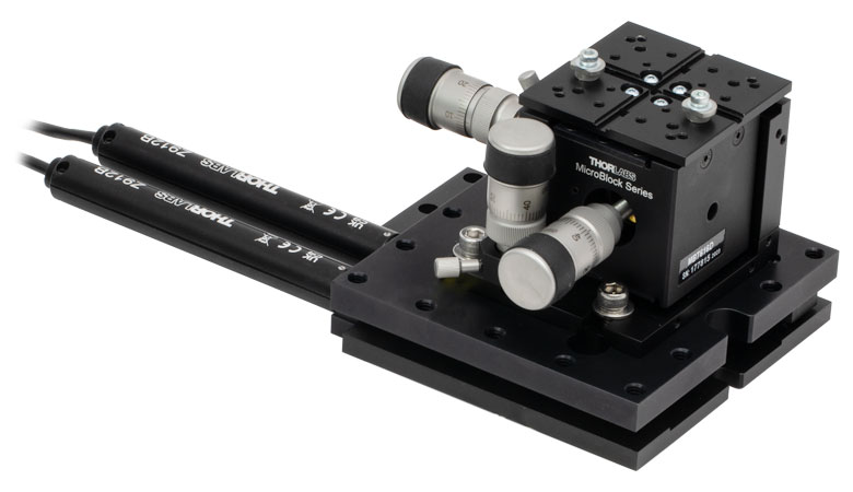
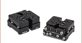
Click to Enlarge
Figure G2.1 Mounting a 3-axis positioner on the PY004Z9 platform results in precision 5-axis control useful in many applications such as fiber alignment.
- Motorized Pitch and Yaw Adjustment via Included DC Servo Actuators
- Maximum Load Capacity: 2.0 kg (4.40 lbs)
- Controllers and Power Supplies Sold Separately
- Mounting to Tables and Breadboards Using 1/4" (M6 x 1.0) Mounting Holes or CL6 Table Clamps (Sold Separately)
Thorlabs' PY004Z9(/M) Motorized Pitch and Yaw Platform provides an adjustment range of ±2.5° and ±4.0° in pitch and yaw, respectively. An array of twenty-four 1/4"-20 (M6) tapped holes allows easy integration with a wide variety of common optomechanical setups. The stage features a maximum load capacity of 2.0 kg (4.4 lbs), making it ideal for use with lasers, cameras, or 3-axis platforms. The actual maximum load will depend on the positioning of the load on the platform (click here for details). The stage requires two controller units and power supplies to operate. For this purpose, we recommend our KDC101

 ズーム
ズーム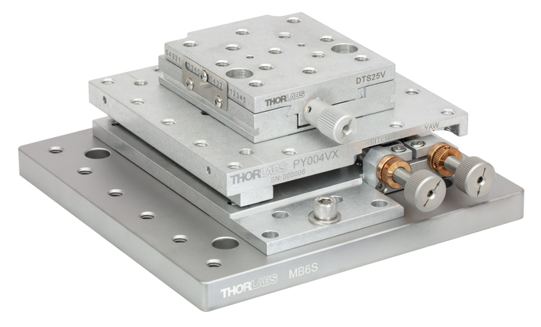
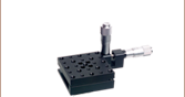
Click to Enlarge
Figure G3.1 PY004VX vacuum pitch/yaw platform with manual vacuum-compatible actuators (built using components sold below) and a DTS25V stage mounted on an MB6S breadboard.
- Vacuum-Compatible Aluminum Pitch and Yaw Adjustment Stage
- Vacuum-Compatible Down to 10-6 Torr
- Packed in a Clean Environment and Double Vacuum-Bagged
- Mounting to Tables and Breadboards Using 1/4" (M6 x 1.0) Mounting Holes or CL6V Table Clamps (Sold Separately)
- Adjusters Available Separately
The PY004VX(/M) pitch and yaw platform provides ±2.5° of adjustment in pitch and ±4.0° in yaw. It is designed for use with up to 5.0 kg (11.0 lb) loads, such as lasers, cameras, and 3-axis stages. The actual maximum load will depend on the positioning of the load on the platform (click here for details) and the actuator used with the stage (see the Specs tab for more information). The top platform is equipped with an array of 24 1/4"-20 (M6 x 1.0) threaded mounting holes with 1.00" (25.0 mm) spacing.
These stages can be mounted directly to a metric or imperial optical table or breadboard using five 1/4" (M6) through mounting holes or the 1/4" (M6) mounting slot. The stages also have three counterbored 1/4" (M6) holes that are revealed by moving the top plate of the platform. These holes allow the unit to be mounted with the top platform holes in line with the work surface hole pattern or midway off the table's hole pattern. Alternatively, the PY004VX(/M) platform can be mounted using CL6V vacuum-compatible clamps secured to the relief cut along the bottom of the stage.
Adjuster Options
The vacuum-compatible PY004VX(/M) platform can be adjusted using our 1/2" travel actuators with Ø3/8" mounting barrels, such as the Thorlabs PIA13VF Vacuum-Compatible Piezo Inertia Actuator or Z912BV Vacuum-Compatible DC Servo Motor Actuator (sold below). Alternatively, a manual vacuum-compatible actuator can be built, using an F25USA1 Barrel Adapter, LN25100 Lock Nut, a POLARIS-N5 Knob, and an F25US200V Vacuum Adjuster (sold below).
Vacuum Compatibility
The PY004VX(/M) platform is a vacuum-compatible version of the PY004(/M) pitch and yaw platform with identical mounting features, accomplished by using vacuum-compatible internal components. Each PY004VX(/M) platform is assembled in a clean environment and double vacuum bagged. Prior to use in a vacuum system, the stages can be baked to remove excess moisture and surface contaminants; however, please note that the maximum baking temperature is 130 °C (with manual vacuum adjusters or PIA13VF actuators) or 85 °C (if using the Z912BV actuators). The platform can be mounted to a breadboard using the 1/4" (M6 x 1.0) mounting holes or Thorlabs' CL6V vacuum-compatible clamps and vacuum-compatible fasteners. Thorlabs offers vacuum-compatible breadboards, screws, and other optomechanics that can be can be used with the stage.
Note: PY004VX(/M) units are shipped without actuators and locked in position with transit screws. Two actuators are required. These screws should not be removed until the actuators are correctly fitted to the unit.
| Table G4.1 Motorized Actuatorsa | ||||||||
|---|---|---|---|---|---|---|---|---|
| Item #b | Photoc | Actuator Type | Travel | Vacuum Rating | Max Speed | Max Acceleration |
Required Controllerd |
|
| PIA13 | 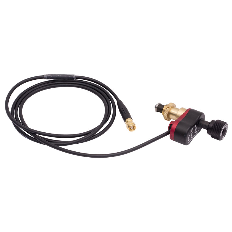 |
Piezo Inertia | 13.0 mm (0.51") | - | ≤3.6 mm/mine | - | KIM001 or KIM101 |
|
| PIA13VF | 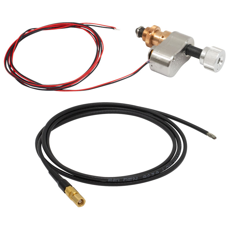 |
Piezo Inertia | 13.0 mm (0.51") | 10-6 Torr | ≤3.6 mm/mine | - | KIM001 or KIM101 |
|
| ZFS13B | 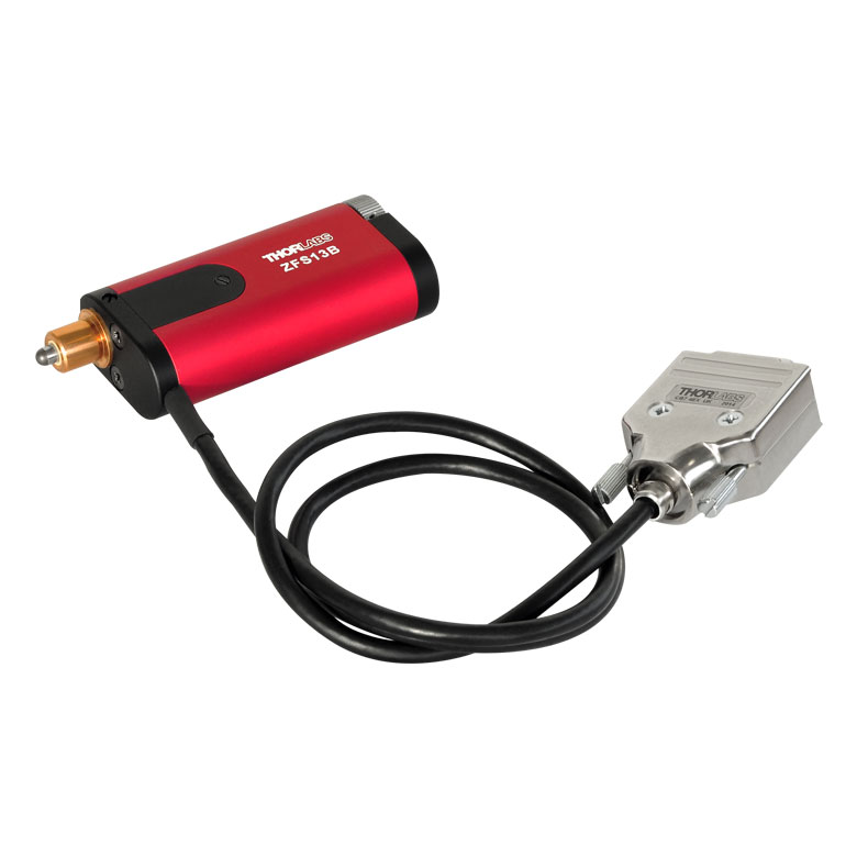 |
2-Phase Stepper Motor | 13.0 mm (0.51") | - | 2.0 mm/s | 10 mm/s2 | KST201 | |
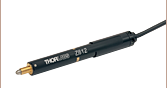
| ZST213B | 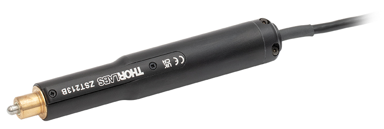 |
2-Phase Stepper Motor | 13.0 mm (0.51") | - | 2.0 mm/s | 10 mm/s2 | ||
| Z912B | 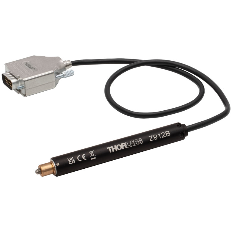 |
DC Servo Motor | 12.0 mm (0.47") | - | 2.6 mm/sf | 4 mm/s2 | KDC101 | |
| Z912BV | 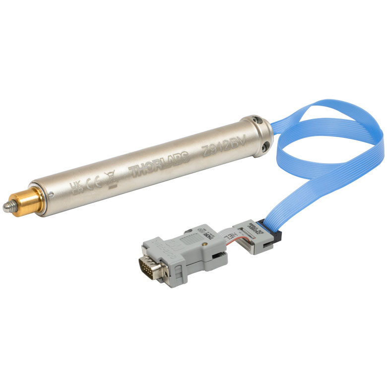 |
DC Servo Motor | 12.0 mm (0.47") | 10-6 Torr | 2.6 mm/sf | 4 mm/s2 | KDC101 | |
 Click to Enlarge
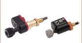
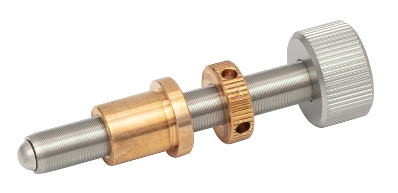
Figure G5.1 Manual Vacuum-Compatible Actuator, built using components sold below
Click to Enlarge
Figure G5.1 Manual Vacuum-Compatible Actuator, built using components sold belowThe vacuum-compatible PY004VX(/M) platform can be adjusted using our 1/2" travel actuators with Ø3/8" mounting barrels, such as the Thorlabs PIA13VF Vacuum-Compatible Piezo Inertia Actuator or Z912BV Vacuum-Compatible DC Servo Motor Actuator (sold below). Alternatively, a manual vacuum-compatible actuator can be built (See Figure G5.1), using an F25USA1 Barrel Adapter, LN25100 Lock Nut, a POLARIS-N5 Knob, and an F25US200V Vacuum Adjuster.
Note: Actuators built using 1/4"-100 vacuum adjusters are compatible with both metric and imperial stages.
| Table G5.2 Vacuum-Compatible Manual Actuatorsa | ||||||||
|---|---|---|---|---|---|---|---|---|
| 1/4"-100 Thread to Ø3/8" Barrel Adapter | 1/4"-100 Lock Nut | Knob for 1/4"-100 Adjusters | 2.00" Long 1/4"-100 Vacuum Adjuster | Vacuum Rating | ||||
| F25USA1 | LN25100 | POLARIS-N5 | F25US200V | 10-6 Torrb | ||||

 ズーム
ズーム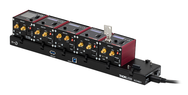 Click to Enlarge
K-Cube®モジュールの取り付けられたUSBコントローラーハブKCH601(別売り)
- 上面パネルに電動ステージやアクチュエータ制御用の速度ホイールとデジタル表示器
- 2つの双方向トリガーポート(外部機器からの信号読み取りや外部機器の制御用)
- 付属のUSBケーブルでPCに接続可能
- Kinesisソフトウェアに完全対応
- コンパクトな装置サイズ: 60.0 mm x 60.0 mm x 49.2 mm
- 電源は付属しません(下記参照)
当社のブラシ付きDCモーターコントローラK-Cube®KDC101では、1台のモータの回転軸を手動またはPCで制御できます。上面のコントロールパネルの速度ホイールを用いて、4段階の速度での前後両方向へのジョグ動作と位置のプリセットが可能です。上面パネルのデジタル表示器のバックライトは、メニューを選択することで暗くしたり消灯したりすることができます。ユニット前面には双方向性のトリガーポートが2つあり、5 Vの外部ロジック信号を読み込んだり、5 Vロジック信号を出力して外部機器を制御したりすることができます。それらの設定は、それぞれのポートごとに独立に行うことができます。
このユニットはKinesisソフトウェアパッケージに完全対応しています。 XAソフトウェアは、コントローラKDC101に対しては完全サポートしていますが、ステージPY004Z9/Mに対しては現時点ではサポートできていません。そのため、Kinesisソフトウェアパッケージをご使用いただく必要がありますのでご注意ください。XAがサポートしている製品の一覧はこちらからご覧いただけます。詳細は「Kinesisソフトウェア」タブをご参照ください。
このコントローラには電源が付属しませんのでご注意ください。対応する電源については下記の「電源」をご参照ください。詳細はDCサーボモーターコントローラKDC101の製品紹介ページをご覧ください。

 ズーム
ズーム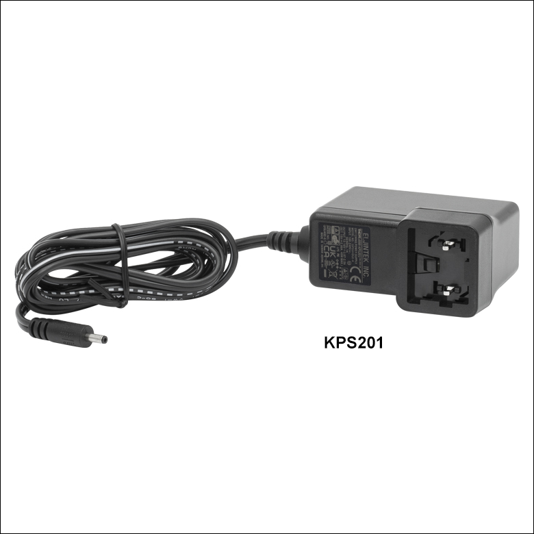
Click to Enlarge
Figure 780A 電源ユニットKPS201(日本国内向けアダプタと共に発送します)
- 電源(単体)
- KPS201: K-Cube®、T-Cubes™ 用、3.5 mmジャック付き
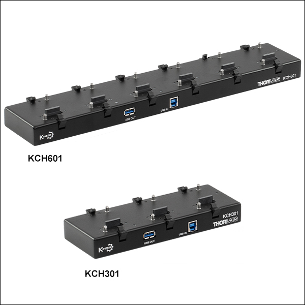
- 電源供給と通信機能を備えたUSBコントローラハブ
- KCH301: 3台までのK-CubeまたはT-Cube用
- KCH601: 6台までのK-CubeまたはT-Cube用
電源KPS201の出力電圧は+15 VDC、最大電流は2.66 Aで、3.5 mmジャックで1台のK-CubeまたはT-Cubeに電力を供給します。標準的な壁コンセントに接続して使用します。
USBコントローラーハブKCH301およびKCH601は次の2つの機能を有しています。1つはハブ機能で、最大3台(KCH301)または6台(KCH601)までのK-CubeまたはT-Cubeをサポートします。もう1つは電源機能で、標準的な壁コンセントに接続するだけで必要な電力の供給を行います。ただし、ハブが供給できる最大電流は10 Aです。お使いになる全Cubeの必要電流が合計で10 A以上にはならないことをお確かめください。 また、このハブに取り付けられたすべてのT-CubeやK-Cubeに対して、1本のUSBケーブルで接続することができます。
USBコントローラハブの詳細は、製品ページをご参照ください。

 ズーム
ズーム
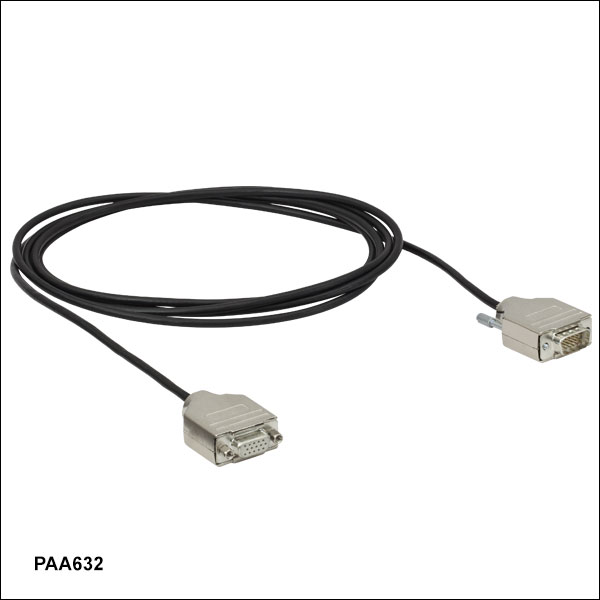
延長ケーブルPAA632の長さは2.5 mで、コネクタは当社の電動式アクチュエータ製品すべてに使用できる15ピンD‑サブコネクタです。 オス型のケーブル端はコントローラに、メス型はモータに接続します。