 Products Home
チップ、チルト&回転ステージ

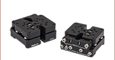
- ±5° Tip and Tilt
- ±10° Rotation
- Micrometer Positioning
Adjusts Pitch and
Roll Preload
Adjusts Yaw
Preload
TTR001SP1
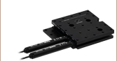
62.5 mm (2.46") Deck Height Adapter
TTR001
Provides Tip, Tilt, and Rotation
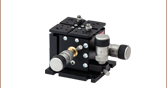
TTR001 Stage with a PM3
Clamping Arm, Holding a Prism


Please Wait
| Item # | TTR001(/M) | |
|---|---|---|
| Tip/Tilt (Pitch and Roll) Adjustment Range | ±5° | |
| Tip/Tilt (Pitch and Roll) Micrometer Resolution | 0.036° | |
| Rotation (Yaw) Adjustment Range | ±10° | |
| Rotation (Yaw) Micrometer Resolution | 0.03° | |
| Deck Height | 1.48" (37.5 mm) | |
| Deck Height with TTR001SP1(/M) Mounting Plate | 2.46" (62.5 mm) | |
| Load Capacitya,b (Max) | 11.0 lbs (5.0 kg) | |
| Construction | Aluminum | |
| Finish | Black Anodized | |
特長
- マイクロメータによるチップ、チルト、ならびに回転動作
- 12.5 mm間隔のM4タップ穴
- クランプアームPM3/M、PM4/M、PM5/Mを直接取付け可能
- デッキ高:37.5 mm
- 黒色アルマイト加工
チッ プ・チルト・回転ステージTTR001/Mは、±10°の回転(ヨー)調整と、±5°のピッチとロールの独立チルト調整が可能です。 調整によって光学部品ならびに器具が平面にアライメントされ、その後平面内で回転します。 回転軸の中心は、プラットフォームの中央に垂直な線上にあります。 チップならびにチルトの両軸は、回転軸上のステージ上面から12 mm下にあります。 上面プレートには21個のM4ネジ穴が12.5 mmの間隔で開いています。ミリ規格のステージはクランプアームPM3/M、PM4/M、PM5/Mに直接取り付けられます。
Click to Enlarge
典型的な光屈折用途に使用できるようデッキ高を上げてステージMAX311D(/M)の高さに合わせたステージTTR001(/M)。プリズムはステージに取り付けられたクランプアームPM3(/M)で保持されています。
ステージに内蔵されているMitsutoyo製の高分解能マイクロメータには10 µm毎の目盛が付いております。 マイクロメータを回すと1回転で1.5°回転(分解能:0.03°)し、1.78°チルト(分解能:0.036°)します。 上の写真で示しているマイクロメータに隣接するノブを用いて、予め負荷を調整しバックラッシュを除去することができます。 1つのノブがピッチ(Θx)ならびにロール(Θy)軸を同時に調整・固定します。もう一方のノブはヨー(Θz)軸を調整・固定します。 ノブを締め付けると、マイクロメータが緩まるまでその軸の動きは事実上固定されたままとなりますのでご注意ください。 この場合、他の軸を調整する際には摩擦が若干発生する場合があります。
ステージは標準的なM6ネジに対応する3個の貫通穴で作業面に固定されます。 ステージのデッキ高は37.5 mmです。 高さ調整プレートTTR001SP1/Mを用いてステージを標準的なデッキ高62.5 mmに上げ、当社のNanoMax、MicroBlock、ならびにRollerBlockの3軸ステージに対応可能にすることができます。 高さ調整プレートは、標準的なM6ネジに対応する3個の貫通穴を使用して作業面に固定されます。 その後、3個のM6タップ穴を使用してステージを高さ調整プレートに取り付けます。
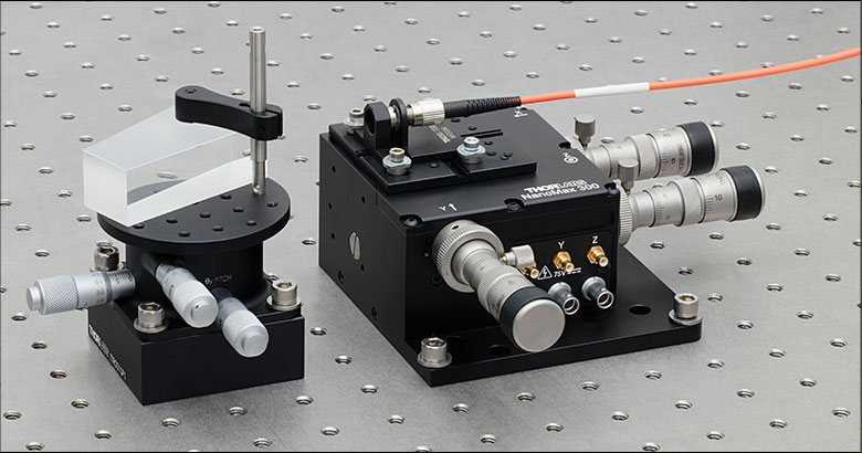
右は典型的な用途例です。TTRシリーズのステージの高さが3軸ステージMAX311D(/M)と一致するよう高さが上げられています。 ペロン・ブロカプリズムは、クランプアームPM4(/M)でチップ・チルト・回転ステージに取り付けられています。ステージMAX311D(/M)にはマウントHCS209およびファイバーホルダHFB004(旧製品)が取り付けられ、コネクタ付きファイバとコリメート用レンズを保持しています。コリメートされたビームはプリズムに入射され、マイクロメーターステージTTR001(/M)によってレーザの方向が調整されます。
| Posted Comments: | |
Andi ...
(posted 2023-04-21 06:06:05.03) Can the stage handle off center load? If yes, is there a formula to calculate the max. allowed off center load?
Thanks in advance JReeder
(posted 2023-04-24 03:29:49.0) Thank you for your enquiry. We do not have any data for the maximum off-axis load that this stage can hold. We will reach out to you to discuss your particular application. Joel Humes
(posted 2023-04-04 12:54:12.047) I am looking to attach this TTR001 (Tip, Tilt, Rotation) stage on top of a couple of LNR502E (rotary encoded stepper stages) which will actuate in X and Y directions, and all of this on top of a high load MLJ150/M (Z stage) but I am concerned with how much weight this stack will come out to.
How much does this TTR001 (Tip, Tilt, Rotation) stage weigh?
Thank you JReeder
(posted 2023-04-05 08:36:00.0) Thank you for your enquiry. The total mass of the TTR001 is 0.3 kg. I have reached out to you directly to see if you require any further information. Arthur Kenton
(posted 2022-12-12 16:50:18.333) We're trying to determine if a total of 15# load can be cantilevered about 6 inches offset from the vertical axis of the TTR1 (which has a spec of 11lbs). I have a pdf diagram I can send. do'neill
(posted 2022-12-16 06:52:34.0) Response from Daniel at Thorlabs: Thank you for your inquiry. We do not have a spec for any off-axis or cantilevered load but as your load is above even the on-axis load this will not work for your application. We will reach out to you to discuss your particular application. Aaron Schweihofer
(posted 2020-04-01 15:15:23.363) I am using Solidworks2015 and am not able to download the model, do you have an older version so I can use this part in a design? DJayasuriya
(posted 2020-04-02 05:56:46.0) Response from Dinuka at Thorlabs: Thanks for your query. I will get in touch directly to help with this issue. Thank you. WONSANG LEE
(posted 2019-12-06 00:56:16.63) Dear sir,
We have this product, TTR001/M, in our company, but θy pitch does not work now. We do not have any idea about this problem.
The micrometer head seems like stuck even though we turn it by force.
How we can solve this problem? Please give us your advice.
Thank you. cwright
(posted 2019-12-09 11:25:14.0) Response from Charles at Thorlabs: Hello Wongsang, I'm sorry to hear that you are having this issue. There are a few potential causes which require some troubleshooting so I will ask your local technical support team reach out to you directly to resolve this. emmanuel.cherin
(posted 2018-11-28 12:28:58.123) Hi,
Could the TTR001 stage could be used in a suspended, upside down position, and if it is possible what would be the maximum load (centered) ?
Thank you AManickavasagam
(posted 2018-11-29 06:55:17.0) Response from Arunthathi @ Thorlabs: Thanks for your query. The stage is only tested for the upright orientation and we would not be able to guarantee that you could achieve the specifications stated on the website when used upside down.
If you could contact techsupport directly with details of your set up (mass and momentum) we could may be replicate and test this for you. devin.metante
(posted 2016-12-10 16:15:47.343) Please provide/contact me for spec if mounted vertically. Thanks tfrisch
(posted 2016-12-19 02:07:10.0) Hello, thank you for contacting Thorlabs. TTR001/M is not intended to be mounted on a vertical surface. I will reach out to you directly with more details. Performance will likely come down to what load needs to be mounted. david.blum
(posted 2015-04-29 17:02:34.587) Hello! Is it possible to upgrade the micrometer screws on this rotation stage? How can the stock screws be dismounted? What micrometer screws would fit this stage? Thank you very much! rcapehorn
(posted 2015-04-30 10:15:31.0) Response from Rob at Thorlabs: At this moment in time we are not offering any other options of drive for this stage. Unfortunately the current drives are bonded in place, therefore they cannot be removed easily without damaging the stage. Therefore it will not be possible for you to modify this stage. rmal
(posted 2014-10-30 12:01:20.56) I was wondering why not adding, on the top of the TTR001/M, a "coarse" rotation stage. This way one could decide a rough "incidence angle" first and then adjust it using the micrometer screws. Very useful for applications where various angles are needed, but all with high degree of precision. msoulby
(posted 2014-11-03 04:01:58.0) Response from Mike at Thorlabs: Thank you for your feedback regarding this stage. I have forwarded your enquiry to the engineering team to see what would be involved in adding a rotating top plate to this stage. We will contact you directly with more details about what might be possible. xi.wang
(posted 2014-09-03 01:41:29.897) Hi Ben, we need something like this but mounted vertically with the main axis horizontal. The load (a vertical stylus or rod) will be 2 kg. When running the experiment, a horizontal force (<5N) will be applied to the stylus. Is this product able to handle this? Thank you very much. Xi bhallewell
(posted 2014-09-04 07:08:19.0) Response from Ben at Thorlabs: Thank you for your question here. As a result of previous feedback we are currently undergoing tests to spec the performance of this stage when vertically mounted. I will contact you directly to advise on your application in detail. miroslav.andrle
(posted 2014-06-19 05:02:19.583) Hello,
we're probably going to use this stage in our project but we have some trouble with enough space there so we need to try a few ways of concept to find the right fit. What i'd like to know is, if it's okay for this stage to work upside down or with the main axis in horizontal orientation.
Thank you
Best regards
M. Andrle bhallewell
(posted 2014-06-20 12:18:51.0) Response from Ben at Thorlabs: We currently do not hold load specifications for this stage when mounted vertically as the stage is designed specifically for table mounted use. I will contact you directly to discuss your requirements further. extern.marcel.liebhart
(posted 2014-06-16 16:33:59.767) Hello,
I need some informations about the Load limits for all axis (X, Y, Z, Θx, Θy, and Θz) force and moment
Thanks and Best Regards bhallewell
(posted 2014-06-18 12:25:21.0) Response from Ben at Thorlabs: We appreicate your feedback here. We spec the load capacity at 5kg on the webpage. This would account for the load limit for adjustment in dx, dy & dz (tip, tilt & rotation) only. We will contact you for further details of your requirements. rnewstrom
(posted 2013-07-08 13:39:39.16) What is the typical center of rotation for each axis on your TTR001 tip, tilt and rotation stage? cdaly
(posted 2013-07-09 10:23:00.0) Response from Chris at Thorlabs: Thank you for using our feedback tool. The rotation axis will cause movement about the line normal to the center of the platform. The tip and tilt axis will move about a point 12 mm below the top surface of the platform located on the rotation axis. |

 ズーム
ズーム
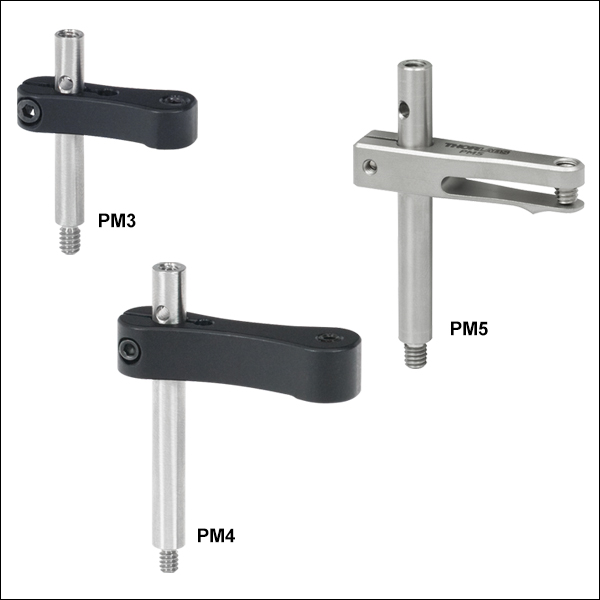
- プラットフォームマウント用のクランプ
- ポストの上部にネジ穴、下部にネジ付きスタッド
- ミリ規格製品はM4 x 0.7ネジ
- 保持できる光学素子の最大高さ:24.6 mm~41.8 mm
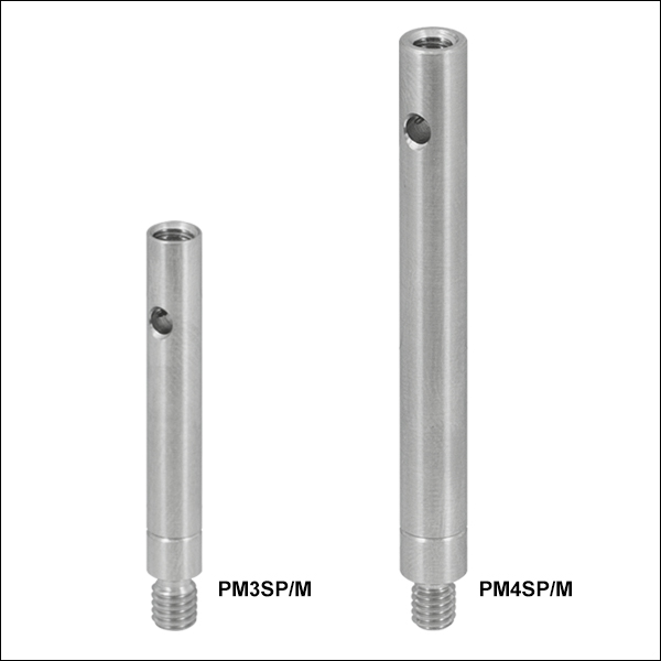
- 保持できる光学素子の高さを高くするためのエクステンションポストもご用意
- PM3SP/M + PM3/M: 高さ56.1 mmまでの光学素子を保持
- PM4SP/M + PM4/M: 高さ91.7 mmまでの光学素子を保持
Click to Enlarge
クランプアーム用エクステンションポスト、ミリ規格は溝付き
クランプアームは、当社のキネマティックプラットフォームマウント、ステージ、およびV字型クランプに光学素子を固定するためのクランプです。PM3/Mは高さ24.6 mmまでの光学素子を保持します。ポストと光学素子固定用のナイロン製先端付き止めネジとの中心間距離は17.5 mmです。PM4/Mは高さ40.9 mmまでの光学素子を保持でき、ポストとナイロン製先端付き止めネジとの中心間距離は29.3 mmです。クランプアームPM3/MおよびPM4/Mで保持できる光学素子の高さは、それぞれに対応するエクステンションポストPM3SP/MおよびPM4SP/Mを接続することで、さらに高くすることが可能です。これらのエクステンションポストは、クランプアームのセットに含まれているポストと同じものです。すべてのクランプアームにはM4 x 0.7ネジが付属します。
クランプアームPM5/Mはすべて熱処理済みのステンレススチールから製造されているため、温度変動を伴う環境中でも安定しており、また真空にも対応しています。このクランプアームはM4 x 0.7タップ穴が1つ以上あるすべてのプラットフォームマウントやステージにお使いいただけますが、特にPOLARIS-K1M4/Mと組み合わせて使用されることをお勧めしています。PM5/Mが保持できる光学素子の高さは最大41.8 mmまでで、ポスト中心から光学素子を保持する接触点までの距離は22.8 mmです。
クランプアームはすべてフレクシャー機構でポストに取付けられますが、その固定には2 mmのボールドライバや六角レンチを使用します。クランプアーム上部の止めネジで光学素子を固定する際も、2 mmのボールドライバまたは六角レンチを使用します。ポストには、ポストを締め付けるときにトルクを加えるために使用する貫通穴も付いています。その他の情報は上の図をご覧ください。