 Products Home
6軸キネマティックマウント
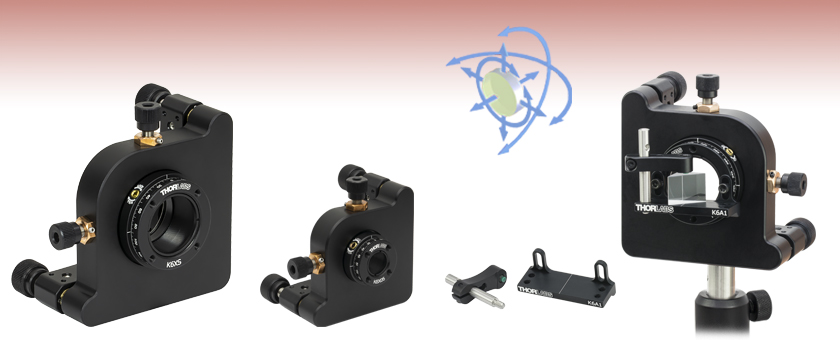
- High Precision, Locking 6-Axis Adjustment
- Mount Ø1/2", Ø1", or Ø2" Optics or
SM-Threaded Components
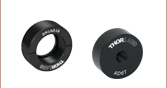
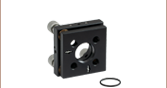
K6XS
Ø1" Optic Mount
6 Degrees of Freedom
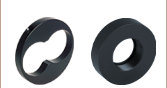
K6A1
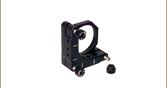
Prism Platform
for K6XS Mount
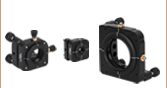
Application Idea
K6XS Mount with K6A1
Prism Mount and PS910
Right Angle Prism
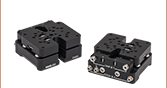
K6X05
Ø1/2" Optic
Mount


Please Wait

特長
- XYZ移動、ピッチ・ヨー調整、回転
- SM05、SM1またはSM2ネジ付き
- SM1マウントに取付けられるプリズム取付け用アタッチメントを別途ご用意
こちらのキネマティックマウントは3軸に沿った移動と、3軸周りの回転が可能です。各アジャスタには安定性を高めるために固定ネジが付いています。取付け用セルの開口部には、光学素子やSMネジ付き部品を取り付けるために、SM05、SM1またはSM2の内ネジが付いています。Ø25 mm~Ø25.4 mm(Ø1インチ)光学素子用マウントK6XSの回転ダイヤル部には、プリズムマウントK6A1/M(別売り、下記参照)を取付けるための#4-40タップ穴が4つ付いています。このプリズム取付け用アタッチメントには、12.7 mm x 42.7 mmのプラットフォームとクランプアームPM3/M、およびマウントK6XSに固定するためのネジや六角レンチが含まれています。これらのマウントは黒色アルマイト加工されています。
*こちらのマウントは、Ø12.7 mm、Ø25.4 mmまたはØ50.8 mmの光学素子に対して最適設計されています。少し小さいØ12 mm、Ø25 mm、Ø50 mmの光学素子に対してもご使用いただけますが、光学素子の偏心が重要ではない用途でのご使用をお勧めします。
Click to Enlarge
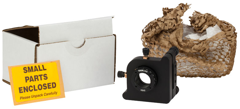
Figure 2.1 K6XS Packaging

Smart Pack Goals
- Reduce Weight of Packaging
- Increase Usage of Recyclable Materials
- Improve Packing Integrity
- Decrease Shipping Costs
Thorlabs' Smart Pack Initiative is aimed at minimizing waste while providing adequate protection for our products. By eliminating any unnecessary packaging, implementing design changes, and utilizing eco-friendly materials, this initiative seeks to reduce the environmental impact of our product packaging.
The updated K6XS packaging primarily consists of recycled paper and cardboard and weighs 64% less than the original packaging. This weight change results in a 75% reduction in CO2 emissions per year, based on typical product sales.
As we move through our product line, we will indicate re-engineered, eco-friendly packaging with our Smart Pack logo.
| Posted Comments: | |
Steven yao
(posted 2024-10-11 01:57:11.043) Hello, I would like to inquire about a product for experimentation, model K6XS.
On the model, the three adjustment screws for pitch and Z-axis are not equipped with locking screws. I have two questions here. Question one: How do I lock the three adjustment screws mentioned above? Question 2: Can you provide stability data or proof for this product?
Thank you, have a nice day. jdelia
(posted 2024-10-11 04:51:00.0) Thank you for contacting Thorlabs. The K6XS has a locking screw located near each one of its adjusters. While I have reached out to you directly via email to share a screenshot with these screws called out, you can also find them called out in the CAD drawing: https://www.thorlabschina.cn/_sd.cfm?fileName=TTN009762-E0W.pdf&partNumber=K6XS. We unfortunately have not taken any long-term stability data for these mounts. Leonardo Scarabelli
(posted 2024-09-20 16:08:23.58) Could I mount a 2inch OAP on a K6X2?
I guess I don't understand the limitation on the optic's thickness indicated in the table (Max
Optic Thickness). Thank you! EGies
(posted 2024-09-27 02:18:29.0) Thank you for contacting Thorlabs. You would not be able to directly mount a 2" OAP in a K6X2. The K6X2 secures an optic by its edges between a retaining lip and a threaded retaining ring. The maximum thickness spec refers to the maximum edge thickness of the optic that can physically fit between the lip and the retaining ring. In order to mount one of our 2" OAP mirrors into the K6X2, you would need to use a mounting adapter like the SM2MP, which has external SM2 threads that fit in the K6X2's internal SM2 threads: https://www.thorlabs.com/thorproduct.cfm?partnumber=SM2MP. Giulia Zanini
(posted 2024-07-09 10:51:59.207) Which differential adjusters can be used to replace the current tip/tilt adjusters of the K6XS? Thank you! jdelia
(posted 2024-07-09 02:44:24.0) Thank you for contacting Thorlabs. We unfortunately do not offer any differential adjusters compatible with the K6XS mount at this time. We apologize for the inconvenience. Francois Laforge
(posted 2022-11-29 14:46:26.83) Even with the lock screw completely unlocked, the rotation force necessary to manually rotate the mount is too strong. I can I loosen the mount so that it is easier to rotate? jdelia
(posted 2022-12-27 08:50:53.0) Thank you for contacting Thorlabs. This mount should not be very difficult to rotate. I have reached out to you directly in an attempt to troubleshoot and resolve your issue. Sean Kung
(posted 2021-10-14 01:46:04.13) Hi, I work in the University of British Columbia. Is this item (K6X05) rough vacuum compatible (~10^-3 Torr)? We are looking for a compact (3x3x3 inches) 6-axis mount as our sample stage in a FTIR spectrometer. Thanks! azandani
(posted 2021-10-15 04:41:10.0) Hello Sean, thank you for contacting Thorlabs. Unfortunately, this item is not vacuum compatible (~10^-3 Torr). We do not recommend placing anodized parts into a vacuum chamber as the surface of an anodized component is porous and can become contaminated. That being said, I will reach out to you directly to discuss the feasibility of a custom option. Zheng Xiang
(posted 2020-10-02 10:17:47.62) 为什么K6XS的安装孔没有螺纹?我用对应的8-32(M4)的TRA75/M不适配。急需答复!谢谢! YLohia
(posted 2020-10-02 09:48:59.0) The K6XS is specified to have two #8 (M4) counterbored holes, not threaded holes, for mounting. You will have to use capscrews (not setscrews) to mount this to a post. https://www.thorlabs.com/_sd.cfm?fileName=TTN009762-E0W.pdf&partNumber=K6XS mdelgrange
(posted 2019-02-04 09:05:59.12) Hi,
Do you have a solution for having a K6XS compatible with a 60mm cage system ?
Thank you. llamb
(posted 2019-02-05 08:17:11.0) Thank you for contacting Thorlabs. The K6XS currently does not have enough space to accommodate holes for a 60 mm cage system. I have reached out to you directly to discuss your application and possible configurations. akuznetsov
(posted 2018-07-02 22:16:49.88) Who designed the 8/32 mounting points to be spaced apart at 0.395" and 0.55"? Completely doesn't match imperial breadboard hole patterns for 2 screw attachment. Yes the corner hole can't be too far from the center line because of the corner, but the outer edge hole could have at least been 1" away from the corner hole. Instead of 0.55" center to edge, it should have been 0.605" that way corner to edge holes would provide 1" mounting space, and while that would make the center line off axis, frankly I con't care and those who do can use a translation stage or just use 1 screw in the first place. llamb
(posted 2018-07-09 09:56:11.0) Thank you for your feedback. I have added this suggestion to our internal product forum for further revision. The original design was limited by space constraints on the back plate of the mount between the springs and adjuster screw. For two screw attachment, you can still mount two posts to the K6XS and place them in our more versatile Universal Post Holders, so the hole spacing will not limit you for breadboard mounting. I will reach out to you directly in case you are interested in a custom product. jchapmn2
(posted 2015-07-13 11:07:49.257) Hello, in your older model, "K6X", you had four holes tapped on the back side for 30mm cage system. It was not very useful because the back plate was in the way of getting the cage component really close to the front plate and if you wanted them close you had to screw it into the back side of the front plate where there is no x/y translation. I STRONGLY suggest putting tapped holes on the front side for a 30mm cage system so that you can bring cage compenents really close to the front where something could be mounted and have x/y translation.
We like to use the cage rods on the back side of the old ones to do fiber coupling with a mounted asphere and a connectorized fiber mounted in one of your terminating plates. Your collimation packages are great but sometimes you need other focal lengths and greater positioning control and if you can have the fiber and lens on a cage mount together it greatly increases stability. And having that mounted on a K6XS allows you to tilt the whole system together which is necessary for high coupling efficiency. besembeson
(posted 2015-09-23 11:17:21.0) Response from Bweh at Thorlabs USA: In the current design, one way to achieve this is to use a cage plate like the CP02 with a coupler such as SM1T2 or SM1T10. It seems it makes sense to include the 30mm cage holes to the front mounting surface but this will involve a redesign at this time. Klaus.Bergner
(posted 2014-06-19 02:35:13.12) Hello Thorlabs - team,
would it be possible to add 3 additional holes in this mount to use it with a cage system?
Kind regards from Jena, Germany,
Klaus Bergner jlow
(posted 2014-08-01 04:41:25.0) Response from Jeremy at Thorlabs: The K6XS is not suitable for cage system. However, you should be able to achieve similar functionality using a combination of other kinematic and rotation mounts. We will contact you to get more details on your application and suggest appropriate items. andreas.olk
(posted 2014-04-22 12:17:27.203) Dear Sir or Madam,
is there a way to mount a BB2-E03 Ø2" Broadband Dielectric Mirror on the K6XS?
Kind regards,
Andreas Olk
-------------------------------------------------
Andreas Olk
Optische Systeme
Optical Systems
Fraunhofer-Institut für Lasertechnik ILT
Steinbachstr. 15, 52074 Aachen, Germany
Tel +49 241 8906-8082
Fax +49 241 8906-121
andreas.olk@ilt.fraunhofer.de
http://www.ilt.fraunhofer.de
-------------------------------------------------
Besuchen Sie uns/Visit us:
AKL'14 - International Laser Technology Congress
07.-09. Mai 2014, Aachen
Eurogress Conference Center
www.lasercongress.org jlow
(posted 2014-04-22 09:08:17.0) Response from Jeremy at Thorlabs: You can do this using two adapters: SM1A2 and SM2P2. You can find them at the following links.
SM1A2: http://www.thorlabs.com/thorproduct.cfm?partnumber=SM1A2
SM2P2: http://www.thorlabs.com/newgrouppage9.cfm?objectgroup_id=748&pn=SM2P2 jlow
(posted 2012-08-02 14:53:00.0) Response from Thorlabs: There should always be some clearance between the mount and the circular bore. I will get in contact with you directly regarding sending your K6X back to us to be inspected/repaired. christopher.long
(posted 2012-07-27 08:08:28.0) It seems like the xy translation is limited because of the circular opening surrounding the inner mount. I often bump into edges when trying to align a fiber. Any thoughts on changing to a square shape so that we can reach the corners? Thanks! tcohen
(posted 2012-04-02 17:29:00.0) Update from Tim at Thorlabs: There is a possibility of rotation to occur when the X and Y axis is adjusted. We are testing the current K6X to determine where the rotation is coming from and how to redesign to correct for this. Thank you for your feedback to help us create a better product for future users! bdada
(posted 2012-03-29 16:29:00.0) Response from Buki at Thorlabs:
Thank you for your feedback on the K6X mount. We are reviewing your comments and suggestions and will post an update shortly on our plans to improve the performance of this product. user
(posted 2012-03-27 11:22:41.0) Terrible mount, the rotation DOF creeps. If you mount an optical fiber + collimator to this mount, the rotational DOF about the collimator optical axis creeps because of little friction. You cannot maintain any alignment, forget about polarization orientation. Increasing the friction will not fix the problem. Unless you fix this issue by adding a lock screw you should recall this product. bdada
(posted 2012-01-25 20:32:00.0) Response from Buki at Thorlabs:
Thank you for your response. You cannot lock the rotation of the K6X. Please use the link below to consider some of our lockable rotation mounts:
http://www.thorlabs.com/NewGroupPage9.cfm?ObjectGroup_ID=1885
Depending on your application, we may be able to combine multiple products to get you the rotation and kinematic adjustment you need. We will contact you to continue this discussion. rbjaculbia
(posted 2012-01-24 00:12:35.0) Hi, Is it possible to lock the rotation of the k6x? thank you bdada
(posted 2011-11-22 13:02:00.0) Response from Buki at Thorlabs:
Thank you so much for your feedback. We apologize you could not quickly find all relevant information about the K6X. The SM1 thread is 1.035"-40. This information is on the drawing but we are already working on including this information in the web presentation on this page and across our website to make it easier to identify the Thorlabs threads we use.
Thank you again for your feedback. We have contacted you to provide additional support, but please contact TechSupport@thorlabs.com if you have any questions. volkov
(posted 2011-11-22 06:08:20.0) Terrible.
I spent hours both with catalogue and with your website trying to understand what is the thread of this mount (not a thread for mounting on post): the thread to mount optical components with it.
Still I do not see any clear number. bdada
(posted 2011-10-21 13:59:00.0) Response from Buki at Thorlabs:
Thank you for your feedback. We just released XY cage translators that provide translation without the optic cell rotating. Please refer to the link below to get more information about the CXY1 and CXY2. We are working on incorporating this design into the rest of our lens translators. Please contact TechSupport@thorlabs if you have any questions.
http://www.thorlabs.com/NewGroupPage9.cfm?ObjectGroup_ID=184&pn=CXY1#3042 jjurado
(posted 2011-09-01 11:51:00.0) Response from Javier at Thorlabs to schaefer: The tip and tilt capability of the K6X mount should help in increasing the coupling efficiency of your system. However, there are other parameters that are also important such as the operating wavelength, the type of fiber used with the F810SMA-780, and the mechanics used to mount this fixed collimator. I will contact you directly to get more information about your experimental setup. schaefer
(posted 2011-08-31 15:42:14.0) Hi,
I use a HPSC10 fiber in combination with the reflective collimator (RC08FC-P01) to create a ray of light with very low divergence. The collimator is mounted on a 60mm cage (using CP1XY and an adapter from 30 ro 60mm cage). Can I use K6X to align the collimator in order to use F810SMA-780 to couple the light back into a fiber? It seems as if the thread of CP1XY isnt precise enough to allign the ray. bdada
(posted 2011-08-25 11:31:00.0) Response from Buki at Thorlabs:
The outer diameter for the X-Y adjustment knob is Ø0.28 and the tip/tilt adjustment knob is Ø0.58". kmmertes
(posted 2011-08-22 16:20:55.0) I need to connect flexible drive shafts to the X,Y, Pitch and Yaw adjustment screws heads. What is the OD of the X-Y adjustment screw heads and the OD of the pitch and yaw adjustment screw heads? Thanks. tor
(posted 2010-11-15 15:01:43.0) A response from Tor at Thorlabs to rbjaculbia: Thank you for your inquiry. Our Mechanics Department indicates that translation in the x- and y-axes will introduce ~2° of rotation. Please note that this can be easily corrected after adjustments in x- and y-axes are made. rbjaculbia
(posted 2010-11-14 21:22:10.0) hi, how much rotation does the k6x introduce to the optic? Thanks apalmentieri
(posted 2010-02-10 14:09:15.0) A response from Adam at Thorlabs to blair: The weight of the K6X is 1lbs. At this time, we do not offer a cheaper four axis kinematic mount. Thank you for the idea and I will contact you directly to get more information about the price you were looking for. blair
(posted 2010-02-10 10:38:53.0) Hello,
I couldnt find the weight of your unit. We want to use it on a motorized stage and interested in the weight due to limits of our stage. Also, do you offer a cheaper four-axis mount? I just want tilt and XY. Greg
(posted 2009-03-10 08:47:04.0) A response from Greg at Thorlabs to marshabr: Thank you for your feedback regarding our products. We always like to hear our customers suggestions as customer centricity is at the heart of our company. I am sorry that our K6X mount is not suitable for your application. If you would like, I can have a member of our RMA staff issue a return on these for you. I will also let our Mechanics department that customers, like you, require a 6-Axis mount with completely independent axis adjustment. I updated the webpage to reflect the X- and Y-axis issue you mention. marshabr
(posted 2009-03-06 16:58:49.0) I purchased two of the K6X mounts. They are not usable for my application because the translation mechanism is inherently coupled to rotation due to the design. When the positioner translates, the moving part pivots about the spring and visibly rotates, meaning that alignment will have to be iterative. This is a very poor design for translation, but it is simple and cheap. I will have to purchase from another vendor that makes a similar device with a good translation stage. I will have to find a use for these mounts in a less demanding application.
You really should point out this problem in the description. Tyler
(posted 2008-10-03 08:28:16.0) A response from Tyler at Thorlabs to jian.wang: Your idea has been entered into our internal engineering forum along with your contact information. Although not all ideas entered into the forum make it to the development stage, we always appreciate suggestions that come from the field. I will personally solicit the attention of an engineer to look at this idea. If the idea is adopted, we traditionally involve the originator of the the idea in the design stage as well provide them with preproduction models, in so much as they want to be involved. Thank you for your contribution. jian.wang
(posted 2008-10-01 07:22:30.0) Dear Sir/Madam
It would be a popular good source or detector mount for your cage system, if a cage system compatible new product of functions similar to the "K6X 6-Axis Kinematic Optic Mount" can be made availabe.
Regards
Dr. J Wang
ASG,NPL,UK Tyler
(posted 2008-09-04 17:32:16.0) A response from Tyler at Thorlabs to r96222041: This depends somewhat on how the device is mounted. However, we tested a K6X by hanging a mass 25 mm off of the front plate of the K6X. The mount functioned correctly for masses up to 330 grams. For heavier masses the springs were not stiff enough for the mount to function properly. We are always interested in hearing about the types of products our customers need for their applications. If you could provide us with more information about your application perhaps we could suggest an alternative solution or develop a product that would be suitable for your needs. Thank you for your interest in our products. r96222041
(posted 2008-09-04 12:55:00.0) I was wondering that how much weight can this K6X mount support? I want to mount a 700-gram device on it and I am afraid that is too much for this mount.
Thanks for your reply. |
回転マウント&回転ステージのセレクションガイド
当社では手動式および電動式の回転マウントと回転ステージを豊富にご用意しております。回転マウントの内孔はØ12 mm~Ø12.7 mm(Ø1/2インチ)、Ø25 mm~Ø25.4 mm(Ø1インチ)、またはØ50 mm~Ø50.8 mm(Ø2インチ) の光学素子取付け用に設計されております*。また回転ステージには、様々な部品やシステムが取り付けられるようにタップ穴が配置されております。電動式は、DCサーボモータ、2相ステッピングモータ、あるいはElliptec™共振ピエゾモータにより駆動されます。いずれも360°の連続回転が可能です。
*下表のマウントは、Ø12.7 mm、Ø25.4 mm、Ø50.8 mmの光学素子に対して最適設計されています。Ø12.0 mm、Ø25.0 mm、Ø50.0 mmなどの少し小さい光学素子に対してもご使用いただけますが、光学素子の偏心が重要ではない用途でのご使用をお勧めします。
手動回転マウント
| Rotation Mounts for Ø1/2" Optics | |||||||
|---|---|---|---|---|---|---|---|
| Item # | MRM05(/M) | RSP05(/M) | CRM05 | PRM05(/M)a | SRM05 | KS05RS | CT104 |
| Click Photo to Enlarge | 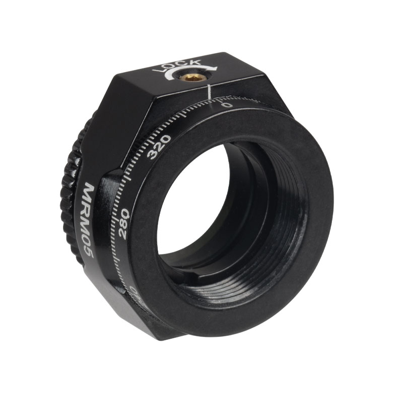 | 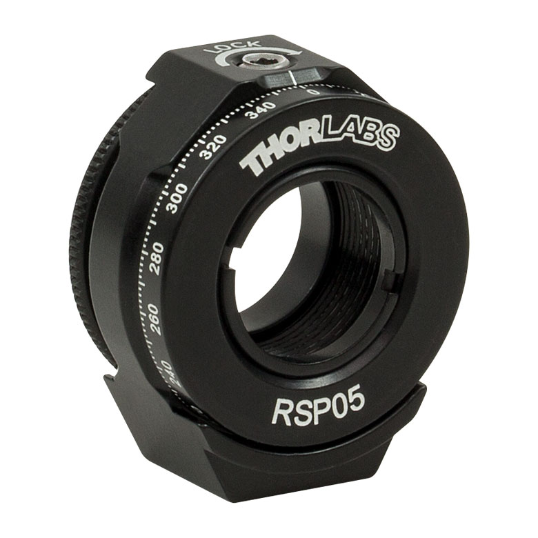 | 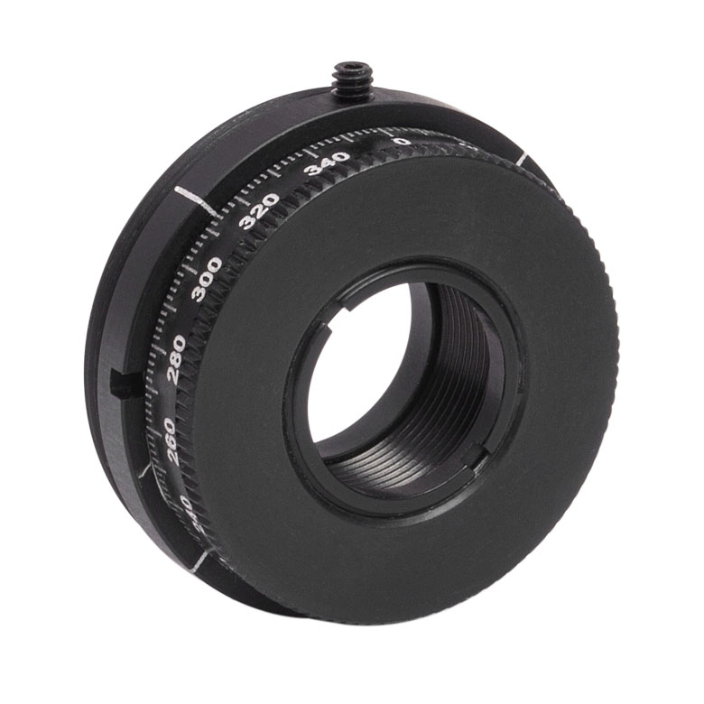 | 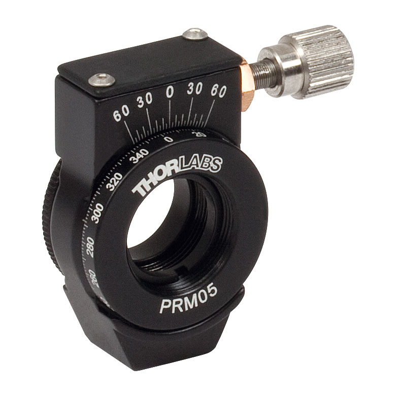 | 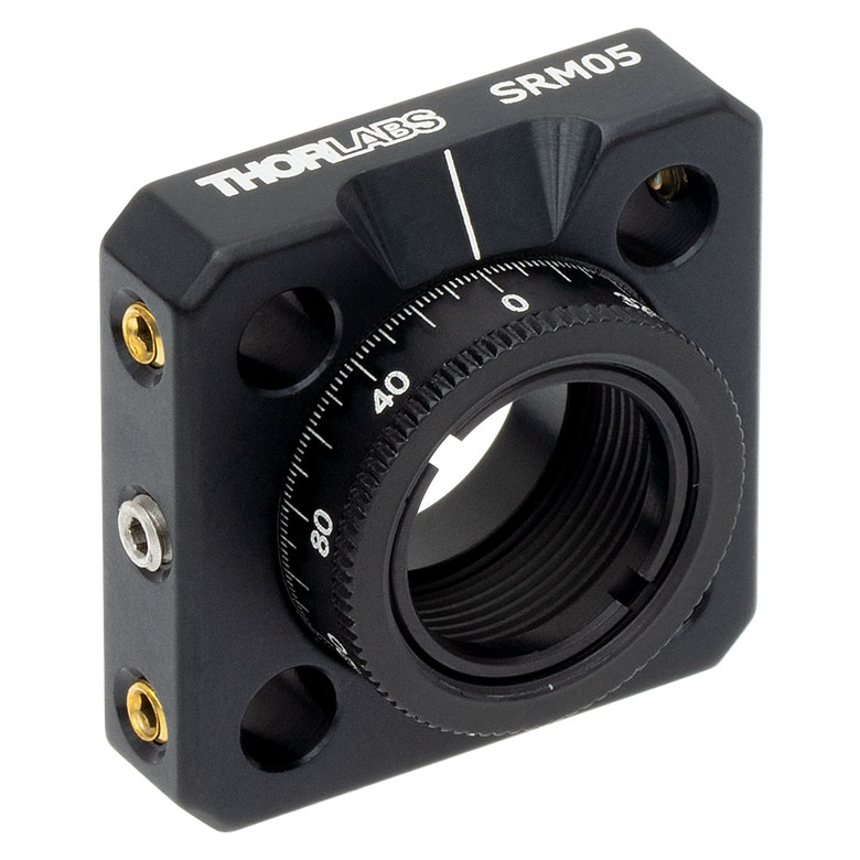 | 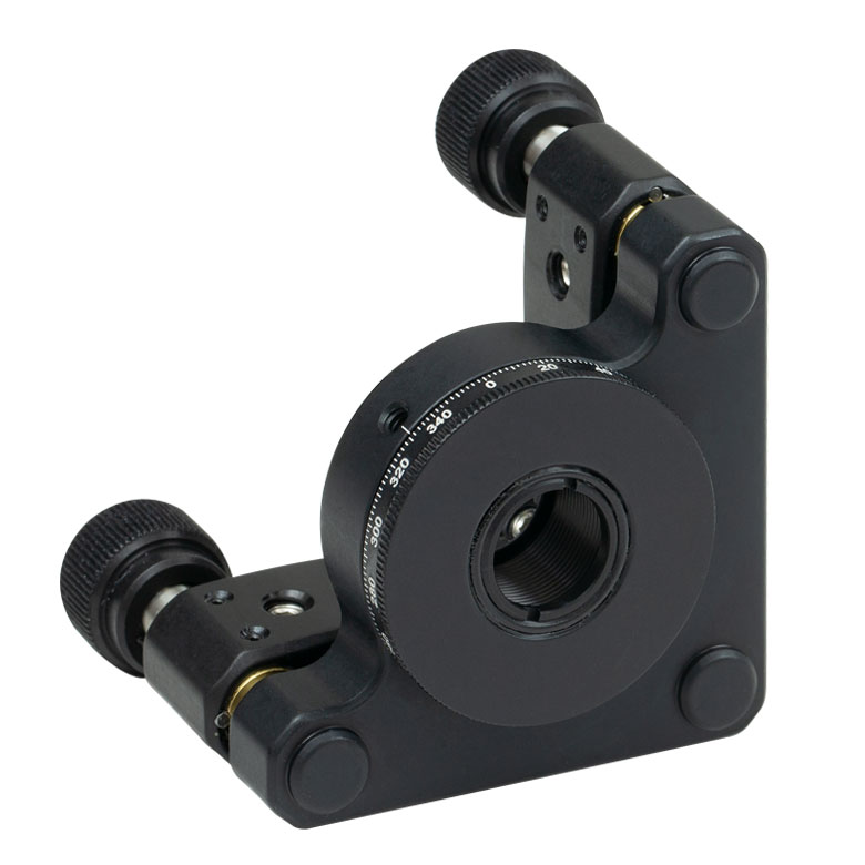 |  |
| Features | Mini Series | Standard | External SM1 (1.035"-40) Threads | Micrometer | 16 mm Cage-Compatible | ±4° Kinematic Tip/Tilt Adjustment Plus Rotation | Compatible with 30 mm Cage Translation Stages and 1/4" Translation Stagesb |
| Additional Details | |||||||
| Rotation Mounts for Ø1" Optics | ||||||||
|---|---|---|---|---|---|---|---|---|
| Item # | RSP1(/M) | LRM1 | RSP1D(/M) | DLM1(/M) | CLR1(/M) | RSP1X15(/M) | RSP1X225(/M) | PRM1(/M)a |
| Click Photo to Enlarge | 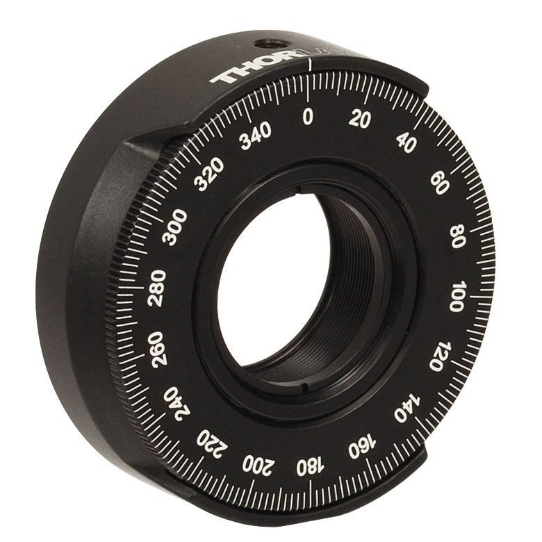 | 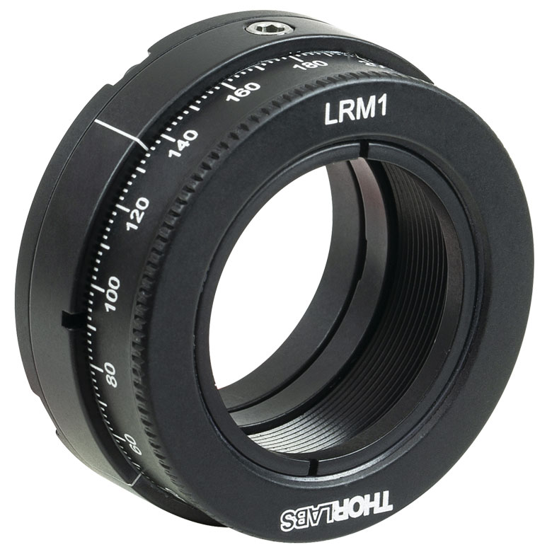 | 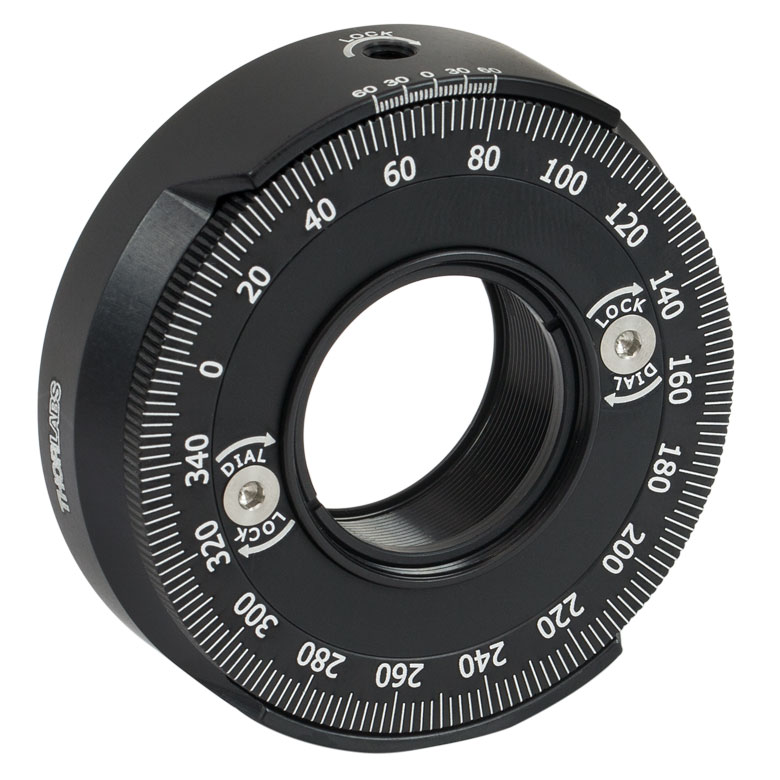 | 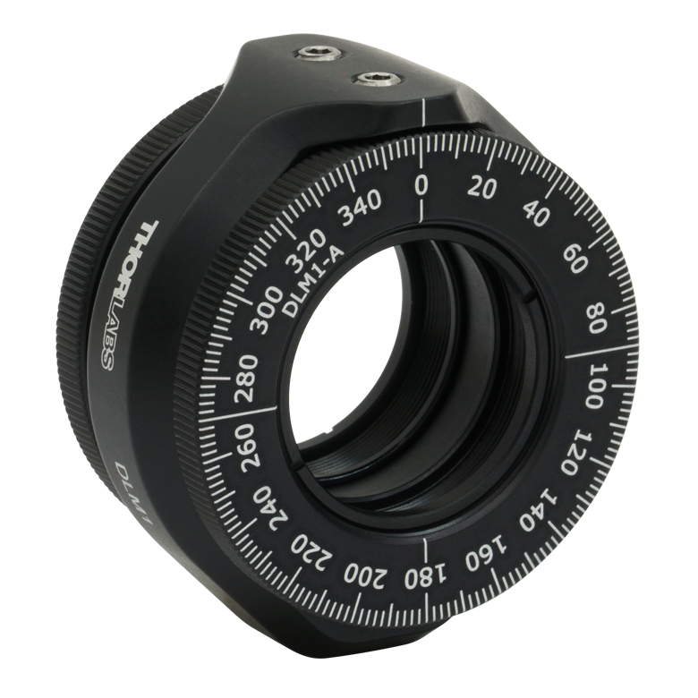 | 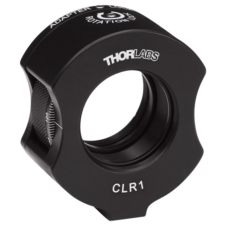 | 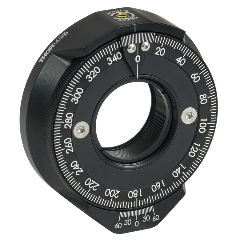 | | 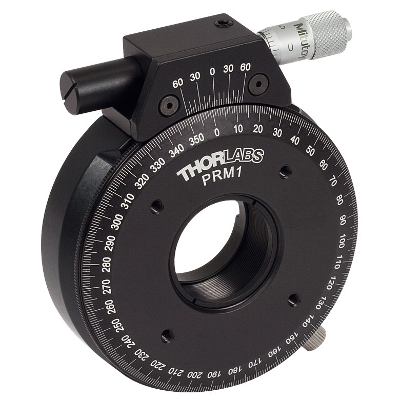 |
| Features | Standard | External SM1 (1.035"-40) Threads | Adjustable Zero | Two Independently Rotating Carriages | Rotates Optic Within Fixed Lens Tube System | Continuous 360° Rotation or 15° Increments | Continuous 360° Rotation or 22.5° Increments | Micrometer |
| Additional Details | ||||||||
| Rotation Mounts for Ø1" Optics | ||||||
|---|---|---|---|---|---|---|
| Item # | LM1-A & LM1-B(/M) | CRM1T(/M) | CRM1LT(/M) | CRM1PT(/M) | KS1RS | K6XS |
| Click Photo to Enlarge | 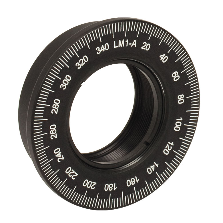 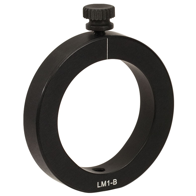 | 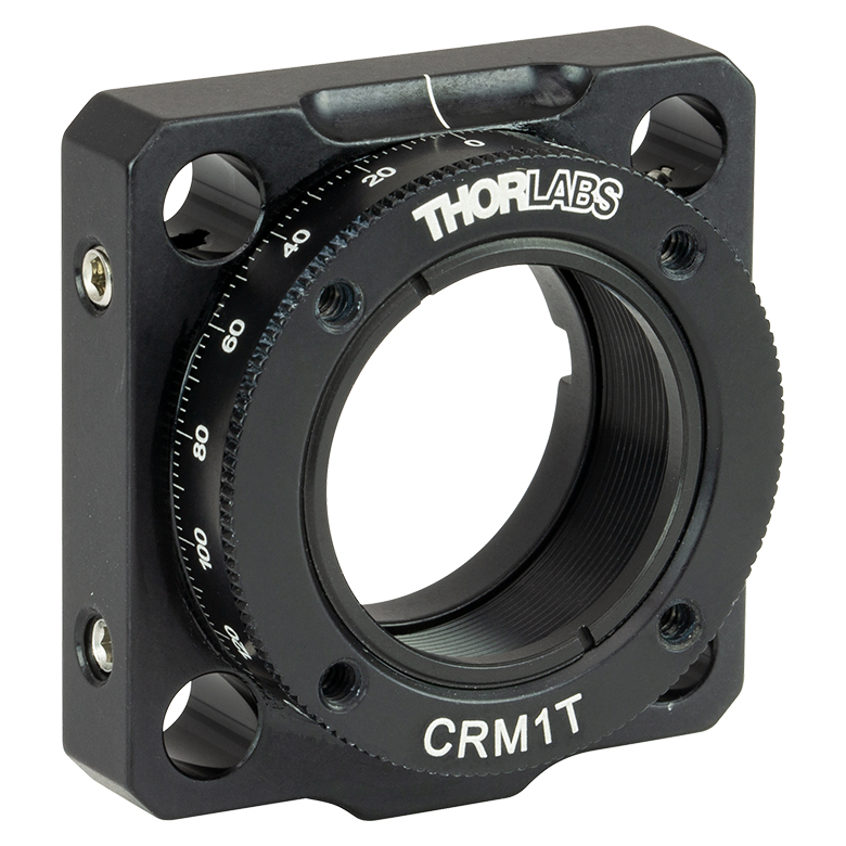 |  |  | 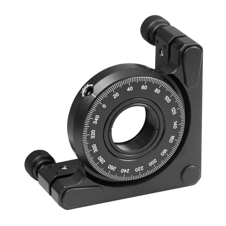 | 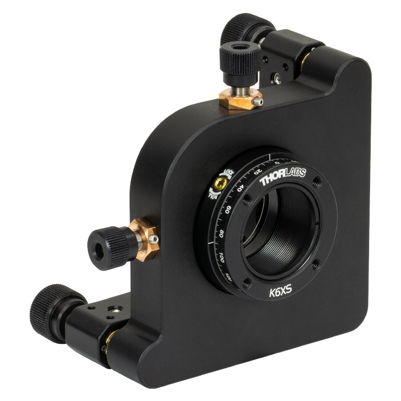 |
| Features | Optic Carriage Rotates Within Mounting Ring | 30 mm Cage-Compatiblea | 30 mm Cage-Compatible for Thick Opticsa | 30 mm Cage-Compatible with Micrometera | ±4° Kinematic Tip/Tilt Adjustment Plus Rotation | Six-Axis Kinematic Mounta |
| Additional Details | ||||||
| Rotation Mounts for Ø2" Optics | |||||||
|---|---|---|---|---|---|---|---|
| Item # | RSP2(/M) | RSP2D(/M) | PRM2(/M) | LM2-A & LM2-B(/M) | LCRM2A(/M) | KS2RS | K6X2 |
| Click Photo to Enlarge |  |  | 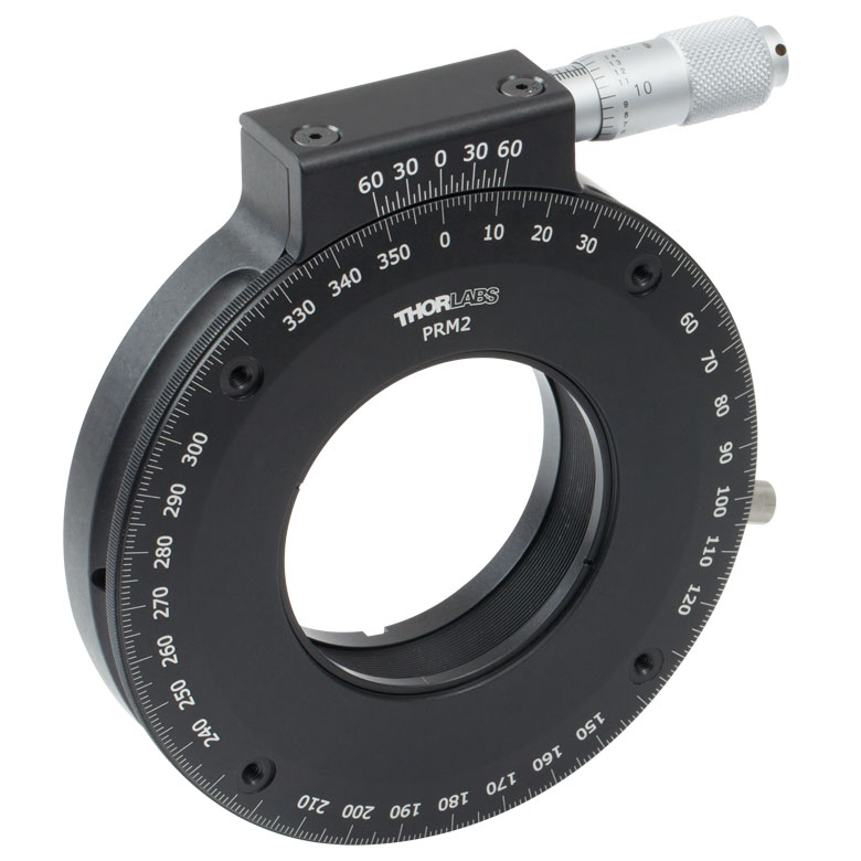 | 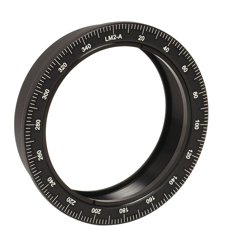 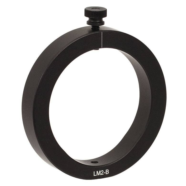 |  |  | 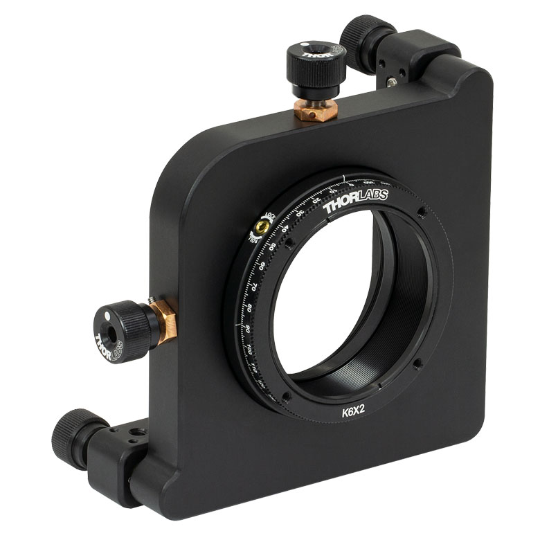 |
| Features | Standard | Adjustable Zero | Micrometer | Optic Carriage Rotates Within Mounting Ring | 60 mm Cage-Compatible | ±4° Kinematic Tip/Tilt Adjustment Plus Rotation | Six-Axis Kinematic Mount |
| Additional Details | |||||||
| Rotation Drive Mechanism and Adjustment Range | Manual, 360° Continuous | Coarse: Manual, 360° Continuous; Fine: ±7° Micrometer | Manual, 360° Continuous | ||||
| Optic Mounting | Internally SM2-Threaded Carriage | Internal SM2 Threads in LM2-A | Internally SM2-Threaded Carriage | ||||
| Maximum Accepted Optic Thickness | 0.51" (13 mm) | 0.54" (13.7 mm) | 0.48" (12.2 mm) | 0.46" (11.7 mm) | 0.52" (13.2 mm) | 0.47" (12 mm) | 0.53" (13.4 mm) |
| Post Mounting | 8-32 (M4) Tap | 8-32 (M4) Tap in LM2-B | 8-32 (M4) Tap | Four Counterbores for 8-32 (M4) Cap Screws | Six Counterbores for 8-32 (M4) Cap Screws | ||
| Cage System Compatibility | N/A | Four 4-40 (M3) Taps on Rotation Dial with 60 mm Spacing | N/A | Four Bores for Ø6 mm Cage Rods with 60 mm Spacing | N/A | N/A | |
手動回転ステージ
| Manual Rotation Stages | ||||||
|---|---|---|---|---|---|---|
| Item # | RP005(/M) | PR005(/M) | MSRP01(/M) | RP01(/M) | RP03(/M) | QRP02(/M) |
| Click Photo to Enlarge |  |  |  |  | 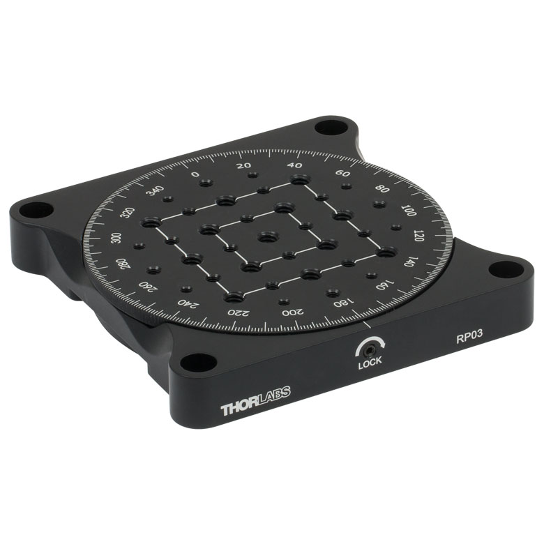 | 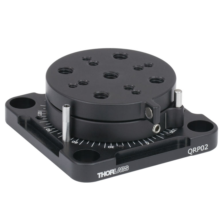 |
| Features | Standard | Two Hard Stops | ||||
| Additional Details | ||||||
| Manual Rotation Stages | ||||||
|---|---|---|---|---|---|---|
| Item # | XRNR1(/M) | XRR1(/M) | PR01(/M) | CR1(/M) | XYR1(/M) | OCT-XYR1(/M) |
| Click Photo to Enlarge | 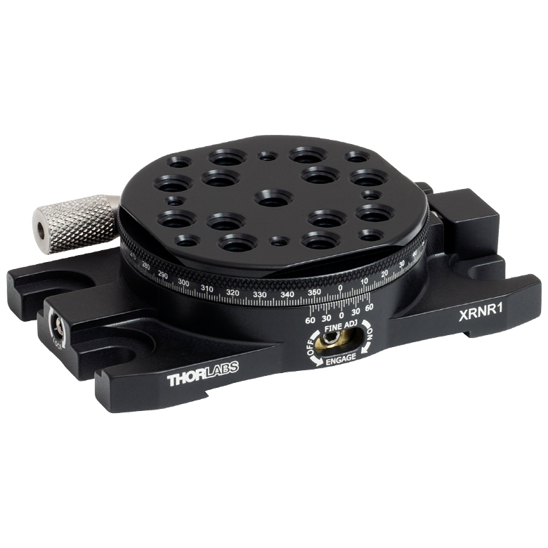 |  | 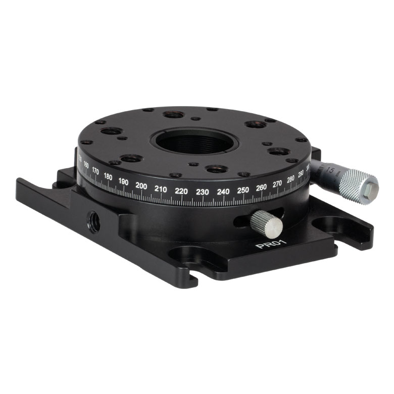 | 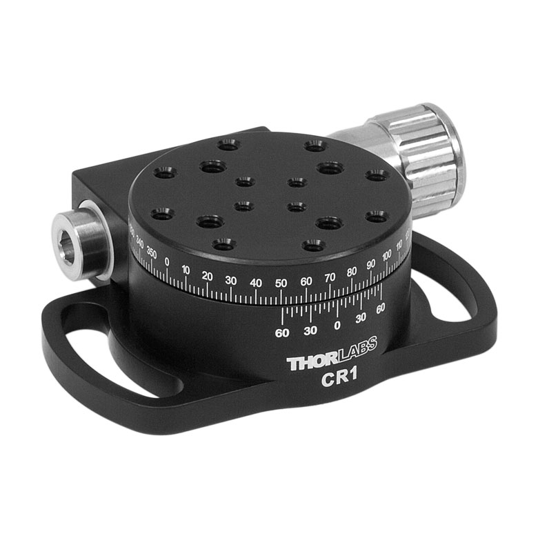 | 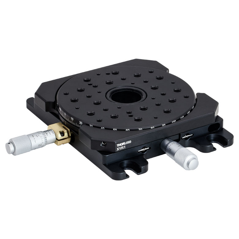 | 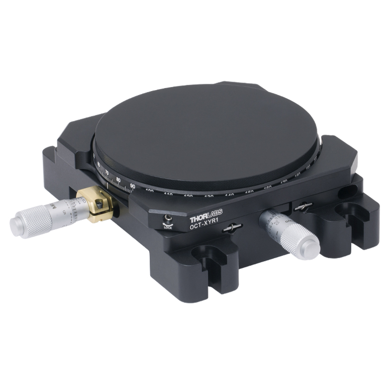 |
| Features | Fine Rotation Adjuster and 2" Wide Dovetail Quick Connect | Fine Rotation Adjuster and 3" Wide Dovetail Quick Connect | Fine Rotation Adjuster and SM1-Threaded Central Aperture | Fine Pitch Worm Gear | Rotation and 1/2" Linear XY Translation | |
| Additional Details | ||||||
電動回転マウント&ステージ
| Motorized Rotation Mounts and Stages with Central Clear Apertures | |||||
|---|---|---|---|---|---|
| Item # | DDR25(/M) | PDR1C(/M) | PDR1(/M) | PDR1V(/M) | PDXR1(/M) |
| Click Photo to Enlarge | 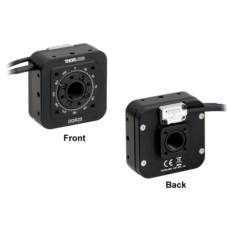 | 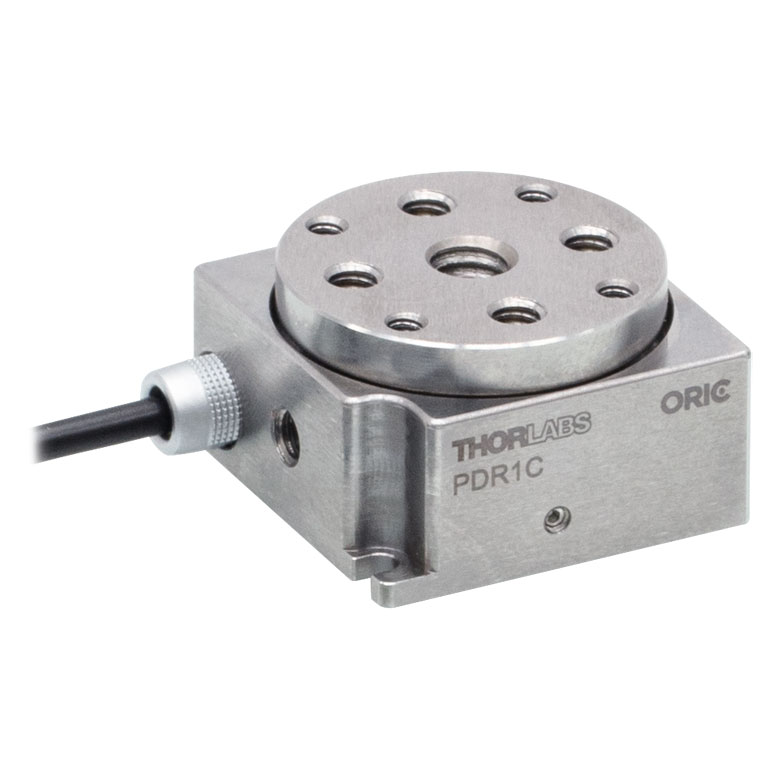 | 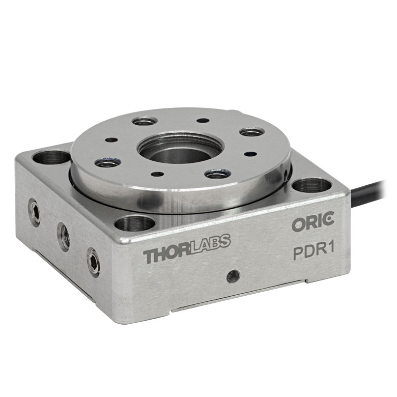 |  |  |
| Features | Compatible with SM05 Lens Tubes, 16 mm Cage System, & 30 mm Cage System | Compatible with 16 mm Cage System | Compatible with SM05 Lens Tubes & 30 mm Cage System | Vacuum-Compatible; Also Compatible with SM05 Lens Tubes & 30 mm Cage System | Compatible with SM05 Lens Tubes & 30 mm Cage System |
| Additional Details | |||||
| Motorized Rotation Mounts and Stages with Central Clear Apertures | |||||||
|---|---|---|---|---|---|---|---|
| Item # | K10CR1(/M) | PRM1Z8(/M)a | DDR100(/M) | ELL16 | ELL14 | ELL21(/M) | HDR50(/M) |
| Click Photo to Enlarge | 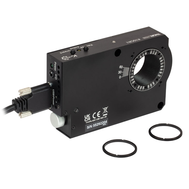 | 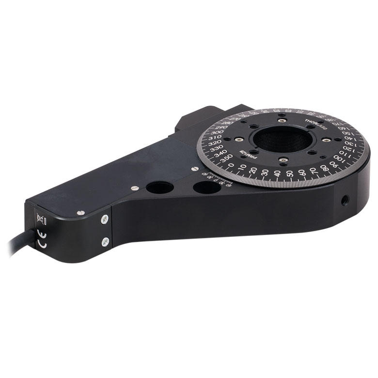 | 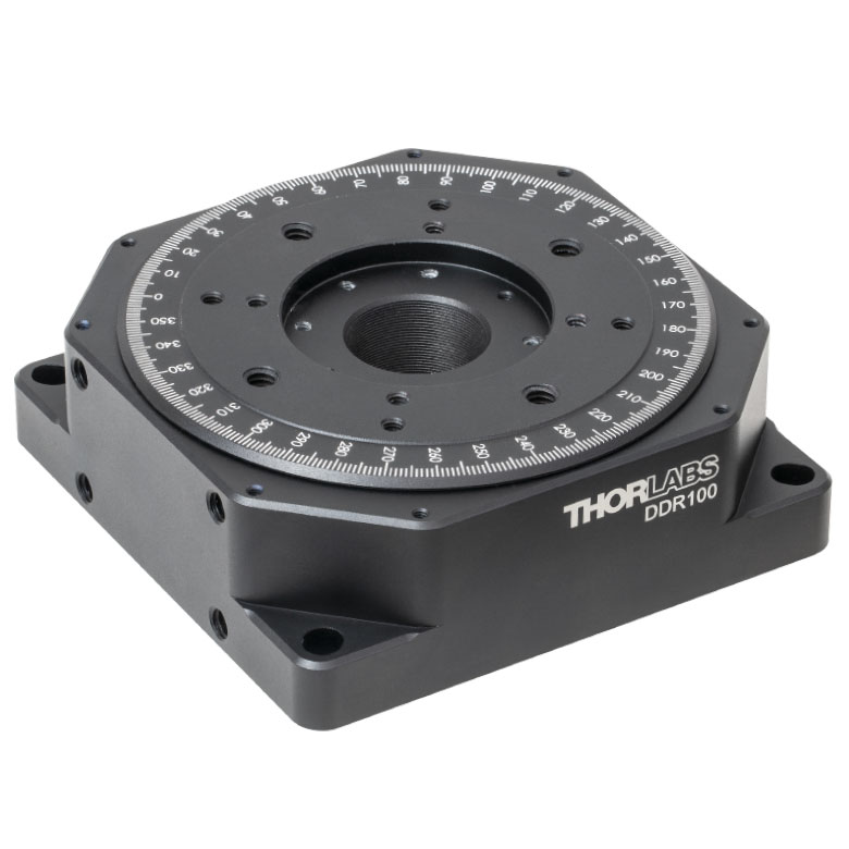 |  | 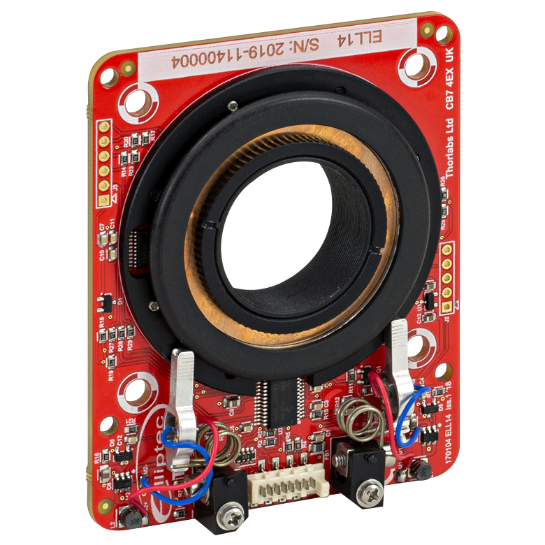 | 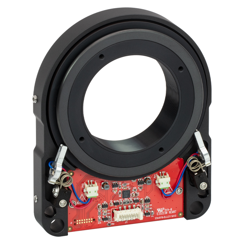 | 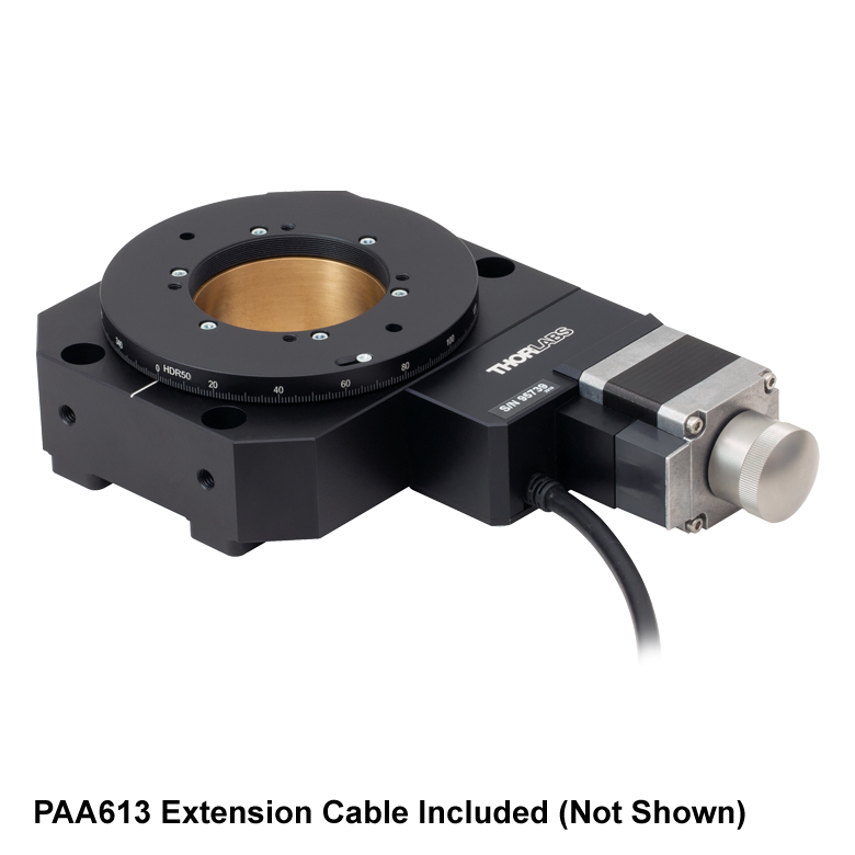 |
| Features | Compatible with SM1 Lens Tubes & 30 mm Cage System | Compatible with SM1 Lens Tubes, 16 mm Cage System, 30 mm Cage System | Compatible with SM05 Lens Tubes, Open Frame Design for OEM Applications | Compatible with SM1 Lens Tubes, Open Frame Design for OEM Applications | Compatible with SM2 Lens Tubes, Open Frame Design for OEM Applications | Compatible with SM2 Lens Tubes | |
| Additional Details | |||||||
| Motorized Rotation Mounts and Stages with Tapped Platforms | ||
|---|---|---|
| Item # | PRMTZ8(/M)a | ELL18(/M)b |
| Click Photo to Enlarge | 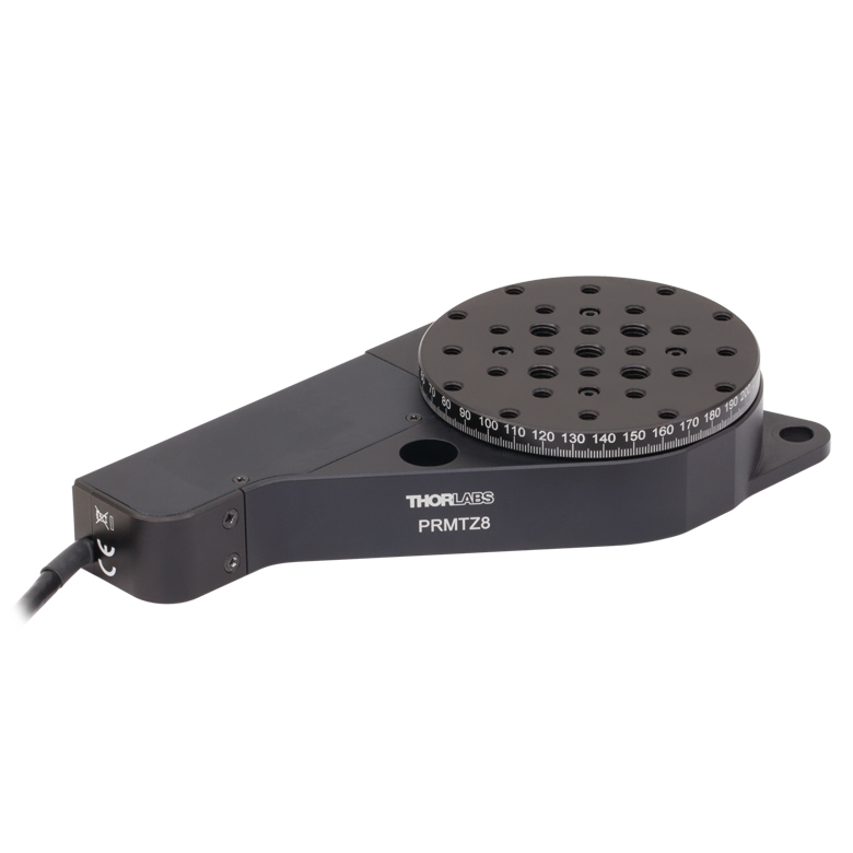 | 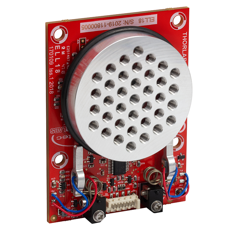 |
| Features | Tapped Mounting Platform for Mounting Prisms or Other Optics | Tapped Mounting Platform, Open Frame Design for OEM Applications |
| Additional Details | ||

 ズーム
ズームVideo 684A 6軸キネマティッの操作方法。この動画ではK6XSを用いてご紹介
していますが、K6X05およびK6X2の操作方法も同様です。
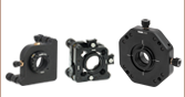
- 6つの調整軸、固定可能(Table 684B参照)
- X、 Y、360°連続回転は独立して調整可能
- Ø12 mm~Ø12.7 mm(Ø1/2インチ)、Ø25 mm~Ø25.4 mm(Ø1インチ)、Ø50 mm~Ø50.8 mm(Ø2インチ)光学素子用マウントをご用意*
- ポスト取付け用のM4 ザグリ穴
6軸キネマティックマウントは、汎用的にご使用いただけるように設計された高精度ポジショナです。光学素子に対して6軸(移動軸と回転軸)の調整をすることができ、各軸には安定性を高めるために固定ネジが付いています。どのマウントにも、ピッチ、ヨー、Z軸調整用に1/4"-80アジャスターネジ、XY軸調整用に3/16"-100アジャスターネジが用いられています。回転する光学素子用セルには目盛が刻印されています。仕様の詳細についてはTable 684Bをご覧ください。

マウントK6XSの回転ダイヤル部には、プリズム取付け用アタッチメントK6A1/M(別売り、下記参照)を取り付けるための#4-40タップ穴が4つ付いています。K6XSのドリフトは、標準的な環境条件(2 °Cの温度変動)で試験したところ、48時間で15 µrad未満でした。K6XSのX軸とY軸のクロストークは全移動範囲において±50 µm未満、K6X05およびK6X2のX軸とY軸では±35 µm未満です。
ピッチ、ヨー、またはZ移動においてさらに高い調整分解能が必要な場合には、3つの1/4"-80アジャスタを差動アジャスタDAS110に交換することができます。
| Table 684B Specifications | |||||||||
|---|---|---|---|---|---|---|---|---|---|
| Item # | Optic Cell Threading | Optic Size | Max Optic Thickness | Pitch/Yaw Adjust (Resolution) | X/Y Adjust (Resolution) | Z Adjusta (Resolution) | Rotation Scale Graduations | Included Retaining Ring | Mounting Counterbores |
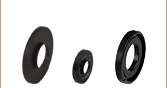
| K6X05 | SM05 (0.535"-40) | Ø1/2" | 0.57" (14.4 mm) | ±4° (6.3 mrad/rev) | ±1.5 mm (254 µm/rev) | ±3.2 mm (318 µm/rev) | Every 2° | SM05RRb | Two #8 (M4) |
| K6XS | SM1 (1.035"-40) | Ø1" | 0.57" (14.6 mm) | ±4° (5 mrad/rev) | ±2 mm (254 µm/rev) | Every 1° | SM1RRc | Six #8 (M4) | |
| K6X2 | SM2 (2.035"-40) | Ø2" | 0.53" (13.4 mm) | ±2° (3.6 mrad/rev) | SM2RRd | ||||
*これらのマウントは、Ø12.7 mm、Ø25.4 mm、Ø50.8 mmの光学素子に対して最適設計されています。それらよりも少々小さな光学素子(Ø12 mm、Ø25 mm、Ø50 mm)に対してもご使用いただけますが、光学素子の偏心が重要ではない用途でのご使用をお勧めします。

 ズーム
ズーム
Click to Enlarge
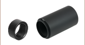
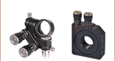
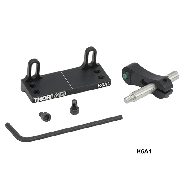
- K6XSの移動セル前面に取付け可能
- プラットフォーム:12.7 mm x 42.7 mm
- 調整範囲:6 mm
プラットフォーム用アクセサリK6A1/Mは、付属の#4-40ネジや六角レンチを使用して6軸キネマティックマウントK6XSの回転リングや、当社の30 mmケージシステム対応回転マウントに取付けられるように設計されています。このプラットフォームは、取り付けた光学素子を回転軸上に配置できるように、6.3 mmの範囲で高さ調整が可能です。プラットフォームの四隅にあるM4 x 0.7タップ穴は、付属のプリズム用クランプアームPM3/Mや、その他のオプトメカニクス部品を取付けるのにお使いいただけます。

 ズーム
ズーム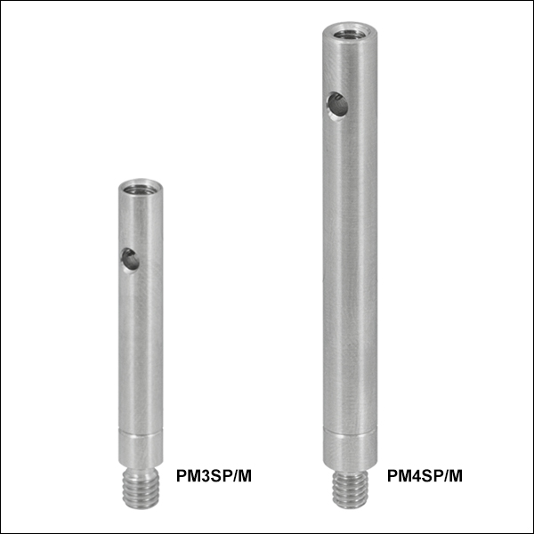
Click to Enlarge
Figure 654B クランプアーム用エクステンションポスト(ミリ規格を示す溝が付いています)
Click for Details
Figure 654A 図面
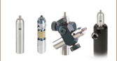
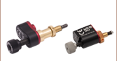
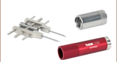
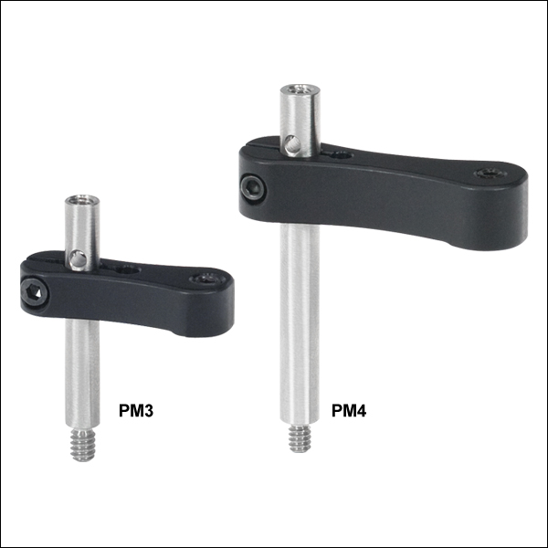
- プラットフォームマウント用のクランプ
- ポストの上部と下部にM4ネジ付き
- PM3/M: 高さ24.6 mmまでの光学素子を保持
- PM4/M: 高さ40.9 mmまでの光学素子を保持
- 保持する光学素子の高さを引き上げるエクステンションポストもごご用意
- PM3SP/M+PM3/M: 高さ56.1 mmまでの光学素子を保持
- PM4SP/M+PM4/M: 高さ91.7 mmまでの光学素子を保持
当社のクランプアームPM3/MならびにPM4/Mは、先端がナイロン製の止めネジ(セットスクリュ)と2.0 mmの六角レンチで、キネマティックプラットフォームマウントやV字型クランプに光学素子を固定します。PM3/Mは高さ24.6 mmまでの光学素子を保持します。ポストと先端がナイロン製の止めネジ間の距離は17.5 mmです。PM4/Mは高さ40.9 mmまでの光学素子を保持し、ポストと先端がナイロン製の止めネジ間の距離は29.3 mmです。クランプアームPM3/MならびにPM4/Mに、それぞれエクステンションポストPM3SP/MまたはPM4SP/Mを使用することにより、保持できる光学素子の高さをさらに引き上げることが可能です。これらのエクステンションポストは、クランプアームの部品のポストと同一です。
すべてのクランプアームはフレクシャ機構でポストに保持されますが、これらは2 mmのボール(六角)ドライバや六角レンチを使って固定されます。ポストにはトルクを加えてポストを締め付けるときに使用する貫通穴も付いています。詳細についてはFigure 654Aをご覧ください。