 Products Home
ピエゾ型ファイバー位相シフター
- Shift the Phase of Light Up to 6.5λ (13π radians) or 27.5λ (55π radians)
- Wavelength Ranges from 1260 to 1625 nm
- Models with Ultra-Low Insertion Loss (<0.05 dB Without Connectors)
- SM and PM Fiber Options
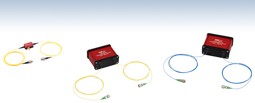
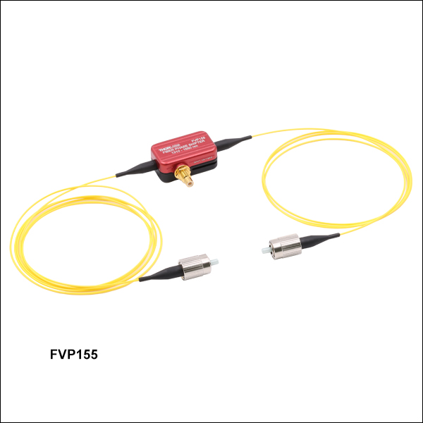
FVP155
1310 - 1550 nm
SM, FC/PC
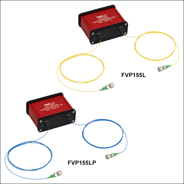
FVP155L
1260 - 1625 nm
SM, FC/APC
FVP155LP
1440 - 1625 nm
PM, FC/APC


Please Wait
特長
Click to Enlarge
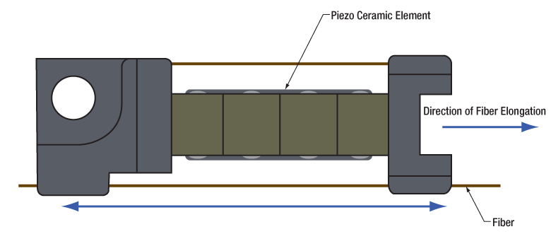
Figure 1.1 ピエゾ型ファイバ位相シフタ
- 最大位相シフト:6.5λ (13π ラジアン)
- 最大入力駆動周波数:20 kHz
- 波長範囲:1310~1550 nm
- 閉ループまたは開ループ動作で使用
こちらのピエゾ素子を使用したファイバ位相シフタFVP155は、デバイスを通過するシングルモードファイバを伸長させることで、1310~1550 nmの光の位相を変化させます。圧電セラミック素子の両端にファイバが固定されており、素子の圧電効果によってファイバを伸長させます(Figure 1.1の概略図参照)。位相シフタFVP155は、150 Vで約6.5λ(13π)の位相ストロークを発生させることができ、少なくともλ(2π)の位相ストロークを維持しながら、20 kHzの高い入力周波数で動作します。 位相ストローク対入力電圧(Figure 3.1)および位相ストローク対周波数(Figure 3.2)の典型的なグラフは「グラフ」タブでご覧いただけます。なお、デバイスには2.0 mmのナローキーFC/PCコネクタが付いており、必要に応じてクランプCL6を用いて光学テーブルに固定可能です。

Click to Enlarge
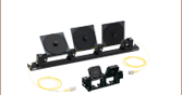
Figure 1.2 ピエゾ型ファイバ位相シフタFVP155を干渉計に組み込み、ピエゾコントローラK-Cube®KPC101を使用して光路長を安定化させることができます。FOC = 光ファイバーカプラ、PC = 偏光コントローラ、PD = フォトディテクタ
位相シフタFVP155は、SMC入力を介して当社の多数のピエゾコントローラで制御可能です。対応可能なデバイスと帯域幅の一覧は、「コントローラのセレクションガイド」タブ内のTable 4.1に掲載しています。位相シフタFVP155には、高温下でのデバイスの損傷を防ぐためのサーマルスイッチも内蔵されています。デバイスが過熱すると回路が切断され、温度が約50 °Cまで下がると自動的に再接続されます。高い周波数で変調するとデバイスの温度上昇が速くなります。過熱を防ぐための周波数ごとの推奨最大電圧を、「仕様」タブTable 2.2に示していますのでご参照ください。
ファイバ位相シフタは上記のように数多くの用途にご使用いただける汎用性の高いデバイスです。入力された光信号の位相を正確に制御・変調することで、高精度な測定、センシングおよびレーザ技術応用研究が可能です。Figure 1.2に、デバイスをファイバ干渉計に組み込んで光路長を安定化させるための概略図を示しています。
| Table 2.1 FVP155 Phase Shifter Specificationsa | |
|---|---|
| Drive Voltage Range | 0 - 150 V |
| Phase Stroke at 150 V and 1 kHzb | 13π radians ± 15% |
| Half-Wave Voltage | < 11 V |
| Capacitancec | 200 nF ± 15% |
| Resonant Frequency | 80 kHz ± 15% |
| Insertion Loss | < 0.1 dB (Without Connectors) |
| Residual Amplitude Modulation | < 0.15% |
| Operating Wavelength | 1310 - 1550 nm |
| Operating Temperature | 0 - 50 °C |
| Electrical Connector | SMC Male |
| Fiber Type | SM1550P |
| Fiber Connectors | FC/PC Narrow Key (2.0 mm) |
| Storage Temperature | -40 - 85 °C |
| Dimensionsd (L x W x H) | With Fiber: 2000.0 mm × 28.2 mm × 12.0 mm (78.74" x 1.11" x 0.47") Housing With Connector: 29.0 mm × 28.2 mm × 12.0 mm (1.14" x 1.11" x 0.47") Housing Only: 29.0 mm × 17.0 mm × 12.0 mm (1.14" x 0.67" x 0.47") |
| Table 2.2 FVP155 Phase Shifter Recommended Voltage Limitsa | ||
|---|---|---|
| Frequency | Voltage Limit | Phase Shift |
| 2.0 kHz | 150 V | 14π radians |
| 2.5 kHz | 105 V | 11π radians |
| 3.5 kHz | 90 V | 10π radians |
| 5.0 kHz | 75 V | 9π radians |
| 8.0 kHz | 60 V | 8π radians |
| 11.0 kHz | 55 V | 7π radians |
| 15.0 kHz | 50 V | 6π radians |
| 20.0 kHz | 45 V | 4π radians |
性能グラフ
すべての位相シフタFVP155の性能グラフは、特に記載のない限り25 °Cでの典型値です。
Click to Enlarge
Click for Raw Data
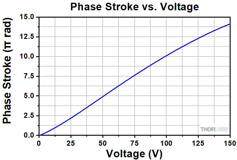
Figure 3.1 位相シフタFVP155の位相ストロークと入力電圧の関係を示したグラフ(典型値)。2 kHzの入力変調周波数で測定しています。
Click to Enlarge
Click for Raw Data
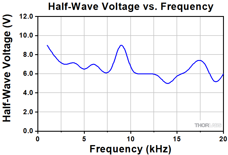
Figure 3.3 1550 nmにおける位相シフタFVP155の半波電圧と周波数の関係を示したサンプルデータ。 データは代表値であり、デバイス毎に異なる場合があります。
Click to Enlarge
Click for Raw Data
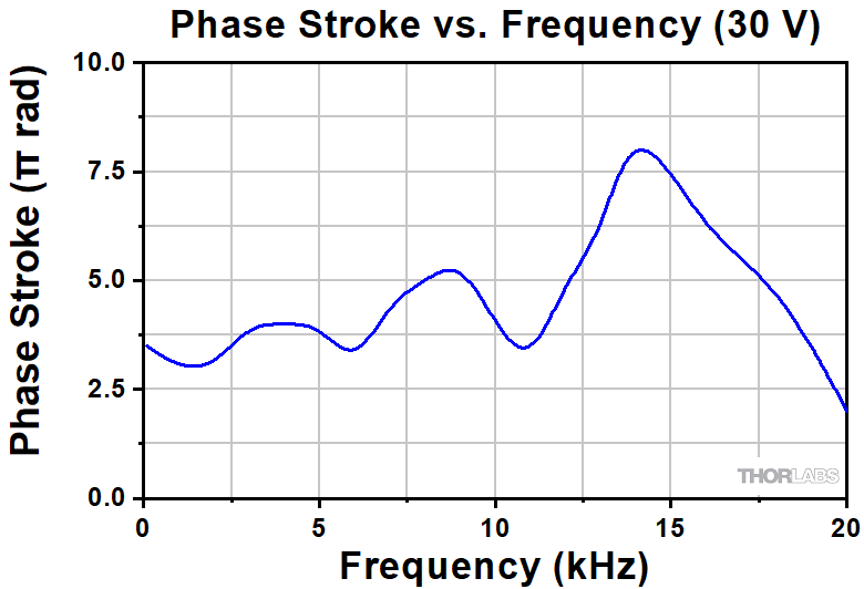
Figure 3.2 1550 nmにおける位相シフタFVP155の位相ストロークと周波数の関係を示したサンプルデータ。データは代表値であり、デバイス毎に異なる場合があります。
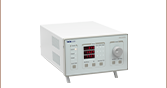
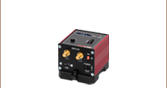
| Table 4.1 FVP155 Phase Shifter Controller Selection Guide | ||||||
|---|---|---|---|---|---|---|
| Item # | Channels | Bandwidth | Voltage Range | Maximum Current | Suggested Bandwidtha | Recommended Cable |
| BPC301 | 1 | 10 kHz (1 µF Load, 1 Vpp) | 0 - 150 V | 0.5 A | 3 kHz(150 Vpp) 26 kHz(30 Vpp) | PAA100 or PAA101 |
| BPC303 | 3 | 1 A | 3 kHz(150 Vpp) 30 kHz(30 Vpp) | |||
| MPZ601 | 2 | 10 kHz (1 µF Load, 1 Vpp) | 0 - 75 V DC (Software) | 0.5 A | 10 kHz(75 Vpp) 26 kHz(30 Vpp) | |
| 0 - 90 V DC (External Input) | 8 kHz(90 Vpp) 26 kHz(30 Vpp) | |||||
| KPC101 | 1 | 1 kHz (1 µF Load, 1 Vpp) | 0 - 150 V | 0.012 A | 0.09 kHz(150 Vpp) 0.6 kHz(30 Vpp) | |
| MDT694B | 1 | 9 kHz (No Load, Small Signal) 8.5 kHz (No Load, 150 Vpp) 200 Hz (1.4 µF Piezo, 150 Vpp)b | 0 - 150 V | 0.06 A | 0.6 kHz(150 Vpp) 3 kHz(30 Vpp) | CA26XX Series |
| MDT693B | 3 | |||||
| BPA100 | 1 | See the Responsivity Curves on the Overview tab of the BPA100 Amplifier webpage | 0 - 150 V | 2.5 A | 20 kHz(150 Vpp) 30 kHz(30 Vpp) | CA26XX and T4004 |
 (1)
(1)
| Posted Comments: | |
Ely Eastman
(posted 2025-08-21 16:59:31.75) Hello,
I am curious how long the fiber enclosed in the device is.
Best,
Ely jdelia
(posted 2025-08-22 08:00:31.0) Thank you for contacting Thorlabs. The fiber is fixed at both ends of the piezoelectric ceramic in a stretched state, with a total length of 2000 mm. The length of the fiber enclosed in the device is equal to the housing (~29 mm). |

 ズーム
ズーム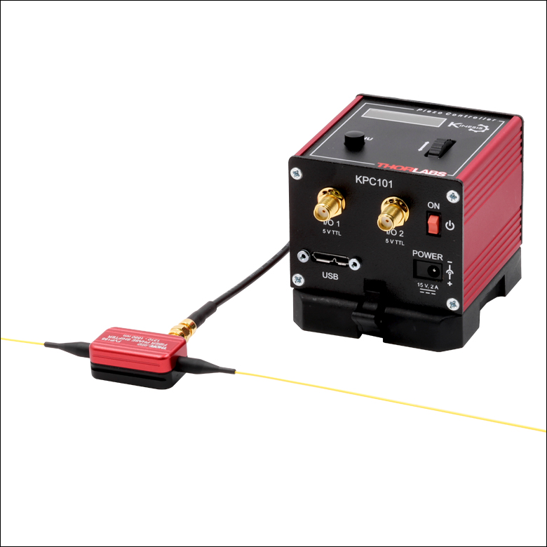
- Phase Shifts Up to 6.5λ (13π Radians)
- Input Wavelength Range:1310 to 1550 nm
- FC/PC Narrow Key Connectors
The FVP155 phase shifter can produce a phase stroke of about 6.5λ (13π) at 150 V and operates with input frequencies as high as 20 kHz while maintaining a phase stroke of at least λ (2π). Note that the connectors on the device are narrow key FC/PC (2.0 mm) and that the device can be clamped to an optical table using a CL6 clamp, if needed.
The FVP155 phase shifter is also equipped with a thermal switch to prevent damage to the device under high temperatures. When the device overheats, the circuit will be broken, and it will automatically reconnect when the temperature drops to around 50 °C. Since the device heats up faster when modulated at higher frequencies, we provide a list of recommended maximum voltages as a function of frequency to prevent overheating in Table 2.2 in the Specs tab, for reference.

 ズーム
ズーム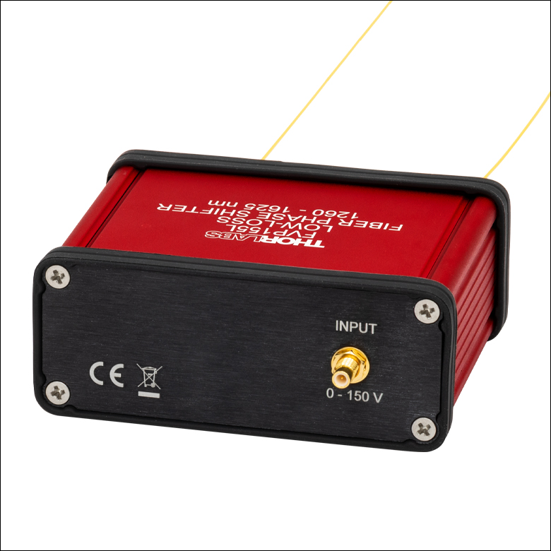
Click to Enlarge
Figure G2.1 The FVP155L and FVP155LP include an SMC connector for an external controller.
- Phase Shifts Up to 27.5λ (55π Radians)
- Input Wavelength Ranges:
- FVP155L: 1260 to 1625 nm, SM
- FVP155LP: 1440 to 1625 nm, PM
- Ultra-Low Insertion Loss of <0.05 dB (Without Connectors)
- Compact Housing
- FC/APC Narrow Key Connectors
The FVP155L and FPV155LP low-loss phase shifters can produce a phase stroke of about 27.5λ (55π) at 150 V and operates with input frequencies as high as 20 kHz. The high phase shift allows for fine and coarse tuning, and the narrow resonant frequency enables the user to drive the device up to 20 kHz with stable temperatures. These are fiber-coil-based devices that, by maintaining a large fiber bend radius, can offer very low insertion losses of <0.05 dB and are well-suited for quantum computing applications such as fiber link stabilization.
The FVP155L uses SMF-28 Ultra fiber with an operating range of 1260 nm to 1625 nm and offers a low polarization dependent loss (<0.01 dB), suitable for applications where input light polarization can vary. The FVP155LP uses PM1550-XP fiber with an operating range of 1440 nm to 1625 nm and offers >18 dB polarization extinction ratio for applications that require maintaining a linear light polarization throughout the fiber setup.