Products Home
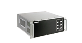
ベンチトップ型自動アライメントコントローラNanoTrak®
- Advanced Active Alignment
- High-Voltage Piezo Output Channels for Precise Positioning
- IR (InGaAs) Detector Included
- Visible (Si) Detector Available Separately
Supplied with a Full Suite of Software Support Tools
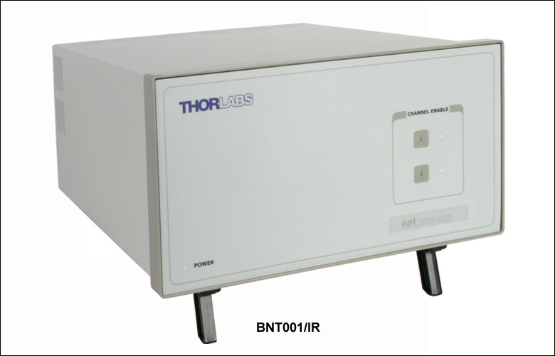
BNT001/IR
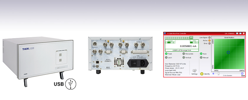
Front Panel
Back Panel
(See Front & Back Panel Tab)


Please Wait
用途例
- ファイバ同士のアクティブアライメント
- ファイバ光学系と自由空間光学系のアクティブアライメント
- 光学デバイスのアライメント
- 導波路の接続
- ファイバの特性評価および試験
- アクティブ・パッシブデバイスのファイバ取り付け
- 光学系全体の高スループット維持
| Benchtop Motion Controllers |
|---|
| 1- and 2-Channel Brushless DC Servo Controllers |
| 1-, 2-, and 3-Channel Stepper Motor Controllers |
| 1- and 3-Channel Open Loop Piezo Controllers |
| 1- and 3-Channel Closed Loop Piezo Controllers |
| 2-Channel NanoTrak® Auto-Alignment Controller |
特長
- 高度な光検出アルゴリズムを用いたアクティブアライメントシステム
- トラッキング機能による適切な光透過効率の恒久的な維持
- アライメントの安定性を長期にわたって維持するためのLatchモード
- 2つのピエゾコントローラ出力閉ループフィードバック
- 赤外域(IR)用InGaAsディテクタおよびSMBコネクタが付属
- 可視域(VIS)用Siディテクタヘッドを別売りにてご用意
- サードパーティのカスタム用途向けソフトウェアGUI制御セットおよびサポート
- 2軸コントローラを2台接続により、最大4軸にアップグレード可能
自動アライメントコントローラNanoTrak®は、アクティブフィードバックのアライメント制御システムと、2チャンネル型のピエゾコントローラを組み合わせて1つのベンチトップ型ユニットに組み込んでいます。このシステムは、高度なアライメントシステムを素早く構成するためのベースとなるシステムです。当社の3軸NanoMaxや6軸NanoMaxのピエゾアクチュエータ付きフレクシャーステージを含め当社が幅広くご用意していピエゾを用いた位置決めシステムに組み込み可能です。
2つのデバイス(例:ファイバ)からの光を結合するために、最初に信号が検出されるまで、デバイスを移動しての検索します。NanoTrakのサポートソフトウェア は、この最初の光検出用に一連の検索アルゴリズムを提供します。NanoTrakは主に光ファイバや光集積装置のアライメントに使われていますが、導波路の特性解析、アクティブおよびパッシブデバイスのファイバーピグテール付け、その他多くのR&D用途のような手間のかかるアライメント作業の自動化にも適しています。
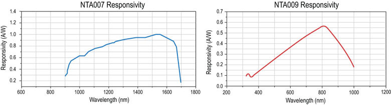
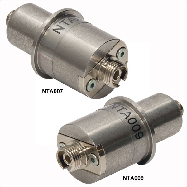
NanoTrakには、赤外(IR)域波長用InGaAsディテクタ(型番NTA007)と外部ディテクターヘッドとご使用いただくPINダイオードSMB入力が付属しています。可視(VIS)域波長用のSiディテクタ(型番NTA009)は別途ご購入いただけます(Table 1.1からご覧ください)。SMBメス-BNCオスの長さ914 mmのケーブルPAA236Rも別売りでご用意しております。
| Table 1.1 NanoTrak® Automated Fiber Alignment Controllers | ||
|---|---|---|
| K-Cube® 2-Channel Controllers | Benchtop 2-Channel Controller | Modular 2-Channel Rack System Module |
BNT001/IRの仕様
| Signal Measurement | |
|---|---|
| PIN Photo-Diode Input | |
| Connector Type | SMB male |
| Current Range | 1 nA to 10 mA Photocurrent |
| Visible Light Detector | |
| Connector Type | FC/PC |
| Detector Type | Silicon (Si) |
| Operating Wavelength | 320 - 1000 nm |
| IR Detector | |
| Connector Type | FC/PC |
| Detector Type | InGaAs |
| Operating Wavelength | 900 - 1700 nm |
| NanoTraking | |
| Circle Scanning Frequency | 1 to 300 Hz |
| Circle Position Range | < 1% to >99% Maximum Piezo Extension (MPE) |
| Circle Diameter Adjustment Modes | Automatic and Manual |
| Signal Phase Compensation | -180° to 180° |
| Piezoelectric Input/Output | |
| Number of Piezo Channels | 2 |
| HV Output Connectors | |
| Connector Type | SMC male |
| Voltage Output | 0 to 75 VDC/Channel |
| Voltage Stability | 100 ppm over 24 Hours |
| Noise | < 3 mV (rms) |
| Output Current | 500 mA/Channel |
| Analog Output Monitors | |
| Connector Type | BNC |
| Voltage Range | 0 to 10 VDC |
| Analog Drive Inputs | |
| Connector Type | BNC |
| Voltage Range | 0 to 10 VDC |
| Strain Gauge Position Feedback | |
| Connector Type | 9 Pin D-type Female |
| Feedback Type | AC |
| Other Input/Output | |
|---|---|
| Optical Power Monitor | |
| Connector Type | BNC |
| Voltage Range | 0 to 10 VDC |
| User Control | |
| Connector Type | 37 Pin D-Type Female |
| Isolated Digital Inputs | 8 off TTL |
| Isolated Digital Outputs | 4 off TTL |
| Trigger Input | 1 off TTL |
| Trigger Output | 1 off TTL |
| Potentiometer Channel Control Input | 1 kΩ to 10 kΩ (each channel) |
| Analog Channel Output Monitors | 0 to 10 VDC (each channel) |
| LV Channel1 Output / Trigger Output | |
| Connector Type | BNC |
| Voltage Range (LV Ch1 Mode) | 0 to 10 VDC |
| Trigger Output Mode | TTL |
| LV Channel 2 Output / Trigger Input | |
| Connector Type | BNC |
| Voltage Range (LV Ch2 Mode) | 0 to 10 VDC |
| Trigger Input Mode | TTL |
| USB Port | |
| Connector Type | Type B |
| Speed | USB1.1 |
| Power Requirementsa | |
| Voltage | 85 to 264 VAC |
| Frequency | 47 to 63 Hz |
| Power | 200 W |
| Fuse | 3A |
| General | |
| Dimensions (W x D x H) | 245 x 130 x 330 mm |
| Weight | 6 kg (13 lbs) |
NTA009の仕様
| Spectral Range | Active Area | Fiber Input | Rise Time | NEP | Dark Current |
|---|---|---|---|---|---|
| 320 - 1000 nm | Ø 0.8 mm | FC/PC Bulkhead | 100 ps @ 12 V | 3.1 x 10⁻¹⁵ W/√Hz | 0.01 nA @ 10 V |
NTA007の仕様
| Spectral Range | Active Area | Fiber Input | Rise Time | NEP | Dark Current |
|---|---|---|---|---|---|
| 900 - 1700 nm | Ø 0.12 mm | FC/PC Bulkhead | 300 ps @ 5 V | 4.5 x 10⁻¹⁵ W/√Hz | 0.05 nA @ 5 V |
ユーザI/Oコントローラ
Dタイプメス型
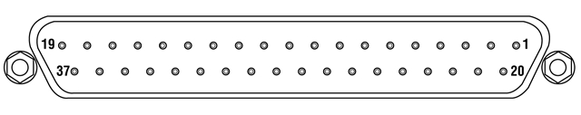
| Pin | Description | Return | Pin | Description | Return | Pin | Description | Return |
|---|---|---|---|---|---|---|---|---|
| 1 | Ch 1 RS485 (-) | 20 | 14 | DIG I/P 3a | 27 to 37 | 27 | Isolated Groundb | - |
| 2 | Ch 2 RS485 (-) | 21 | 15 | DIG I/P 4a | 27 to 37 | 28 | Isolated Groundb | - |
| 3 | Not Used | - | 16 | DIG I/P 5a | 27 to 37 | 29 | Isolated Groundb | - |
| 4 | Potentiometer Wiper Ch 1 | - | 17 | DIG I/P 6a | 27 to 37 | 30 | Isolated Groundb | - |
| 5 | Potentiometer Wiper Ch 2 | - | 18 | DIG I/P 7a | 27 to 37 | 31 | Isolated Groundb | - |
| 6 | Channel 1 10 V O/Pd | - | 19 | DIG I/P 8a | 27 to 37 | 32 | Isolated Groundb | - |
| 7 | Channel 2 10 V O/Pd | - | 20 | Ch 1 RS485 (+) | 1 | 33 | Isolated Groundb | - |
| 8 | DIG O/P 1a | 27 to 37 | 21 | Ch 2 RS485 (-) | 2 | 34 | Isolated Groundb | - |
| 9 | DIG O/P 2a | 27 to 37 | 22 | Potentiometer Reference | 23 | 35 | Isolated Groundb | - |
| 10 | DIG O/P 3a | 27 to 37 | 23 | Analog Ground | - | 36 | Isolated Groundb | - |
| 11 | DIG O/P 4a | 27 to 37 | 24 | External Trigger O/Pc | - | 37 | Isolated Groundb | - |
| 12 | DIG I/P 1a | 27 to 37 | 25 | External Trigger I/Pc | - | |||
| 13 | DIG I/P 2a | 27 to 37 | 26 | 5 V User O/P (Isolated) | 27 to 37 |
ピエゾコントローラ
Dタイプメス型
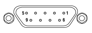
| Pin | Description | Return | Pin | Description | Return | Pin | Description | Return |
|---|---|---|---|---|---|---|---|---|
| 1 | Wheatstone Bridge Excitation | 4 or 6 | 4 | d.c.(+) or Equipment Groundc | - | 7 | d.c.(-) or Actuator ID Signalb,c | 4 or 6 |
| 2 | +15Va | 4 or 6 | 5 | Feedback Signal In | 4 or 6 | 8 | RS485 (-) | 9 |
| 3 | -15Va | 4 or 6 | 6 | Equiptment Ground | - | 9 | RS485 (+) | 8 |
信号In
BNCメス型
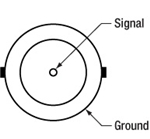
0~10 Vで、抵抗値は100 kΩ。 外部のパワーメータから光パワー信号を受信するために使用します。
信号Out
BNCメス型
0~10V、2mA。 OPTICAL IN端子で受けたパワー信号をモニタするためにオシロスコープに接続できます。
HV OUT
SMC

0~75 V、0~250 mA。駆動信号をピエゾアクチュエータに送ります。
Ext In (+)とExt IN (-)
BNCメス型
外部からピエゾアクチュエータの位置を制御するときに利用します。 0~±10Vで、抵抗値は100kΩ。 極性は、設定パネル内、またはPiezo SetIPSourceメソッドを呼び出してソフトウェア上で選択します。 2つの信号の差分は、HV OUTコネクタに送られる前に、内部で増幅されます。
LV Ch1/Trig. Out
とLV Ch2/Trig. In
BNCメス型
0~+10V。ここからの出力は、HV OUTに反映され、10VがHV出力端子の75Vと等しくなります。また、オシロスコープに接続できるので、ピエゾアクチュエータの駆動信号がモニタできます。
PC接続用
USB Aタイプ
USBケーブル付属
前面パネル
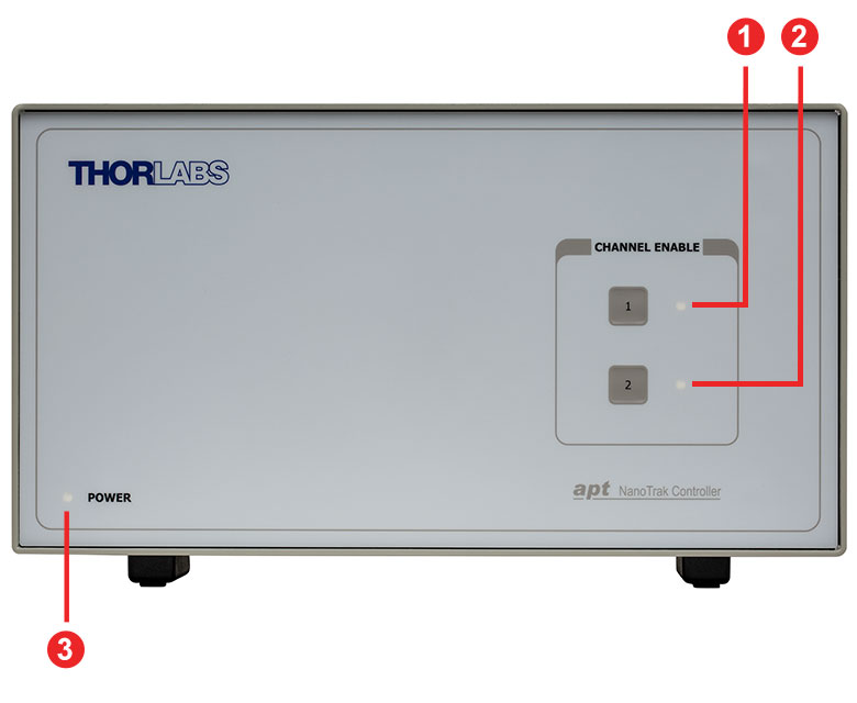
| Callout | Description |
|---|---|
| 1 | Enable/Disable Channel 1 Button |
| 2 | Enable/Disable Channel 2 Button |
| 3 | Power LED |
背面パネル
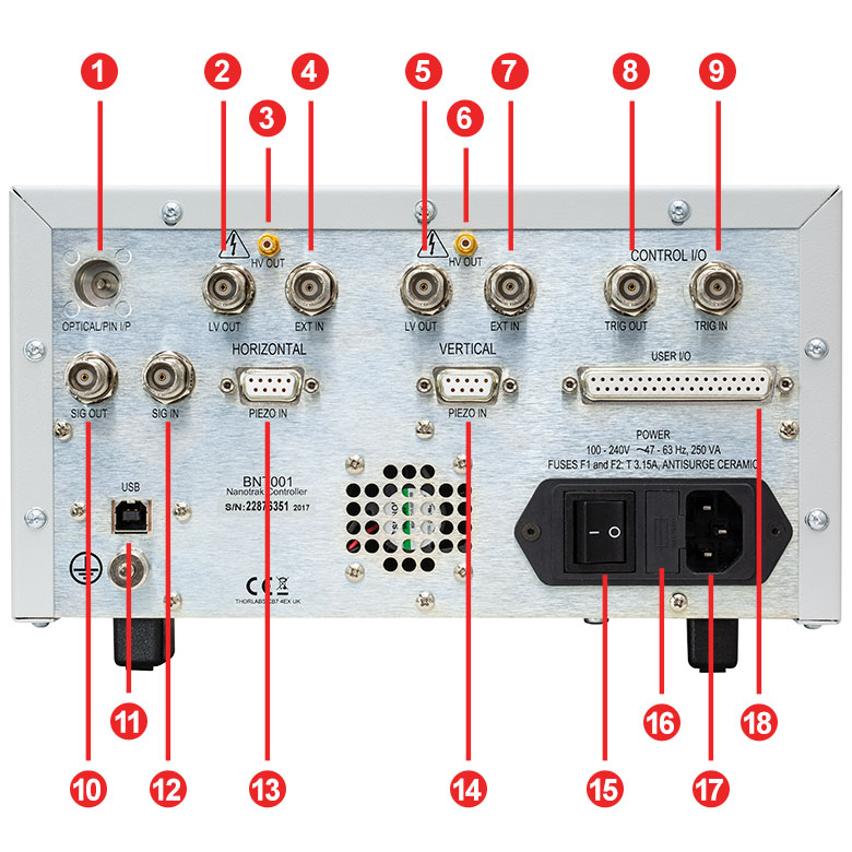
| Callout | Description |
|---|---|
| 1 | 3.5 mm Jack for Optical/Pin I/Pa |
| 2 | BNC for Monitor Out for Horizontal Actuator |
| 3 | SMC Connector HV Out for Horizontal Actuator Drive Signal |
| 4 | BNC for Monitor In for Horizontal Actuator |
| 5 | BNC for Monitor Out for Vertical Actuator |
| 6 | SMC Connector HV Out for Vertical Actuator Drive Signal |
| 7 | BNC for Monitor In for Vertical Actuator |
| 8 | BNC for Control I/O Trigger Out |
| 9 | BNC for Control I/O Trigger In |
| 10 | BNC Signal Out for an External Power Meeter |
| 11 | USB Type-B Port for System Communications |
| 12 | BNC Signal In for an External Power Meter |
| 13 | 9-Pin D-Type Female Port Input for Horizontal Movement |
| 14 | 9-Pin D-Type Female Port Input for Vertical Movement |
| 15 | Main Power Switch |
| 16 | Fuse Holder |
| 17 | AC Power Cord Connector |
| 18 | 37-Pin D-Type Female Port for Programmable I/O |
動作原理
NanoTrak®では、北極を探すコンパスに似た操作を行なう勾配探索アルゴリズムを使って自動アライメントを行ない、ピーク信号の方向を特定します。検索は感度が高く、小さな(ピーク信号から遠く離れた)パワー勾配でさえも、NanoTrakはピーク信号がどの方向にあるか判断することがで きます。この情報を使って、装着された高速ピエゾアクチュエータで位置の補正を行なうので、広い範囲をマッピングまたは検索する必要がありません。
ピーク信号の近くでは信号の勾配はずっと小さく見えるので、より小さな位置補正が必要となります。ピーク信号に届くと、見える勾配はゼロになり、位置補正は必要ないということを示します。
NanoTrakの動的な操作により、アライメント作業を無限に続けることが可能です。アライメントが変わると、勾配検索は変化を検出して補正作業を行ないます。
一般的な使用例 (光学デバイスのアライメント)
アライメント下でのシステムへの光パワーの透過は、ガウス型結合として説明できます。結合パワーはアライメントされた(デバイスによる)位置からの相対距離に応じて低くなります。それぞれのパワーレベルでのアライメント位置は、距離が等しいと考えられます。 これらの離散的なパワーアライメント位置は同心円を形成します。これらの同心円はパワーの輪郭(外形)を表し、地図上の丘の等高線として考えられます。
一定の位置でのパワー勾配を検出することによって、NanoTrakはパワーが最大になるまでその位置を調整して勾配をゼロにすることができます。 これは円形の路にある輪郭をスキャンして円形軌道上で最大の信号方向を確立することによって行なわれます。スキャンした円の始点は最大信号の方向に移動さ れます。
連続した動的アライメントを使ってアライメントを維持することができます。また、次の段階のアセンブリやR&D操作のために検索アルゴリズムを中止することもできます。
ソフトウェア
Kinesisバージョン1.14.52
このKinesisソフトウェアパッケージには、当社のKinesisシステムコントローラを制御するためのGUIが含まれています。
下記もご用意しております。
- 通信プロトコル

Figure 58A KinesisソフトウェアのGUI画面
当社のKinesis®ソフトウェアパッケージを用いて、当社の様々なモーションコントローラを駆動することができます。このソフトウェアは小型で低出力のシングルチャンネルドライバ(K-Cube®など)から、高出力でマルチチャンネルのベンチトップ型ユニットやモジュール型の19インチラックナノポジショニングシステム(ラックシステムMMR60x)まで、当社Kinesisシリーズの様々なモーションコントローラの制御用にご使用いただけます。
Kinesisソフトウェアでは.NETコントロールを使用できるため、最新のC#、Visual Basic、LabVIEW™、あるいはその他の.NET対応言語を使用してカスタムプログラムを作成することができます。.NETフレームワークの使用を想定していないアプリケーションのために、ローレベルのDLLライブラリも含まれています。中央シーケンスマネージャ(Central Sequence Manager)は、当社のすべてのモーションコントロール用ハードウェアの統合と同期の機能をサポートしています。
この共通のソフトウェアプラットフォームにより、ユーザは単一のソフトウェアツールを習得するだけで、あらゆるモーションコントロールデバイスを1つのアプリケーション内で組み合わせて使用することができます。このように1軸システム用から多軸システム用までのあらゆるコントローラを組み合わせ、それら全てを1台のPCの統合されたソフトウェアインターフェイスから制御できます。
このソフトウェアパッケージには2つの使い方があります。1つはGUI(グラフィカルユーザーインターフェイス)ユーティリティを用いる方法で、コントローラの到着後すぐに直接的な操作と制御を行なうことができます。もう1つは一連のプログラミングインターフェイスを用いる方法で、ご希望の開発言語によりカスタム仕様の位置決めやアライメント用のプログラムを簡単に作成することができます。
Kinesisソフトウェアでは新しい.NETコントロールが使用でき、最新の最新のC#, Visual Basic, LabVIEW™、ほかの.NET対応言語を使用する開発者がカスタムにプログラムを作成することもできます。
C#
このプログラミング言語はマルチプログラミングパラダイムやマルチプログラミング言語が使用可能となるよう設計されているため、複雑な問題が簡単かつ効率的に解決できます。型付け、命令型、宣言型、関数型、ジェネリック、オブジェクト指向、そしてコンポーネント指向が含まれます。 この共通のソフトウェアプラットフォームにより、1セットのソフトウェアツールを習得するだけで、あらゆるKinesisコントローラを簡単に組み合わせることができます。このようにして1軸システムのコントローラから多軸システムのコントローラまで、様々なコントローラを組み合わせ、全てを1台のPCのソフトウェアインターフェイスから制御することが可能となりました。
Kinesisシステムソフトウェアを使用するには2つの手段があります。コントローラを直接つないで制御を行なう付属のGUI(グラフィカルユーザーインターフェイス)ユーティリティ、またはご希望の開発言語でカスタム仕様の位置決めやアライメントを簡単にプログラムできる一連のプログラミングインターフェイスです。
Kinesisモーションコントロールライブラリの構築の参考となる実行可能なプロジェクト機能拡張例については下のリンクをクリックしてください。なお、Quick Startのプロジェクト例の実行には別の統合開発環境(IDE)(Microsoft Visual Studioなど)が必要です。C#のプロジェクト例はKinesisソフトウェアパッケージに付属する.NETコントロールで実行可能です(詳細は「Kinesisソフトウェア」タブをご覧ください)。
 | Click Here for the Kinesis with C# Quick Start Guide Click Here for C# Example Projects Click Here for Quick Start Device Control Examples | |
LabVIEW
LabVIEWは、.Netコントロールを介してKinesisベースのコントローラとの通信に使用できます。LabVIEWでは、ツールとオブジェクトでフロントパネルとして知られるユーザーインターフェイスを構築した後、グラフィカル表記の関数を使ってコードを追加し、フロントパネルのオブジェクトを制御します。下記のLabVIEWチュートリアルでは.Netコントロールを使用してLabVIEW内Kinesis駆動デバイス用の制御GUIを作成するための情報をご提供しています。 LabVIEWでコントローラを制御する基本的な方法や、LabVIEW GUIを用いてデバイスを操作する前に行うべき設定の手順についても解説しています。
 | Click Here to View the LabVIEW Guide Click Here to View the Kinesis with LabVIEW Overview Page | |
| Posted Comments: | |
Anders Harpøth
(posted 2023-05-10 06:18:27.943) Dear Thorlabs
I have the NanoTrak® Auto-Alignment Controller (BNT001).
I would like the functionality of the NTA009 NanoTrak® Visible Light (Si) Detector Head, 320 - 1000 nm, but I would prefer to avoid the optical patch-cord and have the Si photodiode near the light source and then connect through the standard SMB connector on the controller.
So basically my question is what detector setup do I need to mimic what's inside the NTA009?
Thank you
Best regards
Anders do'neill
(posted 2023-05-15 07:00:16.0) Response From Daniel at Thorlabs. There is functionality with the BNT001 to connect to an external detector using the BNC "Sig In" connector that receives a 0 to 10 V signal. I will reach out to you directly to discuss your application. Vedavyas Sivakumar
(posted 2022-07-14 12:19:35.267) Can I get the wavelength/responsivity data for this detector? cwright
(posted 2022-07-15 08:18:12.0) Response from Charles at Thorlabs: Thank you for contacting us. We have reached out to you with the requested data. empire135
(posted 2016-10-25 12:36:39.393) I lost my software CD. Can i get a software? I have a serial number of BNT001(SN:22829095). bhallewell
(posted 2016-10-25 08:55:19.0) Response from Ben at Thorlabs: Thank you for your product feedback. You can download our new Kinesis software Motion Control software from the following link. Here you can also find further links to resources including example code as well as links to our legacy software package, APT.
https://www.thorlabs.de/software_pages/ViewSoftwarePage.cfm?Code=Motion_Control frederic.vandijk3-5lab.fr
(posted 2015-06-16 08:40:20.147) I finally succeeded in making the system work. It works very well. The software interface is very intuitive and efficient. We are going to save a lot of time during the numerous optical alignments. msoulby
(posted 2015-06-16 03:52:11.0) Response from Mike at Thorlabs: I am glad to hear that you have solved the problem and we appreciate your feedback on the software interface. Please feel free to contact us if you have any further questions. frrederic.vandijk
(posted 2015-06-13 09:40:40.387) We just acquired a BNT001/IR system. I installed the software downloaded from the net successfully (no CD delivered with the system), installed it on a windows7 os pc, re-started the pc after connecting the BNT001/IR and couldn't see the user interface when using the APT-user software. Can you help me with this big problem? msoulby
(posted 2015-06-16 03:45:45.0) Response from Mike at Thorlabs: If the user interface does not appear there are a few things that can typically cause this. 1) Please ensure all USB cables are connected prior to powering up the controller, this is to help ensure USB communication is established correctly. 2) Check that the simulator mode is disabled in APT config, having this enabled accidently will prevent you from using the actual unit. 3) In APT User if the interface is not displayed you can check the View menu and then expand the 'graphical panels' sub-menu, in here you will be able to open or close any active devices that are currently connected. Laurie
(posted 2009-02-05 17:12:29.0) Response from Laurie at Thorlabs to melsscal: Thank you for your interest in our BNT001 nano trak controller. Yes, it can be used with our MAX313/M. melsscal
(posted 2009-02-05 03:45:50.0) Can we use BNT001 as Nano Track Controller with MAX313/M ? Regards A.K.Bose |

 ズーム
ズーム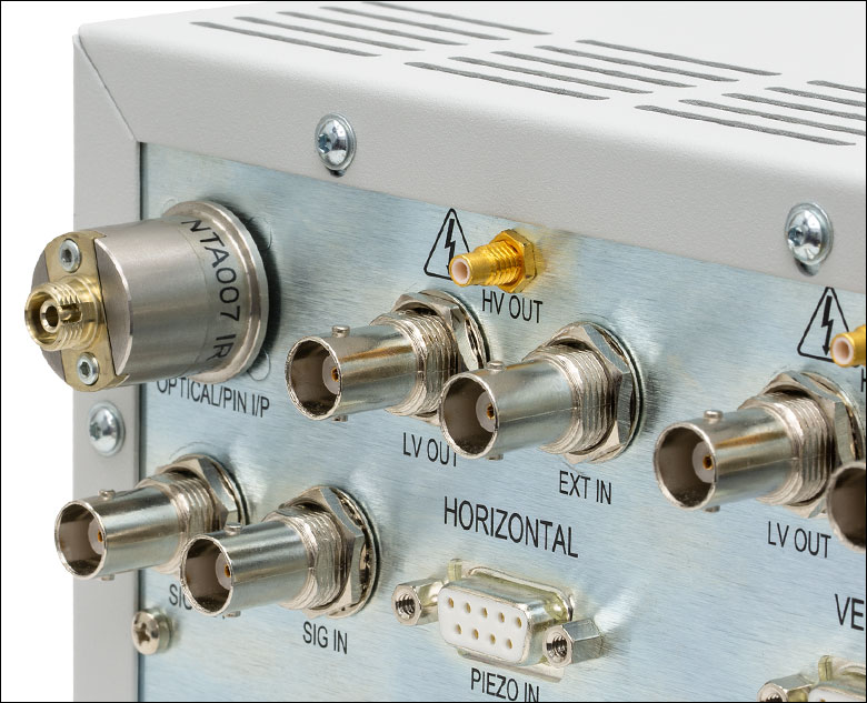
Click to Enlarge
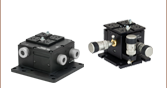
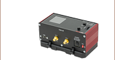
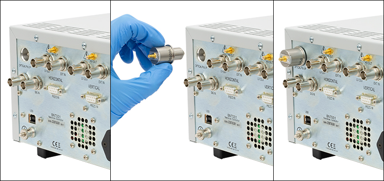
Figure G1.2 コントローラBNT001/IRの左上に取り付けられているディテクタNTA007
Click for Details
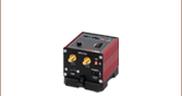
Figure G1.1 コントローラBNT001/IRの左上に取り付けられているSMBコネクタ
NanoTrak®自動アライメントコントローラは、デバイスのアライメント時の結合パワーを最適化します。ピエゾ駆動信号出力は、適切なスループットのために入力・出力デバイスの位置決めに使用されます。900 nm~1700 nm波長用のInGaAsディテクタNTA007とともに発送いたします。ディテクタは3ピン3.5 mmジャックによりユニットの背面に取り付けます。320~1000 nm用SiディテクタNTA009は別売りでご用意しております(下記参照)。コントローラには、PINフォトダイオード型の外付けディテクタの組み込みにご使用いただけるSMBコネクタも付属しています。当社では、長さ914 mmのケーブルPAA236R(SMBメス-BNCオス)を別売りでご用意しております。

 ズーム
ズーム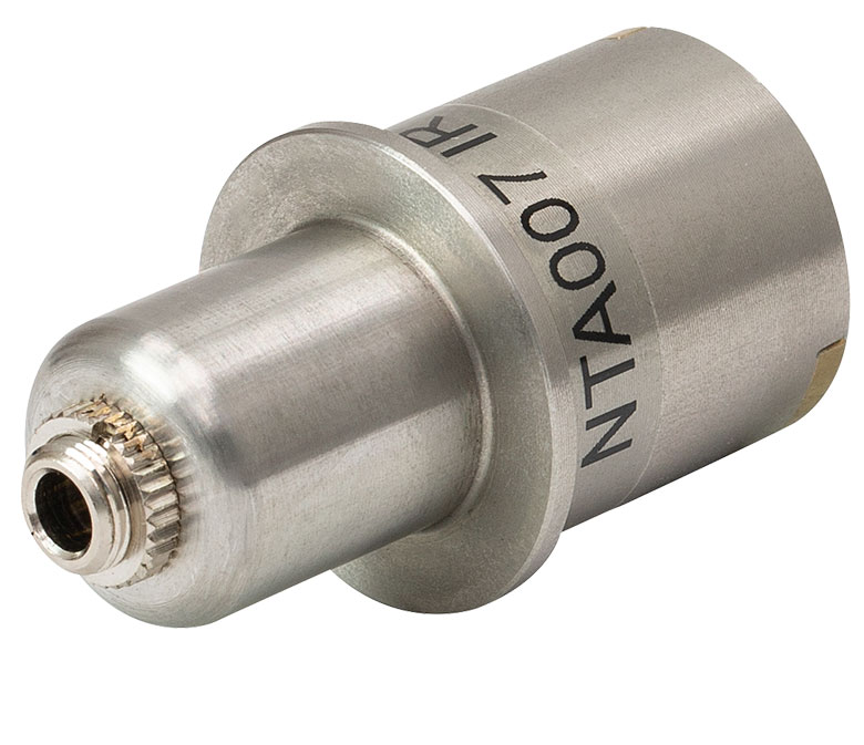 Click to Enlarge
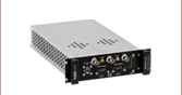
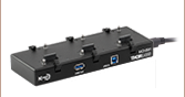
Figure 393A ディテクターヘッドの背面
こちらの赤外(IR)域波長(NTA007)用および可視(VIS)域波長(NTA009)用ディテクターヘッドは、ベンチトップ型(BNT001/IR)、T-Cube™(TNA001/IR、旧製品)、ラックマウント型(MNA601/IR)のNanoTrak®コントローラに対応しています。どちらのディテクターヘッドも背面にFC/PC光ファイバ入力ポートと、ジャックを介してベンチトップコントローラと接続するインターフェイスが付いています(Figure 393A参照)。
| Item # | Wavelength Range | Active Area | Fiber Input | Dark Current | Junction Capacitance |
|---|---|---|---|---|---|
| NTA009 | 320 - 1000 nm | Ø 0.8 mm | FC/PC | 0.01 nA (Typ.) @ 10 V | 3.00 pF(Typ.) @ 10 V |
| NTA007 | 900 - 1700 nm | Ø 0.12 mm | FC/PC | 0.05 nA (Typ.) @ 5 V | 2.0 pF (Typ.) @ 5 V |