 Products Home
モジュール式試験&測定用プラットフォーム

- Modular Platform for Laser Diode Testing and Operation
- Locally Operated Using Built-In Front Panel
- Fast IEEE-488 and RS232 Interfaces for Remote Control
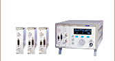
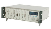
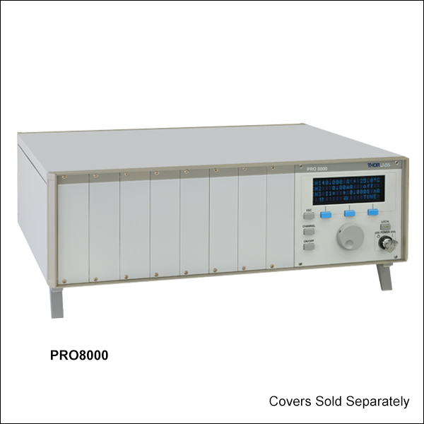
PRO8000
Shown with 8 Installed Modulesand Rack Mounting Adapter
Easy-to-Read Display
No PC Required for Operation
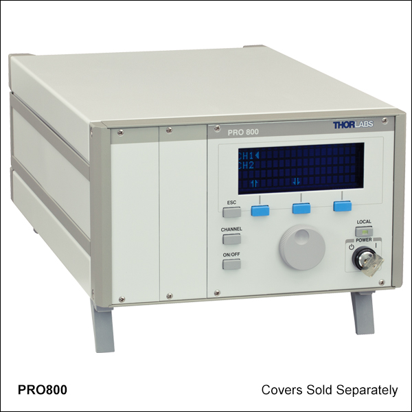
PRO800
2-Slot Benchtop Enclosure,
Shown with PRO8000-C Covers
(Sold Separately)


Please Wait
特長
- 製造・品質管理用の汎用モジュール式プラットフォーム
- 半導体レーザの電流と温度の制御、特性評価やバーンインテスト用途
- WDMレーザ光源、そして製造・品質管理の現場での部品テスト用光学スイッチ等の多様な用途
- コンパクトな2スロット付きベンチトップ型モジュールおよびラックに搭載可能な8スロット付きモジュール
- IEEE 488.2やRS232を介して遠隔制御が可能
- シャーシに付属するアクセサリ
- 電源ケーブル
- マニュアル
当社のPRO8シリーズの試験&測定用プラットフォームは、通信試験などの用途で使われる電気/光学モジュールの操作に使用できます。多くの交換可能なモジュールデバイス(Table 1.1参照)を制御する設計で、外部コンピュータを介せず単独で操作することができます。製品は、2スロット付きベンチトップ型(PRO800)とラックに搭載可能な8スロット付き (PRO8000)の2タイプをご用意しています。8スロット付きシャーシの場合は、19インチラックシステムと組み合わせて使用できます。
モジュール
PRO8シリーズでは、ディスプレイ上のメニューでシャーシ内の全てのモジュールの設定を簡単に行なうことができます。 動作パラメータには覚えやすい記号が割り当てられています。 全ての設定条件は、メモリ内に保存され、電源が切られても他のスロットに移動されない限り、電源再投入時に、自動的に呼び出すことができます。 個々のモジュールは、自動的に認識され、選択時には前面コントロールパネルで、構成と制御が実行できます。
PRO8シリーズのシャーシは、個々の実験ニーズに対応できる設計で、1つずつのモジュールを選択し、カスタム仕様に合わせて構成することができます。 当社ではお客様のニーズに合ったカスタム仕様の構成についてのお手伝いもいたします。製品ご発注前に当社までご相談ください。Table 1.1はご購入可能なモジュールのリストです。 シャーシとモジュールはそれぞれ単体でももご購入いただけます。
PRO8モジュールを当社の半導体レーザーマウントに接続する際には別のケーブルが必要です。 長さが1.5 mのケーブルをご用意しておりますので、必要な場合は、別途ご注文ください。 ピン配列はこのページ下部に掲載されています。
| Item # | PRO800 | PRO8000 |
|---|---|---|
| Number of Slots | 2 | 8 |
| Mains Switch | Key-operated | |
| Remote Control | Via IEEE488.2 and RS232C | |
| Mains Supply | 100 V, 115 V, 230 V (±10%) Fixed (50 to 60 Hz) | |
| Maximum Power Consumption | 220 VA | 500 VA |
| Supply Mains Overvoltage | Category II | |
| Operating Temperature* | 0 - 40 °C | |
| Storage Temperature | -40 to +70 °C | |
| Relative Humidity | Max. 80% up to 31 °C, Decreasing to 50% at 40 °C | |
| Pollution Degree (Indoor Use Only) | 2 | |
| Operation Altitude | < 2000 m | |
| Maximum Output Current per Slot | 4 A | 4 A |
| Maximum Output Current for all Slots | 8 A | 16 A |
| Warm-Up Time for Maximum Accuracy | 10 min | |
| Dimensions (W × H × D) | 232 mm × 147 mm × 396 mm (3 U) | 449 mm × 147 mm × 396 mm (3 U) |
| Maximum Weight | < 9 kg | < 17 kg |
| Display and Operating Elements | ||
| Display | 4 × 20 Characters Alphanumeric Vacuum-Fluorescence-Display | |
| User Interface | Interactive Menus | |
| Keypad | 7 Micro-Switch Keys | |
| Main Tuning Knob | Rotation Encoder | |
| Acoustic Messages | Internal Beeper: Short Tone As Confirmation, Long Tone As Warning | |
| Connectors on the Rear Panel | ||
| Ground | 4 mm Banana Jack | |
| Line | 3-Pin IEC 320 with Fuse | |
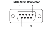
| Remote Control | IEEE488 (24-Pin) Jack or RS-232C (9-Pin) D-Sub Jack | |
| Auxiliary Jack | 9-Pin D-Sub (for Extensions) | |
| Trig In (5 V Max, TTL) | BNC | |
| Trig Out (5 V Max, TTL) | BNC | |
*結露なし
(全技術データは相対湿度 23 ± 5°Cおよび45 ±15%での値です。)
ソフトウェア
バージョン 2.5.3
下のボタンをクリックしてソフトウェアのページにアクセスしてください。
PRO800/PRO8000シリーズ用ソフトウェア
下記のソフトウェアをご提供しております。右のリンクをクリックしてダウンロードいただけます。
- ドライバ:外部ソフトウェアを介してデバイスを直接動作するための装置用ソフトウェアで、お客様固有の要求に合わせて機能性を拡張、またはカスタマイズできます。
- ユーティリティーモジュール:装置の通信機能用のThorlabs Instrument Communicator 2。
| Posted Comments: | |
RWang27
(posted 2017-08-14 14:32:27.443) do u have any sample on how to connect the pro 800 on labview? just like the steps of how to build a connection between labview and pro 800 nreusch
(posted 2017-08-17 06:20:28.0) This is a response from Nicola at Thorlabs. Thank you very much for your inquiry. We do provide the LabVIEW drivers for our PRO800 modules, you can download them at https://www.thorlabs.com/software_pages/ViewSoftwarePage.cfm?Code=PRO8_Series. I will contact you directly to discuss the implementation in your LabVIEW program. user
(posted 2016-11-23 15:36:04.58) Dear Thorlabs,
I'm working with PRO800, LDC8040 and TED8020. Everything is working fine except PC connection. I use Ubuntu 16.04, python 3, pyserial and a USB-RS232-Converter. The connection speed seems a bit slow. I need 0.36-0.52 sec. to read an answer to something like b":LASER?\r\n" and 1.69-1.82 sec. to b":ILD:ACT?\r\n". I tried to use ":SYST:ANSW VALUE", but it didn't make any difference. I also changed baud rates. Is there a way to make it work faster?
With best regards
Mikhail swick
(posted 2016-11-25 05:25:11.0) This is a response from Sebastian at Thorlabs. Thank you for the inquiry.
I would recommend to work via GPIB interface, which should be faster. The speed of communication could be improved by activating the desired slot prior sending the command.
Unfortunately, you did not left any contact details. Please use techsupport@thorlabs.com for getting further technical support. tschalk
(posted 2012-12-13 06:13:00.0) This is a response from Thomas at Thorlabs. Thank you very much for your inquiry. If you are using the "Thorlabs Instrument Communicator" then you can find the instrument by typing "*?" into the suitable field and clicking SCAN CARDS. The PRO800 should appear in the table and you can double click it to make a connection. If you are using an older PRO8 system it will have a female 9-pin D-SUB connector on the rear panel. You should then use an 1:1 connection cable between PRO8 and PC. If you have a newer version with a 9-pin male connector you need a null modem cable shown in the manual on page 18, section 4: Communication with a PC. After the connection is made the window Serial Connection Configuration will appear. Please make sure that the Baud Rate matches with the Baud Rate of the device and select Flow Control RTS/CTS. If you now send the command "*IDN?" the display of the PRO800 should show "REMOTE" and you should receive a response like "Throlabs, Pro800, ...". If you type in for example ":SLOT 1" the green light beside SEL of Channel 1 should light up. If you don’t get any response then please make sure that you are using the correct type of interconnecting cable. carbonem
(posted 2012-12-12 07:05:39.85) Dear Sirs:
Recently we acquired a module controller based on a PRO800 chassis with a PDA8000-2 module for optical power measurement. By now it is connected to a high-speed photodetector DET36A/M.
We are trying to connect the controller to a PC by using an RS232 serial cable and to control the system in remote mode. However we are not able to communicate both devices properly. Therefore, to check the connection we are using your software “Thorlabs Instrument Communicator”.
The COM port flow control of our PC can be selected as “none”, “hardware” or “XON/XOFF”. However your software indicates that we must activate the “RTS /CTS” mode.
So far we have managed to send commands and to change the controller mode from local to remote or remote to local (to this end, we select the flow control mode in “none” or “disabled”). However but we do not receive a response back from the controller when we send request commands. Apparently, data travels from the PC to the controller, but not from the controller to the PC.
Please, could you give us any suggestion to get the connection in both directions?
Should we select a different flow control mode on the COM port?
Thank you very much in advance for your help.
Best regards, Laurie
(posted 2008-10-02 09:03:06.0) Response from Laurie at Thorlabs to edu6182: Thank you for your interest in our PRO800. The system comes with LabVIEW and CVI drivers on a CD ROM. Alternatively, you can download the files here: http://www.thorlabs.com/Support.cfm?Section=7&viewTab=1
Use the "Custom Installation" to add LabVIEW, LabWindows, and C++ drivers. edu6182
(posted 2008-09-30 08:08:23.0) Dear Sirs,
This is Enric Donés, an engineer from National Microelectronic Center in Barcelona (Spain). I need to use a PRO800 optical source for making some tests and I would like to know if there are available Labview drivers to control this device from a PC.
Thank you for you help.
Regards,
Enric Donés. |

 ズーム
ズーム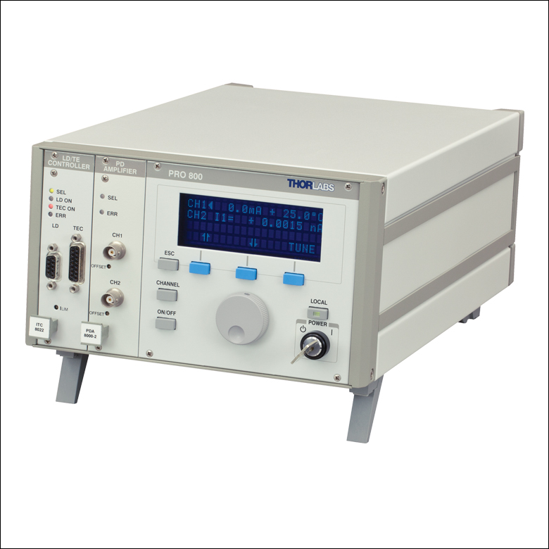 Click to Enlarge
| Key Specifications | ||||
|---|---|---|---|---|
| Number of Slots | 2 | |||
| Max Power Consumption | 220 VA | |||
| Max Output Current Per Slot | 4 A | |||
| Max Output Current for All Slots | 8 A | |||
- コンパクトタイプの2スロット付きベンチトップ型シャーシ
- 研究開発に適した製品
- 多くの温度/電流コントローラや光スイッチと併用可能
- 寸法(W×H×D) 232 mm x 147 mm x 396 mm (3 U 高さ)
シャーシPRO800は、研究室内でご使用いただくのに適した製品で、最大2個のモジュールが収納できます。 このシャーシには、カスタム仕様に合わせて2個のモジュールが収納可能で、ご購入前に実験用途に最も適した構成をご注文いただくことができます(Figure G1.1参照)。 またこのシャーシは空の状態でご注文いただくこともできます。その場合、左の写真のようにPRO800の空のスロットは、輸送中の保護にフロントカバープレートPRO8000-C(別売り。下記参照)でカバーすることができます。

 ズーム
ズーム Click to Enlarge
| Key Specifications | ||||
|---|---|---|---|---|
| Number of Slots | 8 | |||
| Max Power Consumption | 500 VA | |||
| Max Output Current Per Slot | 4 A | |||
| Max Output Current for All Slots | 16 A | |||
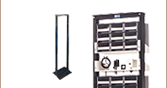
- ラックに搭載可能な8スロット付シャーシ
- 大規模な試験や工場での使用に適した製品
- 多くの温度/電流コントローラや光スイッチと併用可能
- 寸法(W×H×D):449 mm x 147 mm x 400 mm (3 U 高さ)
シャーシPRO8000には最大8個のモジュールが収納可能で、大規模な試験に適した製品です。このシャーシには、カスタム仕様に合わせて8個のモジュールが収納可能で、ご購入前に個別の実験用途に最も適した構成をご注文いただくことができます(Figure G2.1参照)。またこのシャーシは空の状態でご注文いただくこともできます。その場合、配送時にはフロントカバープレートPRO8000-C(別売り。下記参照)を使用してPRO8000の空のスロットを保護することができます。
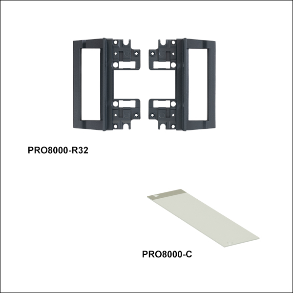
Figure G2.1のように、別売りのラック取付け用ハンドルPRO8000-R32をシャーシに取り付けて19インチラックシステムに統合することができます。

 ズーム
ズーム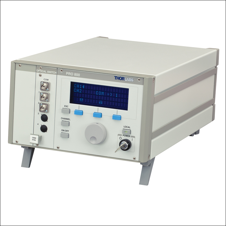 Click to Enlarge
マウントキットPRO8000-R32に付属するハンドル1対により、シャーシPRO8000を19インチラックシステムに取り付け可能です。ハンドルを取り付けるには、PRO8000の筐体を取外し、再び組み立てる必要があります。ハンドルは筐体に付いていたネジを使用してユニットに固定します。シャーシPRO8000と同時にハンドルが付属するPRO8000-R32をご注文いただけると、ラックマウントを取り付けた状態で製品をお届けします。その後シャーシをラックシステムに取り付けるには、貫通穴を使用します。なお、PRO800にもマウントキットPRO8000-R32をご使用いただけますが、19インチラックシステムに収めるには幅が狭くなっています。
フロントカバープレートPRO8000-CはシャーシPRO800と PRO8000の空いているスロットを保護するために使用します。取り付けるには、モジュールをシャーシに固定する際に使用された2個のプラスのネジをご使用下さい。取付方法はモジュールと同様です。Figure G3.1では、シャーシPRO800にフロントプレートPRO8000-C 1枚が取り付けられています。

 ズーム
ズーム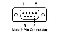
ケーブルCAB400を使用して、当社の半導体レーザ電流コントローラーモジュールと半導体レーザーマウントを接続できます。
| CAB400 (9 Pin Male) Cable | |
|---|---|
| Pin # | Description |
| 1 | Interlock and Status LASER ON/OFF |
| 2 | Photodiodea |
| 3 | Laser Diode Ground |
| 4 | Photodiodeb |
| 5 | Ground for Pin 1 |
| 6 | Voltage Measurement Laser Diode Cathodec |
| 7 | Laser Diode Cathode (with Polarity Anode Grounded - AG) |
| 8 | Laser Diode Anode (with Polarity Cathode Grounded - CG) |
| 9 | Voltage Measurement Laser Diode Anodec |

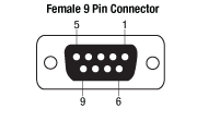
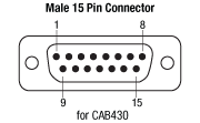
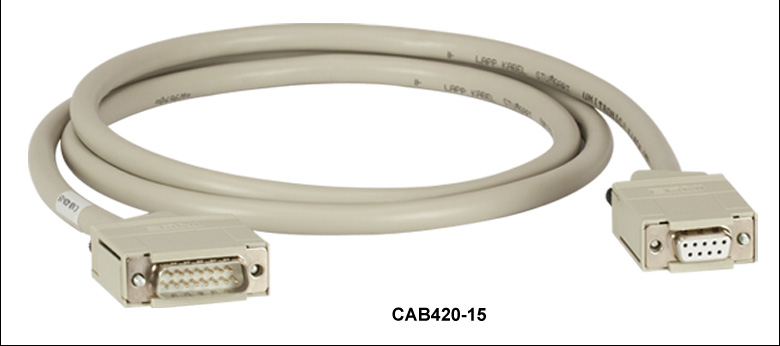 ズーム
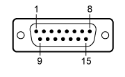
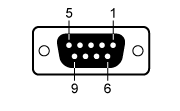
ズームケーブルCAB420-15を使用して、当社の温度コントローラーモジュールと半導体レーザーマウントを接続できます。Table G5.1とG5.2は当社の半導体レーザ用温度コントローラおよび半導体レーザーマウントで使用されている典型的なピン配列を示しています。Table G5.3はケーブルCAB420-15の15ピン側と9ピン側の物理的なピン接続を示しています。
| Table G5.1 Male 15-Pin Connector | |
|---|---|
 | |
| 1 | Status LED (+) (for TEC On/Off Indication)a |
| 2 | TEC Voltage Measurementb |
| 3 | Thermistor (-), Ground |
| 4 | Thermistor (+) |
| 5 | TEC (+) |
| 6 | TEC (+) |
| 7 | TEC (+) |
| 8 | LM 135/335 (-), Grounda |
| 9 | TEC Voltage Measurementb |
| 10 | Transducer AD 590/592 (-), LM 135/335 (+) |
| 11 | Transducer AD 590/592 (+), LM 135/335 (+) |
| 12 | No Connection |
| 13 | TEC (-), Status LED (-) |
| 14 | TEC (-), Status LED (-) |
| 15 | TEC (-), Status LED (-) |
| Table G5.2 Female 9-Pin Connector | |
|---|---|
 | |
| 1 | Status LED (+) (for TEC On/Off Indication)a |
| 2 | Thermistor (+) |
| 3 | Thermistor (-), Ground |
| 4 | TEC (+) |
| 5 | TEC (-), Status LED (-) |
| 6 | No Connection |
| 7 | Transducer AD 590/592 (-), LM 135/335 (+) |
| 8 | LM 135/335 (-), Grounda |
| 9 | Transducer AD 590/592 (+), LM 135/335 (+) |
| Table G5.3 Pin Connections | |
|---|---|
| 15-Pin Side | 9-Pin Side |
| 1 | 1 |
| 2 | 4 |
| 3 | 3 |
| 4 | 2 |
| 5 | 4 |
| 6 | 4 |
| 7 | No Connection |
| 8 | 8 |
| 9 | 5 |
| 10 | 7 |
| 11 | 9 |
| 12 | No Connection |
| 13 | 5 |
| 14 | 5 |
| 15 | No Connection |

 ズーム
ズームケーブルCAB430を使用して、当社の半導体レーザ電流&温度コントローラーモジュールと半導体レーザーマウントを接続できます。
 | |
Pin Connections |
 | |
Pin Connections |
 | |
Pin Connections |