 Products Home
高性能4チャンネルLEDドライバ
- Controls a Four-Wavelength LED4D Source or Four Individual LEDs
- LED Current Range: 0 to 1000 mA
- LED Current Accuracy: ±10 mA
- Modulation Frequency: 0 to 100 kHz
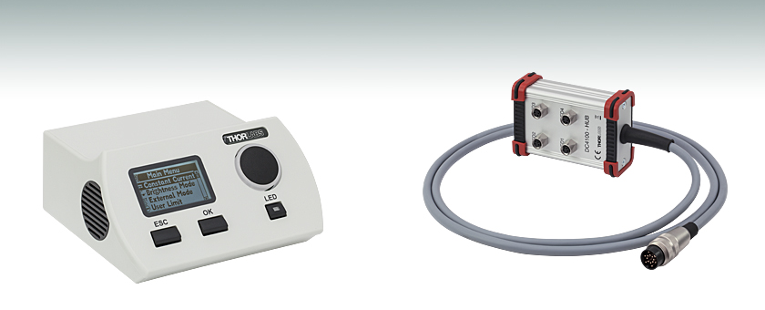
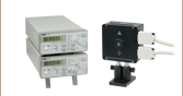
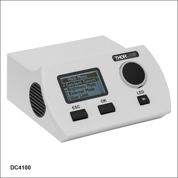
DC4100
4 Channel LED Driver
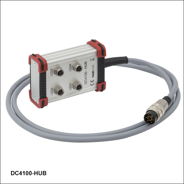
DC4100-HUB
Optional Hub for
Four Individual LEDs


Please Wait
| Key Specifications | ||
|---|---|---|
| Item # | DC4100 | DC4104 |
| LED Current Range | 0 - 1000 mA | |
| LED Current Resolution | 1 mA | |
| LED Current Accuracy | ±10 mA | |
| LED Forward Voltage | 5 V | |
| Modulation Frequency Range | 0 - 100 kHz, Sine Wave | |
| Modulation Voltage | 0 - 10 V | |
| Trigger Input Channels | 1 | 4 |
用途
- 4波長のLED光源用のドライバ: LED4Dシリーズ
- 複数の波長を利用する蛍光顕微鏡法
Click for Details
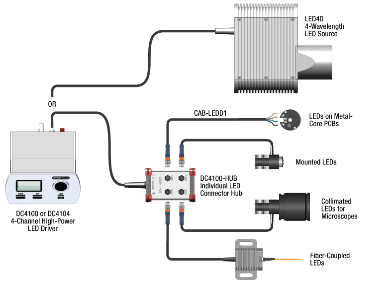
LEDドライバDC4100やDC4104は様々な構成にご使用になれます。
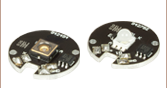
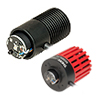
当社の 4波長LED光源 はDC4100またはDC4104を直接取り付けられます。 ファイバ出力型、コリメートならびに ヒートシンクマウント済みLEDはDC4100-HUBが必要です。 メタルコアPCB基板実装済みLED は、上の写真のとおりDC4100-HUBならびにCAB-LEDD1ケーブルでご使用になります。
特長
- 4チャンネルで、電流の個別調整可能
- 1変調信号入力(DC4100)または4変調信号入力(DC4104)から選択
- 変調信号入力は分解能1 msの速い切り替え時間
- 直線電流源は信頼性と再現性が高い信号を供給
- リモートコントロール用USB 2.0インターフェイス
- µManager Automation Suiteと互換性あり
- 波長や変調の特注も可能
当社の4チャンネルLEDコントローラDC4100およびDC4014は、顕微鏡のほか複数のカラーチャンネルを利用する用途向けに設計されました。4波長LED光源LED4Dシリーズに適したドライバです。DC4100-HUBを介して当社のマウント済みLED(コリメート/非コリメート)などの高出力LEDを4つ同時に駆動することができます。コネクターハブDC4100-HUBと、接続ケーブルCAB-LEDD1を4本使用することによって、当社のメタルコアPCB基板実装済み高出力LED やお手持ちのLED4台がご使用になれます(右の図をご覧ください)。各チャンネルのLED電流は、 0~1000 mAの間で独立して調整可能で、外部電圧印加により同時変調もできます。詳しくは下記「動作モード」をご覧ください。
コントローラの筐体はコンパクトで、バックライト式の見やすいLCDディスプレイが付いています。前面パネルのホイール型セレクタと3つのボタンで操作します。また、どちらのLEDドライバもUSB2.0を介して遠隔操作が可能で、そのためのソフトウェアは「ソフトウェア」タブからダウンロードできます。このソフトウェアには直感的なGUIとドライバのセットが付いています。これらのLEDドライバは、多目的に使える自動操作顕微鏡用のオープンソースGUIソフトウェアプラットフォームµManagerにも対応します。プラグインタイプなので、すぐにLEDドライバの制御にご使用いただけます。
動作モード
- 定電流モード: LED電流をmAレベルの値で設定された電流値に保ちます。一般的な用途には、このモードが適します。
- 輝度モード: LED電流を最大電流に対する割合(%)で設定して制御します。蛍光顕微鏡の用途に適しています。
- 外部制御モード:LED電流は信号発生器(付属していません)からの外部トリガで変調できます。コントローラDC4100では、駆動している全てのLEDを同じ変調信号で制御しますが、個別にLEDをオフにすることは可能です。コントローラDC4104では、各LEDをそれぞれ独立の変調信号で制御しますが、それらの全ての信号は付属の1本のケーブルを通じて供給されます。どちらのコントローラも変調信号の入力電圧範囲は0~10 Vで、1 VはLED電流100 mAに対応します。
| LED Options | ||
|---|---|---|
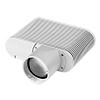 |  | 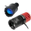 |
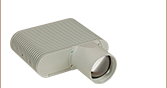
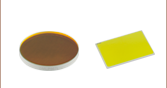
| Four-Wavelength LED Source | Fiber-Coupled LEDsa | Collimated Microscope LEDsa |
 |  |  |
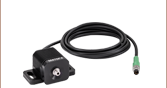
| Mounted LEDsa | Diffuse Backlight LEDa | PCB-Mounted LEDsb |
| LED Controller Selection Guide | ||||||
|---|---|---|---|---|---|---|
| Type | Max Number of LEDs | Max Current | Modulation Mode | USB | Remote Operation | Compatible LEDs |
| upLED™ LED Driver | 1 | 1.2 A | - | Yes | Yes | Mounted, Collimated, Fiber Coupled, Diffuse Backlight, and, PCB Mounteda |
| Compact T-Cube™ Driver | 1 | 1.2 A | 0 - 5 kHz | No | No | |
| 4-Channel Driver | 4 | 1 A | 0 - 100 kHz | Yes | Yes | |
| 4.0 A LED Driver | 1 | 4.0 A | 0 - 5 kHz | Yes | Yes | |
| Solis® LED Driver | 1 | 10 A | 0 - 1 kHz | No | No | High Power |
| High-Power Touchscreen Drivers | 1 | 10.0 A | 0 - 250 kHz | Yes | Yes | High Power, Mounted, Collimated, Fiber Coupled, Diffuse Backlight, and, PCB Mounteda |
| Item # | DC4100 | DC4104 |
|---|---|---|
| Constant Current Mode | ||
| LED Current Range | 0 - 1000 mA | |
| LED Current Resolution | 1 mA | |
| LED Current Accuracy | ±10 mA | |
| LED Forward Voltage | 5 V | |
| Brightness Mode | ||
| LED Current Range | 0 - 100% | |
| LED Current Resolution | 0.1 % (min. 1 mA) | |
| LED Current Accuracy | ±10 mA | |
| LED Forward Voltage | 5 V | |
| External Control Mode | ||
| Modulation Frequency Range | 0 - 100 kHz, Sine Wave | |
| Modulationa | Arbitrary | |
| Trigger Input Channels | 1 | 4 |
| Trigger Input (Maximum) | 10 V 1 V corresponds to 100 mA | |
| General | ||
| Operating Temperature Rangeb | 0 to 40 °C | |
| Storage Temperature Range | -40 to 70 °C | |
| Dimensions (W x H x D) without Operating Elements | 160 mm x 80 mm x 150 mm | |
| Dimensions (W x H x D) with Operating Elements | 160 mm x 80 mm x 168 mm | |
| Warm Up Time for Rated Accuracy | < 10 min | |
| Weight | < 1 kg | |
DC4100前面パネル
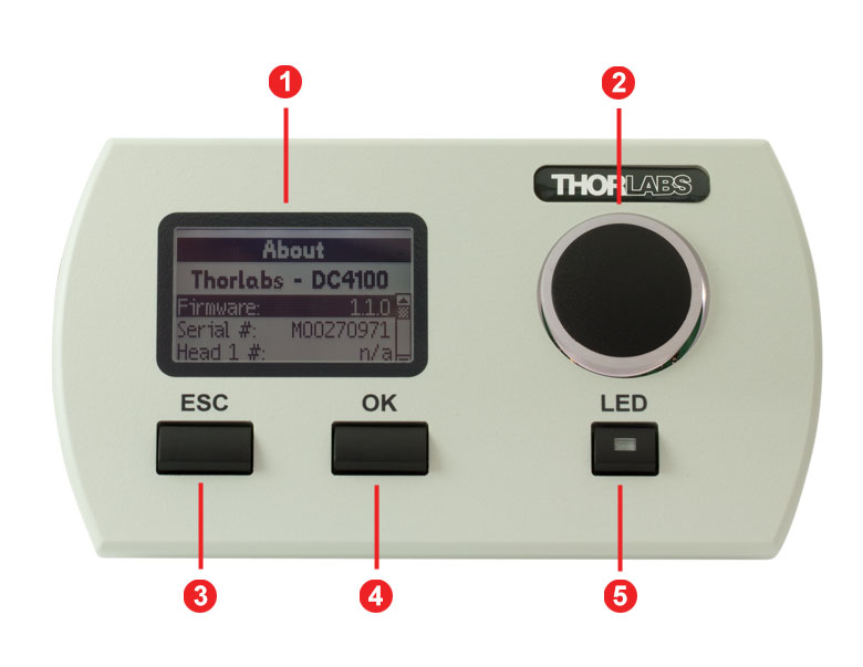
| Callout | Connection | Callout | Connection |
|---|---|---|---|
| 1 | Display | 4 | OK Button |
| 2 | Display Control Knob | 5 | LED On/Off Button |
| 3 | Escape Button |
DC4100背面パネル
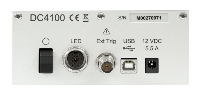
| Callout | Connection | Callout | Connection |
|---|---|---|---|
| 1 | Serial Number of the Unit | 4 | External Trigger Input (BNC) |
| 2 | Power Switch | 5 | USB Connector |
| 3 | LED Connectora | 6 | Voltage Supply Connector |
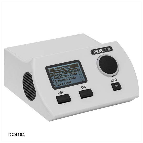
DC4104前面パネル
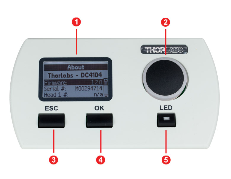
| Callout | Connection | Callout | Connection |
|---|---|---|---|
| 1 | Display | 4 | OK Button |
| 2 | Display Control Knob | 5 | LED On/Off Button |
| 3 | Escape Button |
DC4104背面パネル
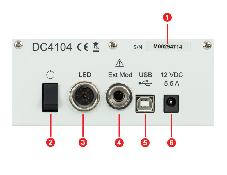
| Callout | Connection | Callout | Connection |
|---|---|---|---|
| 1 | Serial Number of the Unit | 4 | External Trigger Input (8-Pin Push/Pull) |
| 2 | Power Switch | 5 | USB Connector |
| 3 | LED Connectora | 6 | Voltage Supply Connector |
高性能4チャンネルLEDドライバDC4100シリーズ用ソフトウェア
下記のソフトウェアをご提供しております。
- ソフトウェア:標準的な用途においてデバイスを操作する時のソフトウェアとドライバのパッケージ、グラフィカルユーザーインタフェイス付き。パッケージには、LabVIEW™/CVIおよびLabVIEW™ National Instruments™開発環境向けの計測器ドライバも付属しています。
- ファームウェア:LEDドライバDC4100およびDC4104用の最新のファームウェアバージョン。インストール手順についてはユーザーマニュアルをご覧ください。
- アーカイブ:旧バージョンのDC4100およびDC4104用ソフトウェア
ソフトウェア
ソフトウェア バージョン 2.3
DC4100およびDC4104用ソフトウェアパッケージ
DC4100&DC4104 LEDの接続(14ピン、M16メス型)
下の表にあるLED 1、LED 2、LED 3、LED 4は、短波長から長波長の順に、 LED4D光源に搭載されるLEDを示しています。
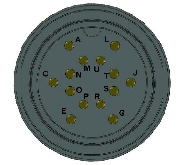
| Pin | Description | Comment |
|---|---|---|
| A | LED 1 Anode | |
| C | LED 1 Cathode | |
| E | LED 2 Anode | |
| G | LED 3 Anode | |
| J | LED 3 Cathode | |
| L | LED 4 Anode | |
| M | LED 1 1 Wire EEPROM I/O | Do Not Use |
| N | DGNG | Do Not Use |
| O | LED 2 1 Wire EEPROM I/O | Do Not Use |
| P | LED 2 Cathode | |
| R | LED 3 1 Wire EEPROM I/O | Do Not Use |
| S | DGNG | Do Not Use |
| T | LED 4 1 Wire EEPROM I/O | Do Not Use |
| U | LED 4 Cathode |
DC4100外部トリガ
BNCメス型
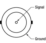
0~10 V、0~100 kHz外部LED制御
DC4104外部トリガ
 オス型8ピン プッシュプルコネクタ | Pin | Description | Bare Wire Color |
|---|---|---|---|
| 1 | LED Channel 1 | Pink | |
| 2 | GND | Green | |
| 3 | LED Channel 2 | Blue | |
| 4 | GND | Red | |
| 5 | LED Channel 4 | Brown | |
| 6 | GND | Yellow | |
| 7 | LED Channel 3 | Gray | |
| 8 | GND | White |
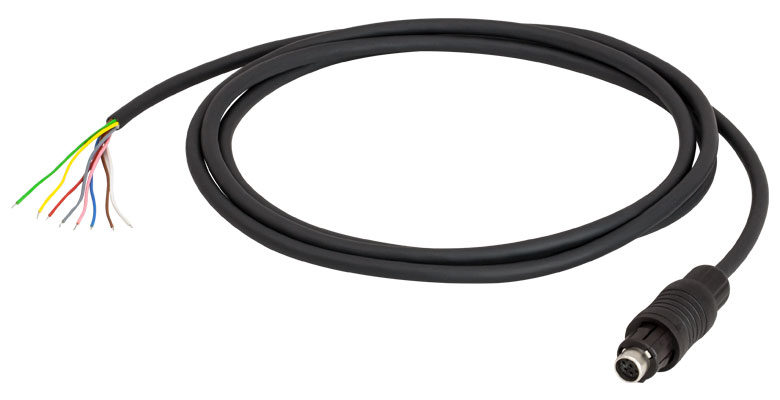
上は外部変調用ケーブルDC4104のオス型コネクタです。
すべての接地ワイヤは共通の接地を使用しています。
DC4100-HUB LED接続
 Female M8x1 Connector | Pin | Description |
|---|---|---|
| 1 | LED Anode | |
| 2 | LED Cathode | |
| 3 | EEPROM GND | |
| 4 | EEPROM IO |
上の図はDC4100-HUBのメス型コネクタ(標準のM8x1センサ円形コネクタ)です。ピン1と2はLEDとの接続用です。ピン3と4は内部EEPROM用なので、ご使用にはならないでください。
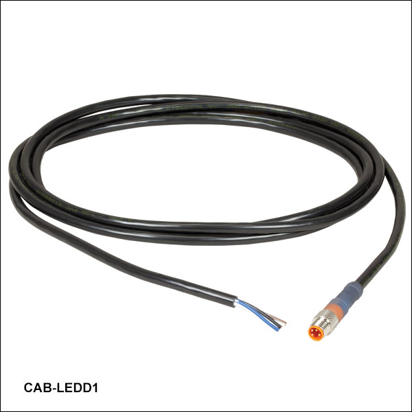
CAB-LEDD1 LED接続
 Male M8x1 Connector | Pin | Description | Wire Color |
|---|---|---|---|
| 1 | LED Anode | Brown | |
| 2 | LED Cathode | White | |
| 3 | EEPROM GND | Black | |
| 4 | EEPROM IO | Blue |
上の図はCAB-LEDD1のオス型コネクタ(標準のM8x1センサ円形コネクタ)です。ピン1と2はLEDとの接続用です。ピン3と4は内部EEPROM用なので、ご使用にはならないでください。
| Posted Comments: | |
Jean D
(posted 2025-03-06 14:56:48.213) hello,
same problem :
I want use the PC app to control the LEDs. Windows recognizes the hardware ( " USBtoDC4104 Bridge" )and assigns a com port, but the app is not detecting anything !
Any clue whatt could cause this? hkarpenko
(posted 2025-03-07 07:43:03.0) Dear customer,
thank you very much for your feedback. A quick solution could be to deinstall the drivers manually and reconnect the device. I will contact you directly to assist you further on this. user
(posted 2023-05-25 09:14:32.467) Hello. We want to use the PC app to control the LEDs. Windows recognizes the hardware and assigns a com port, but the app is not detecting anything. We tried reinstalling a few times, rebooting, and installing and older version. We have windows 10. Any clue whatt could cause this? hchow
(posted 2023-06-02 09:41:37.0) Dear User, thank you for your feedback. We are currently looking into this. I will contact you personally to offer technical support. Thank you. David Mayerich
(posted 2023-01-13 11:37:46.347) Is there any way to get C/C++ drivers for this? I have to control the LEDs using some existing controller software.
Thanks!
David wskopalik
(posted 2023-01-16 04:42:39.0) Thank you very much for your feedback!
The driver files are included in the software installation package which you can download in the “Software” tab. The package includes all the necessary DLL and header files.
I will contact you directly to provide further information. Brian A
(posted 2021-09-08 10:40:39.943) We have a Thorlabs DC4100 four channel LED device.
I’m a software engineer interface with this device using C# .NET 4.8
I downloaded the driver and example code from here:
https://www.thorlabs.com/software_pages/viewsoftwarepage.cfm?code=DC4100
The download only included x86 (32 bit) support. I interface through the dll file called
Thorlabs.DC4100.Interop.dll
File version 1.3.04
Can you tell me where the x64 (64 bit) support is located?
Thanks.
B. wskopalik
(posted 2021-09-16 08:00:45.0) Thank you very much for your inquiry!
The 64-bit dll file for .NET can be found in this folder when the software package 2.2 from our website is installed:
C:\Program Files\IVI Foundation\VISA\VisaCom64\Primary Interop Assemblies Sven Schörnich
(posted 2021-04-15 10:19:16.37) Ich frage mich, welche Stromstärken/lasten der Eingang für den Externen Control mode aushält? Das Steuersignal kann bis zu 10V haben, aber wie sieht es mit dem Eingangswiderstand des DC4104 aus? Welche Ströme können hier fliessen, wenn ich einen Verstärker vorschalten muß um aus max. 1,4V Steuersignal auf die finalen 10V zu kommen? MKiess
(posted 2021-04-19 07:54:07.0) Dear Sven, thank you very much for your inquiry. You should only apply a voltage between 0 and 10V to the external trigger input. The current flows here depending on the applied voltage. It is therefore important to know that a voltage of 1V applied to the external trigger input corresponds to a current of 100mA at the LED output. Patrick Fumo
(posted 2020-08-03 11:24:24.44) To whom it may concern,
Is there anyway I can get a more detailed document that describes the TLDC4100_32.dll? I need to be able to control some LEDs from a custom application but the current DC4100 Manual does not give enough information to write the code for such an interface. Thank you.
Best Regards,
Patrick Fumo MKiess
(posted 2020-08-04 04:33:23.0) Dear Patrick, thank you very much for your inquiry. In the following folder, which is included in the software download, you can find a Programmer's Reference, in which all functions are explained in detail.
C:\Program Files\IVI Foundation\VISA\WINNT\Thorlabs DC4100 Series\Manual Ralph Savioli
(posted 2020-03-17 16:59:07.053) This question is for the DC2100, but if the DC4100 has the same spec then all the better:
What is the delay time from an external trigger to the LED drive output? At both turn-on and turn-off when running in External mode.
I'm doing some time critical measurements synchronized to a CMOS imager and need to know this parameter. The spec only give the Rise/fall time - which is slightly different. nreusch
(posted 2020-03-26 03:32:27.0) This is a response from Nicola at Thorlabs. Thank you very much for your feedback. The delay of an LED with respect to the external trigger input depends on several factors: The capacity of the LED itself, cord capacities as well as drive current and modulation frequency. While we cannot specify a specific value for neither DC2100 nor DC4100, I will contact you directly to send you some exemplary measurements. Khoa Nguyen
(posted 2020-02-17 14:09:53.887) Can you make more than 4 channel LEDs, such as a custom number of channels? dpossin
(posted 2020-02-19 06:02:56.0) Dear Customer,
Thank you for your feedback. Unnfortunately we can not increase the number of channels for our DC4100 LED controller but we recently released a 6 wavelength source. You can have a look here: https://www.thorlabs.com/newgrouppage9.cfm?objectgroup_id=13597. Gary Yellen
(posted 2019-07-10 17:07:34.763) I purchased this item together with my Bergamo laser scanning microscope. I have downloaded the GUI, but would really like to control this in coordination with my TSI Quantalux camera. It doesn't appear there is any native support for the LED controller in ThorimageLS.
Is there an SDK (or at least documentation on the USB command stream) that would allow me to control this device from MATLAB? dpossin
(posted 2019-07-17 09:12:34.0) Dear Gary,
Thank you for your feedback,
It is not possible to controll the DC4104 from the Thorcam software but the Quantalux as well as the DC4104 can be triggered externally. You can feed a TTL signal from an external source into the camera and the LED driver in order to synchronize them.
The SDK files and the corresponding API you can find in the corresponding folder "Scientific Camera Interfaces". a woehl
(posted 2019-07-02 12:23:58.37) Hi, We are have some troubles getting the DC4104 to work with uManager (Win10). We have installed the most recent version of the control software (v2.2), yet when we run the hardware configuration wizard in uManager we see ThorlabsDCxxxx (unavailable). Any ideas? Perhaps we need a previous driver version for the uManager device adapter? Many thanks for your help!!! MKiess
(posted 2019-07-04 10:45:17.0) This is a response from Michael at Thorlabs. Thank you very much for your inquiry! The DC4104 is compatible with Windows 10 and MicroManager. If the DC4104 LED drivers are installed correctly and are shown in the Windows device Manager, you can install the DC-LED-drivers in MicroManager. I will contact you directly for further assistance. tou-cheu.xiong
(posted 2017-12-01 19:20:11.23) Hi
we have purchased the controller DC4104 and we would like to plug a LED strip. Unfortunate the controlleur could not identify any LED. Could you please let me know if it is possible to connect a LED strip (only anode and cathode) to this controller?
Thank you swick
(posted 2017-12-05 03:50:54.0) This is a response from Sebastian at Thorlabs. Thank you for the inquiry. Compatibility to DC4104 depends on properties of the LED like forward voltage and electrical current. I have contacted you directly for assistance. user
(posted 2017-10-26 15:36:36.797) Hi,
Is there a way to program directly the DC4104? I couldn't find any API for thhis controller.
Of course there is the option to control the LEDs via the external trigger but I would like to be able to also change/select the channels (LEDs) that are under the external control. That's also because every time the device is switched off and on I have to manually re-select the active LED.
Thanks,
Daniel wskopalik
(posted 2017-10-27 07:28:31.0) This is a response from Wolfgang at Thorlabs. Thank you very much for your inquiry.
The DC4100 and DC4104 can be controlled using the driver files available in the tab "Software" of this website. These files include a documentation of the driver commands as well as some example codes.
Unfortunately, you didn't leave an email address but please feel free to contact me any time at europe@thorlabs.com. simon.walker
(posted 2017-08-11 17:54:37.943) I would like to use the DC4100 with some high speed cameras. The cameras will be running at about 4Khz, with 10% duty cycle (i.e. an exposure time of 25us). They produce a 5V ttl pulse output, which is high during the exposure and low (0V) at other times. Can this be used to sync the DC4100 so that the LEDs turn on during the exposure and are off at other times?
Thanks,
Simon nreusch
(posted 2017-08-17 06:13:12.0) This is a response from Nicola at Thorlabs. Thank you very much for your inquiry. The DC4100 is suitable for an external trigger input up to 10 V and a modulation frequency range of 0 to 100 kHz for sine wave modulation. So you could use a 5 V TTL pulse with 4 kHz repetition rate. Please note that 1 V of the trigger input signal will correspond to 100 mA, so 5 V equal 500 mA. In order to decide whether the DC4100 would really meet your requirements, I will also contact you directly to discuss your application in more detail. kkomar
(posted 2017-05-29 14:57:21.033) I'm planning to use DC4100 with one of the diodes: MNWHL4 or MWWHL4 to switch on one them for relatively short time (50 us to 500 us) but with extremely low frequency (0.2 to 0.01 Hz). If the modulation signal of such low duty cycle will be connected with the trigger input of the DC4100 what would be main limiting factor: LED or the driver? Where can I check the rising time of Thorlabs LEDs? swick
(posted 2017-06-01 03:42:42.0) This is a response from Sebastian at Thorlabs. Thank you for the inquiry.
The bandwidth of DC4100 is 0 - 100 kHz, small-signal, sine wave.
If modulating with a waveform other than sine wave, the functional bandwidth will be reduced. I will contact you directly to discuss your application in detail. l.volkers
(posted 2017-01-31 04:41:09.943) I've read the software manual and it's not clear to me, whether there is a possibility to use the DC4104 as a pacing device. And if so, which additional devices/cables/software would be best functioning in combination with this device?
Best regards,
Linda wskopalik
(posted 2017-02-01 03:55:05.0) This is a response from Wolfgang at Thorlabs. Thank you very much for your inquiry.
The DC4104 can be externally modulated up to 100 kHz with a sine wave signal. The current applied to the connected LEDs will be modulated corresponding to the applied signal.
I will contact you directly to discuss your requirements and to provide further assistance. sergio.sigala
(posted 2016-08-23 12:41:52.15) Hello, may I have the TARIC code (Tariff Number) for this product?
Thank you swick
(posted 2016-08-26 02:13:13.0) This is a response from Sebastian at Thorlabs. Thank you for the inquiry. We will contact you directly about Tariff codes. banhuat.khor
(posted 2016-06-23 02:40:05.613) There are few systems in production using DC4100, we are facing intermittence LED light off in one of the channel (i.e always channel 1).
We have swapped the DC4100, but the problem still remain the same.
For recovery, we have to power cycle the DC4100.
Does your site have any advice for this issue ? What could have caused this LED light off.
Thanks.
Best rgds;
Mr Khor. shallwig
(posted 2016-06-23 06:44:24.0) This is a response from Stefan at Thorlabs. Thank you for contacting us and please apologize the problems you face with your DC4100 units. I have contacted you directly for troubleshooting this in detail. alexandr.erofeew
(posted 2016-03-28 12:50:31.117) Hi,
We have thorlabs DC2100 and DC4104, the question is, where we can find externel mode cable for DC4104?
Can we use Pulse Width Modulation Mode on DC4104 (some programm patch or new firmware)
Best regards. shallwig
(posted 2016-03-29 10:10:09.0) This is a response from Stefan at Thorlabs. Thank you very much for your inquiry. Unfortunately from the hardware side a PWM mode cannot be implemented into the DC4100/DC4104 drivers. Modulation can only be done externally with the cable we ship with each unit. I will contact you directly to offer you a replacement cable. emazy
(posted 2015-03-02 15:15:03.22) Dear Sir,
I desire to know the stability of the current over 60 sec range ?
Thank a lot in advance tschalk
(posted 2015-03-05 10:29:58.0) This is a response from Thomas at Thorlabs. Thank you very much for your inquiry. We recommend a warm up time of about 10 minutes, and after that the unit reaches the highest stability. The accuracy of the driver is +/-10mA but the stability will be much better, however we do not have specific measurement results for that. I will contact you directly with more detailed information. p.donn
(posted 2014-12-03 09:35:38.0) Hello,
is there any matlab support given for this product?
Best regards shallwig
(posted 2014-12-03 04:15:01.0) This is a response from Stefan at Thorlabs. Thank you very much for your inquiry. At the moment there are no Matlab support documents available for this LED driver. We will contact you directly for discussing your request in detail. user
(posted 2013-09-27 10:51:25.103) Dear Sirs,
I would like to know the time resolution in the External Control Mode. And could we apply "sine waves" or any waves in the External Control Mode?
Thank you.
SunJ jvigroux
(posted 2013-09-27 08:03:00.0) A response from Julien at Thorlabs: The time resolution of the analog circuit used for the external voltage control is extremely low but the limiting factor for fast application is normally the rise time of the output stage driving the LEDs. This time is usually in the low µs range (the exact value varies from LED to LED). Any type of modulation (sine, square, triangle etc.) can be applied to this input provided of course that the driving signal is not faster than the above mentioned rise time. jlow
(posted 2012-11-13 09:00:00.0) Response from Jeremy at Thorlabs: You can modulate the brightness of 4 LEDs individually using the DC4104. The 8-pin cable is provided (with open wiring on one end). eozkan
(posted 2012-11-12 20:33:07.027) Hello,
I have a question about DC4104 driver. Can I modulate the brightness of each of 4 LED externally using this driver? Do you provide necessary cables? jvigroux
(posted 2011-07-06 11:26:00.0) A response form Julien at Thorlabs: Dear Niccolo, thank you for your feedback! We are about to release a new version of the DC4100 driver that allows its operation on 64bits system. I will contact you directly to send you the installer. This version should be online within the next couple of weeks. banterle
(posted 2011-07-05 03:03:12.0) Dear customer service, I was using the dc4100 (which is great) succesfully controlling it from labview untill some days ago. Then we swapped to a 64 version of labview and the libraries are not considered valid anymore, is there a 64bit version of the drivers. Best regards, Niccolo tor
(posted 2011-01-10 10:05:07.0) Response from Tor at Thorlabs to mjensen: We updated the software for the DC2100 and DC4100 in order to make it compatible with Win 7 and Win Vista for both 32- and 64-bit. I will send you the FTP link shortly for downloading. mjensen
(posted 2010-12-30 20:09:17.0) Is there a driver for Windows 7 64-bit, if so, how do I get it; if not, when will it be available ? klee
(posted 2009-07-30 18:22:35.0) Response from Ken at Thorlabs to srubin: Sorry for the confusion. The LED4C can be found by clicking on the first Related Products or on the links in the Overview section. srubin
(posted 2009-07-30 17:46:16.0) picture at the top of the page shows LED4C but it is not for sale on this page magreevy
(posted 2009-07-01 13:17:51.0) document.write();
Great Product! |

 ズーム
ズーム
Click for Details
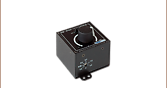
DC4100の背面パネル
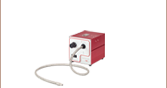
- 1つの外部信号で4つのLEDを一括変調
- 定電流制御ならびに定輝度制御モードによりLEDの電流をそれぞれ設定可能
- LED4Dシリーズ(4波長高出力LED)光源用に設計
- µManager Automation Suiteと互換性あり
LEDドライバDC4100は、4波長LED光源の高出力LEDを0~1000 mAの電流範囲で同時に制御することができます。 LEDの電流は各々に設定するか、背面に位置するBNCポートからの外部信号によって一括して変調することができます(右の写真をご覧ください)。 このドライバは、コネクターハブDC4100-HUBで接続した最大4つまでのファイバ出力型、コリメータ付きならびにコリメータ無しのマウント済みLEDや、コネクターハブDC4100-HUBとケーブルCAB-LEDD1でつないだメタルコアPCB基板実装済みLEDにもお使いいただけます(コネクターハブとケーブルは下記にご用意しております)。
このドライバは前面パネルの回転型セレクタと3つのボタンで操作するか、USB 2.0と付属のソフトウェアパッケージでリモート操作することができます。 詳細については、「概要」および他のタブをご参照ください。

 ズーム
ズーム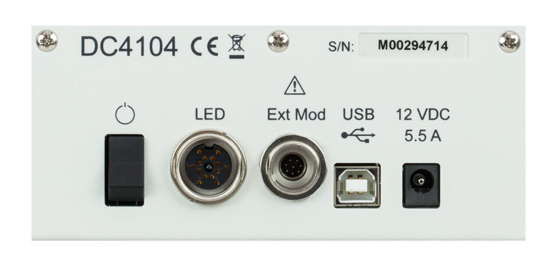
Click to Enlarge
DC4104の背面パネル
Click to Enlarge
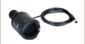
付属の外部変調用ケーブル
- 1本のケーブルから送られる4つの外部信号で、4つのLEDをそれぞれ変調可能
- 定電流制御、定輝度制御、ならびに外部制御モードによりLEDの電流をそれぞれ設定可能
- LED4Dシリーズ(4波長高出力LED)光源用に設計
- µManager Automation Suiteと互換性あり
LEDドライバDC4104は、4波長LED光源の高出力LEDを0~1000 mAの電流範囲で個別に同時制御することができます。 LEDの電流はそれぞれドライバで設定するか、(右の写真の)付属のケーブルから送られる4つの外部信号によりそれぞれ変調することが可能です。ケーブルの追加については当社までお問い合わせください。このドライバは、コネクターハブDC4100-HUBで接続した最大4つまでのファイバ出力型、コリメータ付きまたは コリメータ無しのマウント済みLEDや、コネクターハブDC4100-HUBとケーブルCAB-LEDD1でつないだメタルコアPCB基板実装済みLEDにもお使いいただけます(コネクターハブとケーブルは下記にご用意しております)。構成例については上の図をご覧ください。
このドライバは前面パネルの回転型セレクタと3つのボタンで操作するか、USB 2.0と付属のソフトウェアパッケージでリモート操作することができます。 詳細については、「概要」および他のタブをご参照ください。

 ズーム
ズーム
 ズーム
ズーム  Male M8x1 Connector | Pin | Description | Wire Color |
|---|---|---|---|
| 1 | LED Anode | Brown | |
| 2 | LED Cathode | White | |
| 3 | EEPROM GND | Black | |
| 4 | EEPROM IO | Blue |
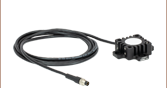
- 一方の端に4ピンのM8コネクタ
- 他方の端に4本の素線
- 長さ2 m、24 AWGワイヤ
4ピンのM8接続ケーブルは、メタルコアPCB基板実装済み高出力LEDやカスタム仕様のLEDを、当社のLEDドライバに接続する際に使用できます。接続可能なLEDドライバは、LEDD1B、DC40、DC2200、DC4100、DC4104(DC4100とDC4104にはDC4100-HUBが必要)です。
ピン接続 - オス
右図では、当社のLEDドライバとお使いいただけるオス型コネクタが掲載されています。このコネクタは、標準品のM8x1丸型センサーコネクタです。ピン1と2はLEDへの接続用です。このケーブルを当社製品以外のLEDにご使用になる場合は、黒と青のワイヤには何も接続しないでください。接続すると、LEDドライバが損傷する場合があります。ここに掲載されているピン配列図は、当社製品以外のLEDドライバにはお使いいただけない場合もありますのでご注意ください。