 Products Home
高出力、マウント付きLED用ドライバー
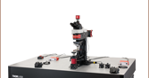
- Driver for Solis® High-Power LEDs for Microscopy
- Supports Thorlabs’ Mounted LEDs
- Internal Modulation Modes Support up to 100 kHz Oscillation
- External Modulation and TTL Input for Integration with
Other Lab Equipment
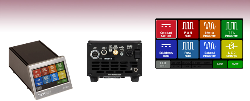
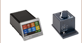
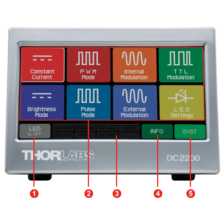
DC2200 Touchscreen Display Main Menu
DC2200
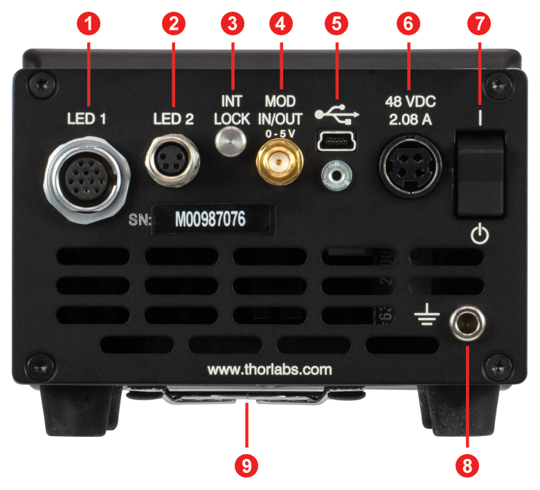
LED DriverBack Panel of the DC2200 Driver


Please Wait
| Key Specifications | |||
|---|---|---|---|
| Item # | DC2200 | ||
| LED Terminal | LED1 | LED2 | |
| LED Current / Max LED Forward Voltagea | 1.0 A / 50.0 V 2.0 A / 35.0 V 4.0 A / 15.0 V 5.0 A / 10.0 V 10.0 A / 5.0 V | 1.5 A / 50.0 V 2.0 A / 35.0 V | |
| LED Current Accuracy | 0.0 - 2.0 A | - | ±(0.1% + 1 mA) |
| 0.0 - 4.0 A | ±(0.1% + 2 mA) | - | |
| 4.0 - 10.0 A | ±(0.1% + 4 mA) | - | |
| LED Current Resolution | 0.1 mA | ||
| Internal Modulation | Waveforms | Sine, Square, Triangle | |
| Frequency Range | 20 Hz to 100 kHz | ||
| External Modulation Small Signal Bandwidthb | DC - 250 kHz | ||
| LED Controller Selection Guide | |||||
|---|---|---|---|---|---|
| Type | Max Number of LEDs | Max Current | Modulation Mode | USB | Compatible LEDs |
| upLED™ LED Driver | 1 | 1.2 A | - | Yes | Mounted Collimated Fiber Coupled Diffuse Backlight PCB Mounteda |
| Compact T-Cube™ Driver | 1 | 1.2 A | 0 - 5 kHz | No | |
| 4-Channel Driver | 4 | 1 A | 0 - 100 kHz | Yes | |
| Solis® LED Driver | 1 | 10 A | 0 - 1 kHz | No | High Power |
| High-Power Touchscreen Driver | 1 | 10.0 A | 0 - 250 kHz | Yes | High Power Mounted Collimated Fiber Coupled Diffuse Backlight PCB Mounteda |
特長
- 当社の多くのLED製品に対応する2種類のLED接続端子を装備
- LED1端子:高出力LEDSolis®用
- LED2端子:マウント済み高出力LED、コリメートLED光源、 ファイバ出力型LED用
- メタルコアPCB基板実装済みLEDは、付属ケーブルCAB-LEDD1Bの使用によりLED2端子に接続できます(詳細は「ピン配列」タブを参照)。
- 駆動モード:定電流モードと輝度モード
- 内部パルスモード
- 調整可能な周波数、デューティサイクル、パルス数
- 正弦波形、矩形波形、三角波形
- 外部トリガならびに変調制御
- EEPROMに保存されたLED情報の読み込み
- USBインターフェイスを介したリモート制御
- 筐体背面のインターロック回路を使用し、お手持ちの非常停止スイッチを取り付け可能
LEDドライバDC2200は、顕微鏡用高出力LED Solisをはじめとする、マウント済みLEDやファイバ出力型LEDなど、当社の多くのLED駆動用に設計されています。ドライバの最大電流は10 A、最大順方向電圧は50 Vです。電流と順方向電圧の組み合わせは右の表をご覧ください。
背面パネルには、2つのLED接続端子が付いていて、当社の高出力ならびにマウント済みLEDすべてが接続可能です。LED1端子は、メス型12ピンNeutrik MiniCONコネクタで、最大10 Aまでの駆動電流が必要な高出力LEDに対応します。LED2端子は、メス型4ピンM8x1コネクタで≤2 Aの駆動電流が必要な低出力LED用に設計されています。この2つの入力端子は上の背面パネルの写真でご覧いただけます。対応するLEDについては下の「Compatible Thorlabs LEDs」の表に記載しています。ドライバには2台のLEDが接続可能ですが、1度に駆動できるのは1台のLEDのみです。2台のLEDを同時に接続している場合、ドライバの前面パネルから駆動電流を供給するLEDを選択することができます。
ドライバは上のスクリーンショットにあるデバイスの前面パネル、またはデバイスの背面にあるUSB 2.0ポートと付属のソフトウェアパッケージを使用してPCから制御することができます( 「ソフトウェア」タブをご参照ください)。前面タッチスクリーンパネルのメインメニューでは、LEDの駆動モードを定電流モードまたは輝度モード、内部または外部パルスモードに選択したり、TTL変調が選択可能です。ドライバは、LEDのEEPROMメモリに保存されたデータを読み込んだ後、LEDの順方向電圧を測定するためのテストシーケンスを開始します。これにより、最大電流リミット値を算出することができます。駆動モードの詳細については「画面表示」タブをご覧ください。
筐体背面には、USB 2.0ポートとLED接続端子のほかにも、外部変調信号用SMA入力端子、お手持ちの非常停止スイッチに接続可能なインターロック回路、そして静電気放電防止製品を使用できる接地用ジャックが付いています。筐体の背面図については「前面&背面パネル」のタブをご覧ください。
DC2200にはカスタム仕様のLEDを接続するための補助ケーブルが2本付いています。1本は、オス型12ピンNeutrik MiniCONコネクタ付きでLED1端子に接続します。もう1本(型番CAB-LEDD1)は、オス型M8x1コネクタ付きでLED2端子に接続します。ケーブルCAB-LEDD1は別途追加でご購入いただくことも可能です(下記参照)。
DC2200の筐体は、112.0 mm x 85.0 mm x 190.3 mmと小型で、4本のゴム脚が付いています。各製品にはAC電源とAC電源ケーブルが付属しています。
| Compatible Thorlabs LEDs | ||||||
|---|---|---|---|---|---|---|
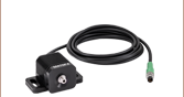
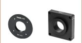
| Photo (Click for Link) |  |  |  | 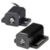 | 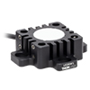 | 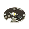 |
| LED Description | High Power | Collimated | Mounted | Fiber Coupled | Diffuse Backlight | PCB Mounteda |
| DC2200 Terminal | LED1 | LED2 | LED2 | LED2 | LED2 | LED2a |
| Specifications | |||
|---|---|---|---|
| LED Terminal | LED1 | LED2 | |
| Constant Current Mode | |||
| LED Current / Max LED Forward Voltage | 1.0 A / 50.0 V 2.0 A / 35.0 V 4.0 A / 15.0 V 5.0 A / 10.0 V 10.0 A / 5.0 V | 1.5 A / 50.0 V 2.0 A / 35.0 V | |
| Setting and Measurement Resolution | 0.1 mA | ||
| Accuracy | Current Range: 0.0 to 2.0 A | - | ±(0.1% + 1 mA) |
| Current Range: 0.0 to 4.0 A | ±(0.1% + 2 mA) | - | |
| Current Range: 4.0 to 10.0 A | ±(0.1% + 4 mA) | - | |
| Noise and Ripple (1 Hz to 10 MHz, RMS, Typical) | Current Range: 0.0 to 2.0 A | - | < 110 µA |
| Current Range: 0.0 to 4.0 A | < 100 µA | - | |
| Current Range: 4.0 to 10.0 A | < 200 µA | - | |
| Current Limit | |||
| Setting Resolution | Current Range: 0.0 to 2.0 A | - | 0.1 mA |
| Current Range: 0.0 to 4.0 A | 0.1 mA | - | |
| Current Range: 4.0 to 10.0 A | 0.1 mA | - | |
| Accuracy | Current Range: 0.0 to 2.0 A | - | ±(0.12% + 1.6 mA) |
| Current Range: 0.0 to 4.0 A | ±(0.12% + 3 mA) | - | |
| Current Range: 4.0 to 10.0 A | ±(0.12% + 6 mA) | - | |
| Measurement | |||
| LED Current Resolution (Display) | 0.1 mA | ||
| LED Current Accuracy | Current Range: 0.0 to 2.0 A | - | ±(0.1% + 1 mA) |
| Current Range: 0.0 to 4.0 A | ±(0.1% + 2 mA) | - | |
| Current Range: 4.0 to 10.0 A | ±(0.1% + 4 mA) | - | |
| LED Voltage Resolutiona | 1 mV | ||
| LED Voltage Accuracya | ±(0.5% + 100 mV) | ||
| PWM (Pulse Width Modulation) Mode | |||
| Frequency | 0.1 Hz to 20 kHz | ||
| Duty Cycle | 0.1% to 99.9% | ||
| Counts | 1 to 1000 or Infinite | ||
| Pulse Mode | |||
| On Time | 1 µs to 10 s | ||
| Off Time | 1 µs to 10 s | ||
| Counts | 1 to 1000 or Infinite | ||
| Internal Modulation Mode | |||
| Waveforms | Sine, Square, Triangle | ||
| Modulation Frequency Range | 20 Hz to 100 kHz | ||
| External Modulation Mode | |||
| Input Impedance | 10 kΩ | ||
| Max Input Voltage | 5.0 V | ||
| Small Signal Bandwidth (Sine)b | DC - 250 kHz | ||
| Modulation Coefficient | Current Range: 0.0 to 2.0 A | - | 400 mA / V |
| Current Range: 0.0 to 4.0 A | 800 mA / V | - | |
| Current Range: 4.0 to 10.0 A | 2000 mA / V | - | |
| TTL Modulation Mode | |||
| Input Impedance | 10 kΩ | ||
| TTL Modulation Bandwidthc | DC to ≥18 kHz | ||
| Low Voltage | 0.0 to 0.8 V | ||
| High Voltage | 2.0 to 5.0 V | ||
| SMA Connector | |||
| External Modulation Input | Input Impedance | 10 kΩ | |
| Max Input Voltage | 5.0 V (Analog) / TTL Level | ||
| Internal Monitor Output | Min Load Impedance | 50 Ω | |
| Output Voltage Level | TTL Level | ||
| General | |||
| Operating Temperature Ranged | 0 to 40 °C | ||
| Storage Temperature Ranged | -40 to 70 °C | ||
| Warm-Up Time for Rated Accuracy | < 10 Minutes | ||
| Dimensions (W x H x D) with Operating Elements | 112.0 mm x 85.0 mm x 190.3 mm (4.41" x 3.35" x 7.49") | ||
| Weight | 0.9 kg | ||
DC2200全面パネル
| Callout | Description |
|---|---|
| 1 | LED On / Off Button |
| 2 | Main Menu |
| 3 | Status Bar |
| 4 | Device Information Button |
| 5 | System Settings Button |
DC2200背面パネル
| Callout | Description |
|---|---|
| 1 | LED1 Terminal for High-Power LEDs |
| 2 | LED2 Terminal for Standard LEDs |
| 3 | Interlock Connector |
| 4 | SMA Connector for External Modulation Input or Monitoring Internal Modulation |
| 5 | USB 2.0 Interface |
| 6 | DC Supply Input |
| 7 | Power-On Switch |
| 8 | Ground Jack |
| 9 | Ventilation Slots |
LEDドライバDC2200のインターフェイスソフトウェアはフラットなメニュー階層構造のため、調整が必要なパラメータを簡単に見つけることができます。下のスクリーンショットは、定電流モード、輝度モード、変調モードなどのドライバの基本機能の例です。
メインメニュー
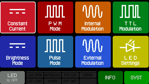
メインメニューにはドライバの基本機能のすべてにリンクするボタンが表示されています。EEPROMデータが内蔵されているLEDの場合、LED設定画面にはメモリに保存されているLEDの情報が表示されます。
LED設定
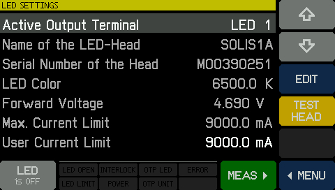
こちらの画面ではLEDのEEPROMメモリに保存されている情報が表示されます。EEPROMメモリが内蔵されていないLEDがドライバに接続している場合、ドライバは自動的にテストを開始してLEDの順方向電圧を測定し、最大電流リミット値を算出します。この場合、LED名とシリアルナンバの欄は「Custom」に、LED Colorの欄は「N/A」と表示されます。User Current Limitは、手動設定のメニューです。
TEST HEADのボタンは、接続されているLEDの動作パラメータを確認するために使用します。ボタンをタップするとドライバがEEPROMメモリを読み込みます。EEPROMがない場合にはテストを開始します。 MEASのボタンを押すと、LEDの電流、電圧、温度(温度センサ付きのLEDの場合)、そしてコンソール温度を含むLEDの測定データが記載されたスクリーンが表示されます(詳細は下記をご覧ください)。
定電流モード
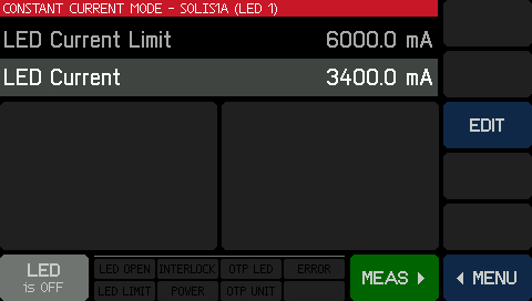
こちらの画面では定電流値でLEDを駆動するための電流設定が可能です。電流リミット値は、LEDのEEPROMメモリに記録されている値以下で、ユーザ設定ができます。値は、EDITのボタン表示をクリックすることにより調整可能です。右のスライドバーが、右の輝度モードのスクリーンショットと同じようにプラス、マイナスそして2本の矢印を表示します。矢印は変更したい数字の位の下にカーソルを移動させるときにご使用ください。プラスとマイナスは、値を変更する際に使用します。DONEを押すことにより変更は保存され、表示は前の画面に戻ります。
LEDにEEPROMが内蔵されておらず、電流リミット値の情報がない場合、LEDの電流リミット値の設定には十分に注意し、適切に調整してください。上記の場合で、お客様による電流リミット値が設定されていない時、ドライバはLEDの順方向電圧を測定し、対応可能な最大駆動電流を算出します。
輝度モード
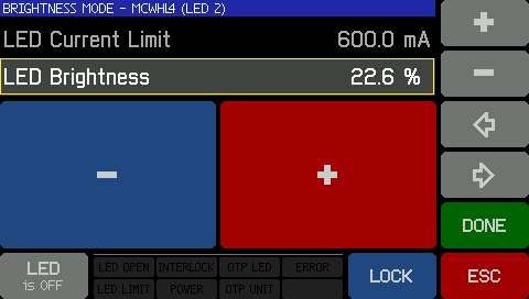
こちらの画面からはLEDの輝度(0~100%)をユーザ設定できます。LEDは定電流で駆動され、輝度は電流リミット値を基準とした割合となります。輝度100%は、LEDのEEPROMメモリに記録されている電流リミット値か、それよりも低いユーザ設定の値に相当します。上のスクリーンショットはLEDの輝度設定が変更される場合に表れる画面です。 右のスライドバーにある矢印は、変更したい数字の位の下にカーソルを移動させるときにご使用ください。プラスとマイナスは、値を変更する際に使用します。DONEを押すことにより変更は保存され、表示は前の画面に戻ります。
LEDにEEPROMが内蔵されておらず、電流リミット値の情報がない場合、LEDの電流リミット値の設定には十分に注意し、適切に調整してください。上記の場合で、お客様による電流リミット値が設定されていない時、ドライバはLEDの順方向電圧を測定し、対応可能な最大駆動電流を算出します。
パルス幅変調(PWM)モード
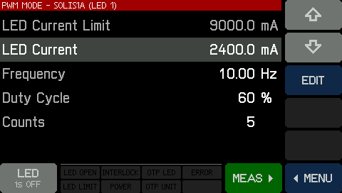
このモードは連続した長方形のパルスを生成し、LEDに供給される電流を変調します。LEDがON時の駆動電流、周波数、デューティーサイクル、そしてパルス数はすべてお客様が選択可能です。矩形パルス時のデューディーサイクルの計算方法についてはこちらのグラフをご参照ください。
パルスモード
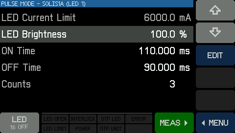
このモードは長方形パルスを使用して駆動電流を変調しますが、LEDパラメータの設定方法は(上記と)異なります。パルス特性は、ユーザ設定のLED輝度、ON時間、OFF時間、そしてパルス数で制御されます。
内部変調モード

こちらのモードは、LEDを単にON/OFFに切り替える以上の要件が必要な用途向けで、正弦、矩形、三角波形でLED電流を変調します。LEDの最小と最大両方の電流が設定できます。このモードでは20 Hz~100 kHzの変調周波数に対応します。
外部変調モード

さらに複雑な用途向けには、外部変調信号を背面パネルのSMAコネクタを介してドライバに入力することができます。ドライバは0~5 Vの入力に対応します。この端子は、フルスケール電流の20%を超えない正弦波変調、最大250 kHzのLED電流変調に対応します。ほかの波形も使用できますが、最大変調周波数は下がります。
TTL変調モード
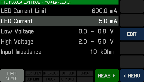
このモードでは、単純なLEDのON/OFF変調をほかの機器からの信号(DC2200の背面パネルにあるSMAコネクタを介して入力)により行うことができます。TTL信号が「High」のとき供給されるLED Currentはユーザ設定が可能です。Low Voltage、High Voltage、Input Impedanceは参照するために表示されていますが、変更はできません。
システム設定
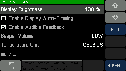
システム設定メニューへは、メインメニュー右下の緑色のSYSTボタンをクリックしてください。設定メニューでは、ディスプレイや音量設定を調整したり、使用ユニットを設定したり、ファームウェアの更新を行うことができます(「ソフトウェア」タブ参照)。LED Safety Modeは、LEDがONの時、LEDの操作パネルがほかの画面に切り替わらないよう防止します。このスクリーンでEnableもしくはDisableに設定可能です。
DC2200 ピン配列
LED1端子
12ピン Neutrik MiniCON メス型コネクタ
| Pin | Connection | Pin | Connection |
|---|---|---|---|
| 1 | LED Cathode | 7 | LED Anode |
| 2 | LED Cathode | 8 | LED Cathode |
| 3 | Not Used | 9 | LED Cathode |
| 4 | LED Anode | 10 | Not Used |
| 5 | LED Anode | 11 | EEPROM (Data) I/O |
| 6 | LED Anode | 12 | EEPROM (Data) Ground |
LED2端子
M8x1 メス型コネクタ
| Pin | Description |
|---|---|
| 1 | LED Anode |
| 2 | LED Cathode |
| 3 | EEPROM GND |
| 4 | EEPROM I/O |
外部トリガ
SMA メス型
0~5 V、0~250 kHz外部変調
(詳細は「仕様」タブをご覧ください)
コンピュータ接続
USB Mini-B*

*USB A型-Mini-Bコネクタ変換ケーブルが付属します。
LED1端子用補助ケーブル
最大10 Aの電流で駆動されるカスタム仕様の高出力LEDは、DC2200に付属するケーブルCAB-DC2200を使用してLED1端子に接続することができます。ケーブルをカスタム仕様のLEDにつなぐときには、LEDのカソードととケーブルの4本のカソードをすべて接続し、アノードも同様に接続します。それにより、ドライバがサポートする最大電流10.0 Aまで引き出すことができます。
補助ケーブルピン配列
12ピンNeutrik MiniCONオス型コネクタ
| Pin | Wire Color | Description |
|---|---|---|
| 1 | Green | LED Cathode |
| 2 | Yellow | LED Cathode |
| 3 | Gray | 6 V - 13 V for Fan Power Supply |
| 4 | Orange | LED Anode |
| 5 | Blue | LED Anode |
| 6 | Red | LED Anode |
| 7 | Black | LED Anode |
| 8 | White | LED Cathode |
| 9 | Brown | LED Cathode |
| 10 | Violet | Ground for Fan Power Supply |
| 11 | White and Black Striped | DO NOT CONNECT |
| 12 | White and Brown Striped | DO NOT CONNECT |
LED2端子用補助ケーブル
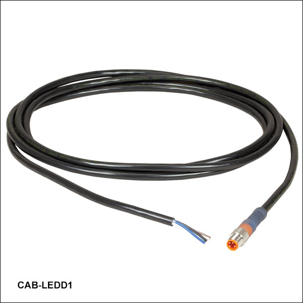
最大2 Aの電流で駆動されるカスタム仕様LEDは、ケーブルCAB-LEDD1Bを使用してLED2端子に接続することができます。
ケーブルCAB-LEDD1のピン配列
M8x1 オス型コネクタ
| Pin | Wire Color | Description |
|---|---|---|
| 1 | Brown | LED Anode |
| 2 | White | LED Cathode |
| 3 | Black | DO NOT CONNECT |
| 4 | Blue | DO NOT CONNECT |
注:黒と青色のワイヤには何も接続しないでください。LEDドライバDC2200に損傷を与える可能性があります。
ドライバDC2200用ソフトウェア
下記のリンクをクリックするとソフトウェアをダウンロードいただけます。
ソフトウェア
ソフトウェア バージョン 1.7 (2022年6月21日)
ファームウェア バージョン 1.4.2 (2022年6月21日)
DC2200用GUIソフトウェア、ファームウェア、ファームウェアアップグレードウィザードのダウンロード。
DC2200のパッケージには以下の製品が含まれます。
- LED電流コントローラDC2200
- 電源
- カスタム仕様のLEDをLED1端子に接続するためのケーブル
- カスタム仕様LEDをLED2端子に接続するためのケーブル(型番CAB-LEDD1)
- USB 2.0ケーブル
- SMA-BNCケーブルCA2806
- クイックスタートマニュアル
| LED Terminal | LED1 | LED2 |
|---|---|---|
| LED Current / Max LED Forward Voltagea | 1.0 A / 50.0 V 2.0 A / 35.0 V 4.0 A / 15.0 V 5.0 A / 10.0 V 10.0 A / 5.0 V | 1.5 A / 50.0 V 2.0 A / 35.0 V |
LEDの適用可否を決定するLED電流と最大順方向電圧
LEDドライバは電流源です。つまり、駆動されているドライバの規定の順方向電圧でユーザ設定の電流を供給します。これらのドライバには、最大電流のほかに最大電圧が設定されているため、LEDに使用するドライバを決めるうえで両方を考慮しなければなりません。
DC2200は、LED1端子に接続されたLEDについては5種類の電流範囲の中から1つ、LED2端子に接続されたLEDについては2種類の中から1つの電流範囲で使用できます。この電流範囲の制限により、LEDを駆動する順方向電圧が最大にしています。予め設定された電流範囲とその最大順方向電圧については右表をご覧ください。LEDの適用可否を決定するうえで、LED Current/Max LED Forward Voltageは以下のように解釈します。
- 1.0 A / 50.0 V:1.0 A未満の電流で駆動されているLEDの順方向電圧は50.0 V以下でなければならない。
- 2.0 A / 35.0 V:1.0 A以上2.0 A未満の電流で駆動されているLEDの順方向電圧は35.0 V以下でなければならない。
- 4.0 V / 15.0 V:2.0 A以上4.0 A未満の電流で駆動されているLEDの順方向電圧は15.0 V以下でなければならない。
よって、LEDの適用可否は、駆動電流値より大きい中で最小のLED電流値を選択し、LEDの最大順方向電圧値と比較することによって決定します。順方向電圧が駆動電流の最大電圧よりも小さいLEDは使用可能です。
例1.適用可能なLED: LED1端子に接続可能なコネクタ付きで、駆動電流8 A、順方向電圧4.8 VのLEDの場合、ドライバDC2200の定格電流10.0 Aを使用します。この時、DC2200で相当する最大順方向電圧は5.0 Vです。よって、駆動電流8 A、順方向電圧4.8 VのLEDは使用可能です。
例2.適用できないLED: LED1端子に接続可能なコネクタ付きで、駆動電流4.2 A、順方向電圧11 VのLEDの場合、ドライバDC2200の定格電流5.0 Aを使用します。この時、DC2200の最大順方向電圧は10.0 Vです。よって、駆動電流4.2 A、順方向電圧11 VのLEDは使用可能です。
ドライバの設計:電流・順方向電圧仕様の設定
実際、最大順方向電圧はドライバの供給電流量に反比例します。電流値が高くなるとドライバの最大順方向電圧値は低くなります。電流・順方向電圧の組み合わせが設定されたのは、ドライバが電流範囲の上限値において、最低でも規定の順方向電圧に対応できるようにするためです。 下の3つのグラフは、ドライバDC2200の最大電圧の実測値の例です。LED1端子で2 A、4 A、10 Aの3種類の電流範囲で測定されました。実際の性能はドライバによって変動がありますが、上記仕様の範囲内となります。
Click to Enlarge
0~2 Aの電流範囲で設定されたDC2200の供給電流と最大順方向電圧の関係性。このグラフは例示を目的とするものです。性能はユニット毎に異なる(ただし、仕様の範囲内)ため、LEDの適用可否を決定するためにご使用にならないでください。

Click to Enlarge
0~4 Aの電流範囲で設定されたDC2200の供給電流と最大順方向電圧の関係性。このグラフは例示を目的とするものです。性能はユニット毎に異なる(ただし、仕様の範囲内)ため、LEDの適用可否を決定するためにご使用にならないでください。
Click to Enlarge
0~10 Aの電流範囲で設定されたDC2200の供給電流と最大順方向電圧の関係性。このグラフは例示を目的とするものです。性能はユニット毎に異なる(ただし、仕様の範囲内)ため、LEDの適用可否を決定するためにご使用にならないでください。
| Posted Comments: | |
Maxime ALEXANDRE
(posted 2023-10-22 19:57:14.857) Hello,
1/ Does the DC2200 is compatible with M3400L1 - 3400 nm, 2.2 mW (Min) Mounted LED, 200 mA ?
If yes:
2/ I want to use DC2200 to generate a single pulse of about 100 µs with a delay of about 100 µs using an external trigger TTL signal.
3/ I also want to use DC2200 to generate a pulse frequency of 1 kHZ and use the internal TTL as a reference signal for a lock-in amplifier. Is it possible?
Thank for your help
Maxime dpossin
(posted 2023-10-24 09:07:18.0) Dear Maxime,
Thank you for your feedback. The proposed components are compatible together and also the suggested pulse pattern can be achieved by the DC2200 driver. The internal modulation can be used in order to trigger a third party device via the mod in/out port in the figure of an TTL signal. I am reaching out to you to further discuss your question. dpossin
(posted 2023-10-24 09:07:18.0) Dear Maxime,
Thank you for your feedback. The proposed components are compatible together and also the suggested pulse pattern can be achieved by the DC2200 driver. The internal modulation can be used in order to trigger a third party device via the mod in/out port in the figure of an TTL signal. I am reaching out to you to further discuss your question. Wenhong Yang
(posted 2022-03-24 15:40:23.56) Hello, recently we bought the DC2200 to modulate the LED. But the maximum modulation time is only 10000 ms. We need at least 10 min. Would you please help me to change this parameter? Thanks a lot. Wenhong Yang
(posted 2022-03-22 19:25:38.253) Hello, recently we bought the DC2200 to modulate the LED. But the maximum modulation time is only 10000 ms. We need at least 10 min. Would you please help me to change this parameter? Thanks a lot. Julian K.
(posted 2021-03-31 03:09:48.047) Hello,
can I use the DC2000 to drive Laser Diodes as well?
Best
Julian wskopalik
(posted 2021-04-01 10:15:44.0) Thank you for your inquiry!
The DC2200 is a DC current source similar to usual laser diode drivers. Laser diode drivers usually have less noise on the current, especially those designed for lower current levels. But theoretically the DC2200 can also be used to drive laser diodes.
The DC2200 is however designed for the operation of LEDs and therefore might not have all the necessary laser safety features to comply with the regulations in your country. Therefore I would definitely recommend to get the approval of the laser safety officer in your facility before using it to drive laser diodes.
I will also contact you directly to provide further assistance. maxime babics
(posted 2020-12-14 12:52:21.573) We are using the DC2200 with the M880L3 LED for a publication. What are the rise and decay time of the LED when using the pulse mode?
thank you MKiess
(posted 2020-12-15 07:46:36.0) Thank you very much for your inquiry. Generally, the rise and fall time is in the µs range for this controller. However, it always depends on the settings used, the modulation mode and the current. I have contacted you directly to discuss further details. Selimen BENAHMED
(posted 2020-10-13 15:12:21.837) Hello
I got a DC2200 power supply loaned.
I want to test it for my application.
I connect an output load of 8.7 ohm and check that I can generate 1A on my loads (pulse mode or PWm mode). My problem is that the max forward voltage is reached for a current value lower than 300mA. Is there a procedure to allow this Limit voltage to be changed (forward Voltage).
I studied your manuals but it is not explained I searched in the different parameters of the current driver and I did not find anything
Kind regards MKiess
(posted 2020-10-15 10:49:28.0) Dear Selimen, thank you very much for your inquiry. I have contacted you directly to discuss the details with you. Simon Walker
(posted 2020-09-29 05:06:06.127) Can the DC2200 operate so that it receives a 5V ttl pulse (from an attached high-speed camera), but the duration of the output pulse to the LED is independent from the duration of the input ttl pulse.
In my case, I want the camera to have a long exposure (1/frame rate) while running at ~4kHz, but for the LED to only turn on for 5us in each exposure.
Looking at the manual online, it appears this functionality isn't available but I wanted to check.
Thanks MKiess
(posted 2020-09-29 09:52:35.0) Dear Simon, thank you very much for your inquiry. When the DC2200 is operated in TTL modulation mode, it works with standard TTL level signals.
This means that for TTL high level the LED is on and for TTL low level the LED is off. So it is not possible to control the LED independent of the TTL pulse by using the modulation input with a TTL signal.
In order to discuss the possibilities to realize this with the DC2200 and your camera, I contacted you directly. Luis Baute
(posted 2020-04-07 10:02:40.94) DC2200 when used in PWM mode, it feedbacks with an error, would you mind helping solve this please
Thanks nreusch
(posted 2020-04-07 11:17:08.0) This is a response from Nicola at Thorlabs. The additional information you provided via email indicate that this is most likely a software issue. I will contact you directly to discuss possible solutions. Lee Aspitarte
(posted 2019-12-09 21:00:04.45) Hi, I am attempting to switch a M590F3 LED with a DC2200 driver with a TTL signal. I am noticing that there is a decay of the LED brightness when switching on the order of a few milliseconds. i.e. I still register a small signal when acquiring with my spectrometer (for 5 ms) a few ms after sending the TTL low signal, while the following acquisition ~10ms is totally dark. I am switching between 0 and 12 mA.
This does not make sense to me with the cited modulation rates of ~100kHz which I take to mean the LED should be off ~10 microseconds after the TTL low pulse. It's possible that what is going on is something else within my setup but I want to confirm that the LED turning off ~10us after the off TTL pulse is the expected behavior. Is there anything I can do with the DC2200 to make the LED turn off faster? I notice that the 'dark' state of the LED in TTL mode corresponds to ~1V forward bias, which I assume is to reduce the turn on time. dpossin
(posted 2019-12-12 08:29:35.0) Hello Lee
Thank you for your feedback. In TTL mode the modulation frequency of the DC2200 is limited to 18kHz which corresponds to ~ 0.05ms. The instrument is only able to provide modulation frequencies up to 100kHz for analog modulation. The Low and High TTL level can be adjusted in the TTL Modulation Mode menu of the DC2200 (see in the manual page 19 for further information). The maximum possible modulation frequency also depends on the fall and rise time of the diode itself and can be even lower than 18kHz. Paul Alvarez
(posted 2019-07-24 21:07:51.853) Recently bought DC2200 and installed the software as mentioned but the remote connection is not working. MKiess
(posted 2019-07-29 08:31:01.0) This is a response from Michael at Thorlabs. Thank you for your inquiry. You seem to have the same issue as described in Tommy Ringuette's feedback. I have contacted you directly for further assistance. Bruno Bernardo Alfonso
(posted 2019-07-15 16:24:41.81) Just wanted to write because of a bug that is probably in the newest driver version. I have bought the dc2200 driver and installed the newest software version and when I try to connect it to my computer and click to the "Connect" green button, TMC-ID starts flashing and it doesn't connect. I talked to one of your agents and told me it is a bug and you are already working on it.
Hope it works soon! Please, I really need the software!
Thanks a lot! MKiess
(posted 2019-07-29 08:38:37.0) This is a response from Michael at Thorlabs. Thank you so much for contacting Thorlabs. If the LED is not connected or not connected correctly, the device will not be switched to the remote state. Please check the LED connection at the controller. I contacted you directly to continue our discussion. Tommy Ringuette
(posted 2019-07-03 11:31:50.497) Hi,
I updated the firmware of our DC2200 to 1.2.0 and the remote control stop working. When I try to connect, the screen the button “local” flash once and then TMC-ID flash a few times. MKiess
(posted 2019-07-09 05:08:13.0) This is a response from Michael at Thorlabs. Thank you for your inquiry. When the DC2200 is in remote mode, some additional information appears in the status bar of the display. The information LOCAL appears, when the LOCAL button was pressed during the remote operation. The unit is then operable locally but returns to remote mode with the first received remote command. TMC-ID flashes a few times when a remote identification request is received. After receiving the first remote command, the device is set to the remote state. Jim Jacob
(posted 2019-03-16 17:00:18.943) I ordered a DC2200 a few weeks ago. When it works, it is great for my application. The problem is that the touch screen is intermittent. The unit comes up in the Int Mod mode, and is difficult to switch out to another mode. The touch screen seems to have a problem. nreusch
(posted 2019-03-22 09:48:50.0) This is a response from Nicola at Thorlabs. Thank you for reporting this issue. I will contact you directly for further assistance. jimjacob
(posted 2019-02-09 19:04:13.22) Can the DC2200 be externally triggered to provide pulsed light pulses? I want to generate a 20 microsecond long pulse on demand, at a pule rate up to 30Hz. nreusch
(posted 2019-02-15 10:45:03.0) This is a response from Nicola at Thorlabs. Thank you for your inquiry. Yes, you can trigger DC2200 externally by using the external trigger SMA input. The bandwidth of this port is DC to 250 kHz, so you will be able to use it at rates of 30 Hz. hiqoqo
(posted 2018-01-22 17:04:14.56) Dear
I am reading the manual to buy DC2200 and I want to know how to operate TTL and external modulation. I don't understand their principle. In manual, there have not detailed information. Please give me the detail information of TTL and external modulation. Thank you. swick
(posted 2018-01-26 05:48:02.0) This is a response from Sebastian at Thorlabs. Thank you for the inquiry.
With external modulation it is possible to modulate the signal in triangle, sinusoidal and further waveforms.
In TTL modulation mode only rectangular shaped pulses are possible.
I contacted you directly for further assistance. massimo
(posted 2017-07-26 16:00:43.17) Is it possible to find information about operating this unit in Linux with the NI-VISA back-end and PyVISA? I'm using CentOS 7 with NI-VISA 17.0 for Linux, but PyVISA seems to say that no instrument has been found on the USB.
I've been able to correctly communicate with the DC2200 with PyVISA in Windows10, with installed NI-VISA 17.0 for Windows, but thus far I couldn't do the same in CentOS.
Any hint would be really useful. wskopalik
(posted 2017-07-27 10:22:07.0) This is a response from Wolfgang at Thorlabs. Thank you very much for your inquiry.
Unfortunately, we have no experience with operating the DC2200 on a Linux system. The software as well as the drivers are only available for Windows. Your approach however sounds promising. Basically you could use the NI-VISA interface to build up a connection to the DC2200. Then you could send SCPI commands to the DC2200 and control it that way.
I will contact you directly to discuss the issues you have with PyVISA in more detail. charmlee
(posted 2017-05-25 17:41:27.36) Could I use external trig to turn on/off Pulse mode?
ie. When TTL high, DC2200 continue output Pulse (1 us on follow by 5 us off) and when TTL low, DC2200 stop output. swick
(posted 2017-05-30 03:06:25.0) This is a response from Sebastian at Thorlabs. Thank you for the inquiry.
At DC2200 the SMA connector (MOD IN/OUT) at the rear panel accepts TTL signals but TTL Low Level corresponds to LED OFF and TTL High Level to LED ON. I will contact you directly to provide further assistance. raphael
(posted 2017-04-10 09:21:36.587) Hello. Does the DC2200 show ripples in the LED drive current?
Thanks swick
(posted 2017-04-18 04:02:55.0) This is a response from Sebastian at Thorlabs. Thank you for the inquiry.
For DC2200 the Noise and Ripple (1 Hz to 10 MHz, RMS, Typical) is specified with
Current Range: 0.0 to 2.0 A<110 µA (LED2 Terminal)
Current Range: 0.0 to 4.0 A<100 µA (LED1 Terminal)
Current Range: 4.0 to 10.0 A<200 µA (LED1 Terminal) user
(posted 2016-10-28 12:53:26.977) Can I use the DC2200 to drive non-Thorlabs LEDs? swick
(posted 2016-10-31 04:08:54.0) This is a response from Sebastian at Thorlabs. Thank you very much for your inquiry.
Yes, it is possible to drive non-Thorlabs LEDs with DC2200.
Each DC2200 includes two auxiliary cables for connecting custom LEDs to the driver. One cable has a male 12-pin Neutrik MiniCON connector that is compatible with the LED1 terminal. The second cable (Item # CAB-LEDD1) has a male connector compatible with the LED2 terminal. reynolds.gw.2
(posted 2016-09-30 07:58:02.04) Can you supply me the command set for integrating this LED driver into custom software?
Thanks,
Geoff swick
(posted 2016-09-30 08:29:03.0) This is a response from Sebastian at Thorlabs. Thank you very much for your inquiry. You can find information on how to write your own application for DC2200 in the manual at page 37 and following.
I have contacted you directly for providing assistance. bruce
(posted 2016-09-20 12:56:30.61) Hi,
I'd like to ask for the Trigger Latency. I want to drive the SMA modulation input connector with a TTL signal, and I'd like to know how long it will take, following a rising edge on the TTL input, for a ThorLabs M470L3-C5 LED source to reach full output illumination.
Please reply by email.
Thank you,
Bruce swick
(posted 2016-09-22 03:22:43.0) This is a response from Sebastian at Thorlabs. Thank you very much for your inquiry. I will contact you directly to provide requested information. avinashiiser1042
(posted 2015-11-16 11:22:06.227) Hi,
I am a graduate student at Simon Fraser University. We are planning to buy an LED source for illumination for one of our projects. We want an LED source that should flash with really short exposure (~ 100 KHz). I found DC2200 very interesting and relevant. Can we operate it at around 100 KHz with pulse width around 1 microsecond?
Avinash Kumar shallwig
(posted 2015-11-17 04:13:36.0) This is a response from Stefan at Thorlabs. Thank you very much for your inquiry. Depending on the needed waveform 100 kHz might be out of the specifications the driver has. If you need for example square pulses the cutoff frequency for sharp square signals lies at about 20 kHz as stated for the PWM mode in the spesc:http://www.thorlabs.com/newgrouppage9.cfm?objectgroup_id=9117&pn=DC2200#9171
The modulation capabilities may also be limited by the LED you want to modulate. I will contact you directly to check which LED at which current and waveform you need to modulate and we will check if the DC2200 can fulfill your needs. |
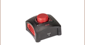
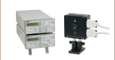
当社ではSolis® LED駆動用に2種類のドライバをご用意しております。DC20はベーシックなモデルで、LEDの発光強度は上部のコントロールノブと、変調用の外部TTL信号入力端子を用いて制御します。より高度な用途向けのドライバDC2200では、タッチパネル式のインターフェイスからLED電流の制御、内部または外部変調モードの選択ほか、様々な操作ができます。下表では主なコントローラの特長の比較がご覧いただけます。
| Solis® LED Driver Selection Guide | ||
|---|---|---|
| Item # | DC20 | DC2200 |
| Photo (Click to Enlarge) | 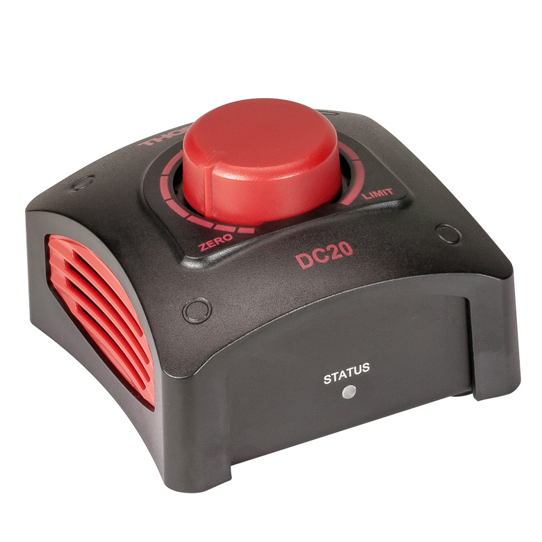 |  |
| LED Current / Forward Voltage (Max) | 1 to 10 A / 5.0 to 14.0 Va | 1.0 A / 50.0 Vb 2.0 A / 35.0 Vb 4.0 A / 15.0 Vb 5.0 A / 10.0 Vb 10.0 A / 5.0 Vb |
| Noise and Ripple (1 Hz to 10 MHz, RMS, Typical) | <400 µA | <100 µA from 0.0 to 4.0 A <200 µA from 4.0 to 10.0 A |
| Internal Modulation Modes | - | 0.1 Hz to 20 kHz (PWMc Mode) 1 µs to 10 s On or Off Time (Pulse Mode) 20 Hz to 100 kHz (Internal Modulation Mode with Sine, Square, Triangle Waveforms) |
| External Modulation (Arbitrary Waveform) | - | DC - 250 kHz [Small Signal Bandwidth (Sine)]d |
| TTL Modulation (External) | DC to 1 kHz (Square Wave, PWMc) | DC to ≥18 kHze |
| LED Control Interface | Knob to Control LED Current, BNC Port for TTL Modulation | Easy-to-Navigate Touchscreen Interface, Brightness and Constant Current Operating Modes, Internal and External Modulation Modes, SMA Port for External Modulation Accepts TTL Signal or Waveform from a Function Generator, USB Interface for Remote Control |
| Current Limit | Automatically Read and Set from the Solis LED's Internal Memory to Protect the LED from Overdriving | |
| External Software Interface | No | DC2200 GUI |
| Other Compatible LEDs | - | Mounted Collimated Fiber Coupled MCPCB Mountedf |

 ズーム
ズーム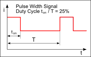
 Male M8x1 Connector | Pin | Description | Wire Color |
|---|---|---|---|
| 1 | LED Anode | Brown | |
| 2 | LED Cathode | White | |
| 3 | EEPROM GND | Black | |
| 4 | EEPROM IO | Blue |
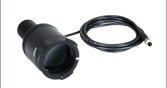
- 一方の端に4ピンのM8コネクタ
- 他方の端に4本の素線
- 長さ2 m、24 AWGワイヤ
4ピンのM8接続ケーブルは、メタルコアPCB基板実装済み高出力LEDやカスタム仕様のLEDを、当社のLEDドライバに接続する際に使用できます。接続可能なLEDドライバは、LEDD1B、DC2200、DC4100、DC4104(DC4100とDC4104にはDC4100-HUBが必要)です。
ピン接続 - オス
右図では、当社のLEDドライバとお使いいただけるオス型コネクタが掲載されています。このコネクタは、標準品のM8x1丸型センサーコネクタです。ピン1と2はLEDへの接続用です。ここに掲載されているピン配列図は、当社製品以外のLEDドライバにはお使いいただけない場合もありますのでご注意ください。