 Products Home
精密キネマティックミラーマウント
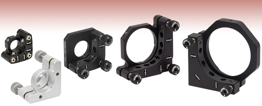
- Ø1/2", Ø1", Ø2", Ø3", & Ø4" Mounts Available
- High-Precision Differential Adjusters Available
KS05
Ø1/2" Mirror Mount
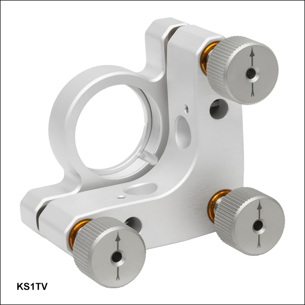
KS1TV
Ø1" Vacuum-Compatible Mirror Mount
KS1T
Internally SM1-Threaded Ø1" Mirror Mount
KS2D
High-Resolution
Ø2" Differential
Adjuster Mirror Mount
KS3
Ø3" Mirror Mount


Please Wait
真空対応部品
当社の多くのオプトメカニクス部品は真空の用途向けに特注が可能です。詳細については当社までお問い合わせください。
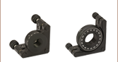
特長
- 当社の2アジャスタ型キネマティックミラーマウントに比べて、厚みのある背面プレートと強力バネで安定性が向上
- Ø12.7 mm~101.6mmの光学素子用キネマティックマウント
- ±4°のあおり調整(ピッチ&ヨー)
- ロック可能なアジャスタ
- Ø25 mm~Ø25.4 mm、Ø50 mm~Ø50.8 mm光学素子用の差動アジャスタ付きモデル
- Ø12 mm~Ø12.7 mm、Ø25 mm~Ø25.4 mm、Ø50 mm~Ø50.8 mm光学素子用はSMネジ付きバージョンあり
- Ø25 mm~Ø25.4 mm光学素子用のSM1ネジ付き真空対応モデル
- 90º配置の取付け穴により右手系、左手系どちらの構成も可能
- 中心をずらした取付けオプションもあり(KS05/M、KS05K/M、KS05T/M、KS1、KS1Tは除く)
こちらの精密キネマティックミラーマウントは頑丈な機械設計により、長期安定性に優れています。当社の標準的な2アジャスタ型キネマティックミラーマウントに比べ、3アジャスタ型マウントは、厚い背面プレートと強力なバネで作られています。真空対応キネマティックマウントKS1TVを除くすべてのマウントでは、固定可能なアジャスタがドリフトを低減し、長期安定性を確保します。真空対応キネマティックマウントのアジャスタを固定するには、別売りの止めナットPOLARIS-LN1を取り付ける必要があります。こちらのページでご紹介しているすべてのマウントは、±4°の調整角を有しています。
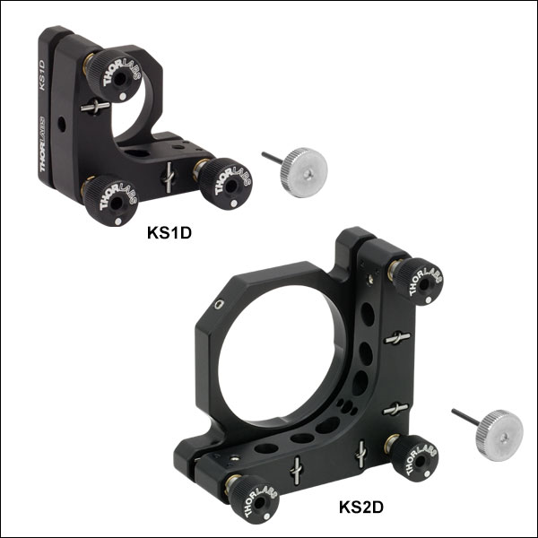
3アジャスタ型マウントには、標準アジャスタまたは作動アジャスタが付いています。標準アジャスタのネジはマウントのサイズに合わせて、3/16"-100、1/4"-80または1/4"-100となっており、ステンレススチール製のボールチップが付いています。Ø25 mm~Ø25.4 mm(1インチ)光学素子用キネマティックミラーマウントKS1DおよびØ50 mm~Ø50.8 mm(Ø2インチ)光学素子用キネマティックミラーマウントKS2Dは、あおり調整(ピッチ&ヨー)部分に差動アジャスタが適用されており、精密な角度調整ができます。KS1D、KS2Dでは、最小角度変化量はそれぞれ2.91 μrad、1.45 μradです(詳細については下記をご参照ください)。
こちらのマウントでは、先端がナイロン製の止めネジにより側面で光学素子を保持する製品と、SMネジにより固定リングで光学素子を保持する製品の2種類があります。SMネジ付きのマウントには、当社のレンズチューブを取り付けることができます。
当社では様々な種類の2アジャスタ、3アジャスタ型ミラーマウントをご用意しております。さらに安定性が高いPolaris®ミラーマウントもございます。
| Item # | Optic Diameter | Minimum Optic Thickness | Optical Axis Height | Angular Adjustment | Number of Adjusters | Type of Adjusters | Adjuster Thread | Resolutiona | Clear Apertureb | Mounting |
|---|---|---|---|---|---|---|---|---|---|---|
| KS05(/M) | 1/2" or 12.0 mm | 0.12" (3.0 mm) | 0.58" (14.7 mm) | ±4º | 3 | Hex Socket | 3/16"-100 | 12.8 mrad/rev | Ø0.47" (Ø11.9 mm) | 8-32 (M4) Tapped Holes, 2 Places |
| KS05K(/M) | 1/2" or 12.0 mm | 0.12" (3.0 mm) | 0.58" (14.7 mm) | ±4º | 3 | Removable Knobs | 3/16"-100 | 12.8 mrad/rev | Ø0.47" (Ø11.9 mm) | 8-32 (M4) Tapped Holes, 2 Places |
| KS05T(/M)c | 1/2" or 12.0 mm | 0.16"d (4.1 mm) | 0.58" (14.7 mm) | ±4º | 3 | Hex Socket | 3/16"-100 | 12.8 mrad/rev | Ø0.44" (Ø11.2 mm) | 8-32 (M4) Tapped Holes, 2 Places |
| KS1 | 1" or 25.0 mm | 0.16" (4.1 mm) | 1.0" (25.4 mm) | ±4º | 3 | Removable Knobs | 1/4"-80 | 7.4 mrad/rev | Ø0.94" (Ø23.9 mm) | #8 (M4) Counterbored Holes, 2 Places |
| KS1Tc | 1" or 25.0 mm | 0.14"d (3.6 mm) | 1.0" (25.4 mm) | ±4º | 3 | Removable Knobs | 1/4"-80 | 7.4 mrad/rev | Ø0.90" (Ø22.9 mm) | #8 (M4) Counterbored Holes, 2 Places |
| KS1TV | 1" or 25.0 mm | 0.28"d (7.11 mm) | 1.0" (25.4 mm) | ±4º | 3 | Removable Knobs | 1/4"-100 | 9.3 mrad/rev | Ø0.90" (Ø22.9 mm) | #8 (M4) Counterbored Holes, 2 Places |
| KS2 | 2" or 50.0 mm | 0.20" (5.1 mm) | 1.56" (39.6 mm) | ±4º | 3 | Removable Knobs | 1/4"-80 | 4.8 mrad/rev | Ø1.94" (Ø49.3 mm) | #8 (M4) Counterbored Holes, 6 Places |
| KS2Tc | 2" or 50.0 mm | 0.10"d (2.5 mm) | 1.81" (46.0 mm) | ±4º | 3 | Removable Knobs | 1/4"-80 | 4.8 mrad/rev | Ø1.90" (Ø48.3 mm) | #8 (M4) Counterbored Holes, 6 Places |
| KS3 | 3" or 75.0 mm | 0.28" (7.1 mm) | 2.13" (54.1 mm) | ±4º | 2 | Removable Knobs | 1/4"-80 | 5.0 mrad/rev | Ø2.82" (Ø71.6 mm) | #8 (M4) Counterbored Holes, 4 Places |
| KS4 | 4" | 0.28" (7.1 mm) | 2.85" (72.4 mm) | ±4º | 2 | Removable Knobs | 1/4"-80 | 3.9 mrad/rev | Ø3.94" (Ø100.1 mm) | #8 (M4) Counterbored Holes, 4 Places |
| KS1D | 1" or 25.0 mm | 0.16" (4.1 mm) | 1.0" (25.4 mm) | ±4º | 3 | Removable Knobs | 1/4"-80 / M3 x 0.40 / M3 x 0.375e | 660 μrad/rev | Ø0.94" (Ø23.9 mm) | #8 (M4) Counterbored Holes, 2 Places |
| KS2D | 2" or 50.0 mm | 0.20" (5.1 mm) | 1.56" (39.6 mm) | ±4º | 3 | Removable Knobs | 1/4"-80 / M3 x 0.40 / M3 x 0.375e | 400 μrad/rev | Ø1.94" (Ø49.3 mm) | #8 (M4) Counterbored Holes, 6 Places |
Click to Enlarge
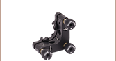
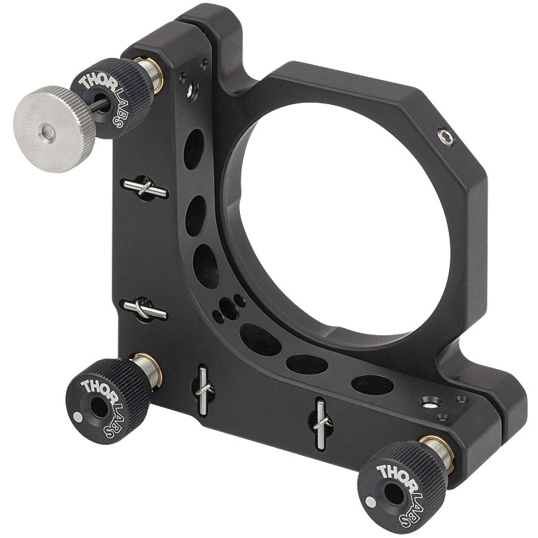
Figure 3.1 付属の六角レンチが付いたØ50 mm~Ø50.8 mm(Ø2インチ)差動アジャスターミラーマウントKS2D。差動アジャスタの微調整は付属の六角レンチで、粗調整はこの写真の黒色アルミニウム製ノブで行います。
差動アジャスタ
KS1DおよびKS2Dは、2つの差動アジャスタと1つの標準アジャスタを搭載しています。 差動アジャスタは付属の取外し可能な六角レンチで微調整できます。また、黒色のアルミニウム製ノブを使って粗調整することも可能です。 KS1DとKS2Dの両製品ともに、標準アジャスタを使用した際の角度調整範囲は±4°です。差動アジャスタのみを使用した時の角度調整範囲については、KS1Dは±1.5° 、KS2Dは ±0.9°です。
KS1DおよびKS2Dは、2つの差動アジャスタDAS110を使用して、318 μm の粗調整および 25 μm の微調整が可能です(KS1DおよびKS2Dには固定リングは付属していません)。 差動の機構はFigure 3.2でご覧ください。
粗調整
Figure 3.2にあるように、ノブ「A」は1/4"-80外ネジ付きの本体「B」に固定されており、Figure 3.2のキネマティックマウントの角度の粗調整ができます。 このノブを取り外して5/64インチ六角ソケットを露出させ、粗調整することも可能です。粗調整アジャスタ(1/4"-80ネジ付き本体)は、本体に3/16"-100ネジが付いているKS05/MとKS05K/M以外のすべての精密マウントでは標準仕様です。
Click for Details
Figure 3.2 差動アジャスタ機構の概略図
微調整
本体「B」には M3内ネジが付いています。 このネジは内部にアクチュエータ「C」が保持されており、六角レンチで回転させることができます。中間アクチュエータが内ネジと外ネジの両方を備えているので、部品「C」とプッシュロッド「D」の間で差動を行なうことができます。
「C」の外ネジは、本体内側のM3ネジと同じサイズです。 中間アクチュエータが時計回りに回転すると、1 回転につき400 μmずつ本体から移動します。 M3ネジで「C」の内ネジに接続されたプッシュロッド「D」は、本体「B」により回転が妨げられます。「C」が回転すると400 μm/revの速度で前進します。一方、プッシュロッドは375 μm/revで後退します。この結果、1 回転につきプッシュロッドは、2つのネジの正味ピッチ差に等しい25 μm/rev の差動変異を生じます。
| Posted Comments: | |
Andreas Baum
(posted 2024-03-20 12:47:24.707) Dear Thorlabs,
is there a stepper motor compatible with the KS4 mirror mount? We would like to motorize our setup with the option for reproducible scanning of the mirror, which neither piezos nor piezo inertia actuators can provide due to their drift and loss of steps.
Best
Andreas jdelia
(posted 2024-03-29 10:55:03.0) Thank you for contacting Thorlabs. Our actuators, including stepper motors, can be found here: https://www.thorlabs.com/navigation.cfm?guide_id=83. The KS4 adjusters have 1/4"-80 threads so you would need the actuator to match the thread type. I have reached out to you directly to discuss your application. Tamara Delgado
(posted 2023-10-23 13:27:29.22) Have you got any kinematic mount for 1" optics with adjusters than can be independently locked (excluding the kinematic mount for 30 mm cage)?
Thank you!!! cdolbashian
(posted 2023-10-27 03:45:49.0) Thank you for reaching out to us with this inquiry! Since the knobs on the actuators (the black ones) are removable, any adjuster can be made to be lockable by using a locking nut on the actuator. The 1" mount, KS1, has 1/4"-80 actuators, and as such, you could use 3x of these locking nuts to secure each of the 3 axis: LN2580. Kenneth Maxwell
(posted 2023-08-24 10:59:09.33) Please add adapter plates to fit 2" and 3" optics in this mount. Or provide a new design.
Using a beam splitter in a standard mirror mount, causes clipping on the back side of the optic. Either on the adjustment knobs, or the back plate the knobs are mounted to. This is a common issue for mounting large beam splitters. Need a solution for 2 to 4 inch diameter beam splitters. cdolbashian
(posted 2023-08-30 10:24:20.0) Thank you for your suggestion here! After discussing this with you, I understand your difficulties. If your intent is to use a beamsplitter plate from all directions, the kinematic-adjuster mechanism partially obscures one of the 4 transmission/reflection directions, whereas the other 3 would nominally be unaffected. A potential solution would be a B4C kinematic platform, where all of the kinematic control is in the base of the unit, and you would be free to place a fixed, minimally-obscuring, optic mount on the top of such a platform. This way you would have all the rotational kinematic control without additional obscuration. I have contacted you directly to discuss this in more detail. Charles Moher
(posted 2023-05-21 17:05:11.25) I have one of these but the corner adjuster is a graduated micrometer type barrel. Why does Thor not label it's products with model numbers ? cdolbashian
(posted 2023-05-26 12:33:57.0) After contacting you, it seems like you have an old revision of one of our 2" precision kinematic mirror mounts, and an unidentified optic. Over 95% of our products do indeed have an engraved part number on the body of each respective component. We apologize for the inconvenience in this case. user
(posted 2022-02-23 01:29:07.737) What's the tolerance on the minimal optical thickness that each mount can accept?
How feasible is it to use the KS3 (3") precision kinematic mount (which is stated to only accept a minimal optical thickness of 7.1mm) - to accommodate a 3" round plate that is 6mm thick? Thanks cdolbashian
(posted 2022-02-24 04:49:38.0) Thank you for reaching out to us regarding the minimum mountable optic thickness for our mirror mounts. Due to the mounting method the optic must be at least the specced thickness in order for the optic to both, mount flush with the back surface of the housing, and be fully contacted with the nylon-tipped setscrew. Timo Junker
(posted 2020-12-22 00:48:15.44) Hello,
how is the Beam Deviation After Thermal Cycling of KS05/M and KS1D compared to the Polaris Mounts?
Thank you vwery much
Timo Junker llamb
(posted 2020-12-23 03:09:59.0) Hi Timo, thank you for contacting Thorlabs. Generally, our aluminum mounts are designed for general purpose applications at room temperature, so they will not perform nearly as well as the Polaris mounts in terms of Beam Deviation after thermal cycling. While not explicit to the KS05/M or KS1D, I will reach out to you directly with some data we have comparing Polaris mounts to our aluminum mounts. Dimitar Slavov
(posted 2020-10-06 09:51:52.263) Dear colleagues,
May I have from you a copy of the KS2 solid works file for Solid Works 2013 or older version. In difference to the files for other mounts that I have downloaded from your pages, that one can not be opened by my software.
Thank you in advance llamb
(posted 2020-10-09 08:14:44.0) Thank you for contacting Thorlabs. As SolidWorks does not allow saving files as previous versions, I would instead recommend trying the KS2's Step File, which will not have the same version restrictions that the pure SolidWorks file may have. I have reached out to you directly as well. abc124771
(posted 2018-12-12 04:07:56.877) Can KS3 be available in 1"? I basically require 2 or 3 adjuster kinematic mounts which can be brought as close to each other as possible. The regular KM100 mounts have small projections on the front plate which prevents two such plates to be brought too close together. Which mounts would you suggest for my purpose? Also the aperture of the mounts has to be clear from the back since I need transmission too. YLohia
(posted 2018-12-12 12:41:21.0) The 1" version of the KS3 is already available on this page with the part number KS1. For transmission and close proximity of two plates, we recommend looking into the KS1CE. andy.violette
(posted 2017-11-13 12:03:47.33) Is it required to mount the KS1D to 3 surfaces, rather than just 2 (where the mounting bolts are), for precision, thanks nbayconich
(posted 2017-12-20 10:13:41.0) Thank you for contacting Thorlabs. We have found that using 2 mounting surfaces is sufficient for most applications. If ultra precision is of concern we would recommend the polaris series of mounts which include dowel holes for alignment. I will reach out to you directly about your application. user
(posted 2016-07-21 16:32:26.083) On the `How it Works' tab, in the second sentence under `Coarse Adjustment', it is written `5/64" kex socket' instead of hex socket. nicolas.perlot
(posted 2015-12-18 23:33:50.27) Does KS1 (resp. KS2) differ from KS1D (resp. KS2D) only by the adjusters?
If I have a KS1 and a KS1D, can I interchange the adjusters? And can I use motorized actuators such as Z812 on both KS1 and KS1D? Thanks. jlow
(posted 2015-12-21 04:57:07.0) Response from Jeremy at Thorlabs: The only difference between the two would be the adjusters. The adjusters can be taken off and replaced with other actuators that has 1/4"-80 thread, such as the Z812. mcmasterbm
(posted 2014-10-20 08:15:47.98) Please tell me what the standard lubricant is? I need a low outgassing PTFE based lubricant rather than a petroleum lube.
I'd also like a clear anodize version.
Please tell me what I would need to order this option.
Thanks. jlow
(posted 2014-10-22 04:14:17.0) Response from Jeremy at Thorlabs: The grease we typically use for these is a mixture of Apiezon M and Nye PG-44A grease. We can quote these with other type of grease and clear anodization as well. I will contact you directly for the quote. You can also contact us at techsupport@thorlabs.com for quotes in the future. user
(posted 2014-01-07 12:05:55.273) I would like to know the pitch of the thread of a KS4 mirror mount. You've stated the thread type but this thread can be fine or superfine, having different pitch... jlow
(posted 2014-01-07 08:28:56.0) Response from Jeremy at Thorlabs: The KS4 uses 1/4"-80 adjusters so the screw pitch would be 1/80 of an inch (0.3175mm). hambitza
(posted 2013-06-26 14:05:38.307) I know that the resolution of a mirror mount is usually determined by the pitch size of the screw. However, I am asking myself in which steps I can actually turn the screw. For example, could I turn the screw by 5 or 10 degree by hand? For me the final resolution would be determined by the fine adjustment steps in which I can change the mirror angle. cdaly
(posted 2013-07-02 11:02:00.0) Response from Chris at Thorlabs: Thank you for using our feedback tool. This is somewhat subjective to the ability of the user, but with a simple hex key rather than a ball driver, it should be possible to get somewhere in the range of 2-6 degrees of revolution of the lead screws pretty reliably. bdada
(posted 2012-02-13 15:19:00.0) Response from Buki at Thorlabs:
Thank you for your valuable feedback on the KS1 and KM100 families. I have brought up your idea of a standard mounting screw with our design engineers. We do not have your contact information, so please email TechSupport@thorlabs to discuss this matter further. user
(posted 2012-02-11 16:26:01.0) I mix different mirror mounts in the KS1 and KM100 families, the mounting screw has a different length for each family, would you consider making one standard. Murphy's law comes into play here as i always have the wrong screw. bdada
(posted 2011-11-07 14:10:00.0) Response from Buki at Thorlabs:
Thank you for participating in our Feedback Forum. The Polaris is designed to provide the ultimate in thermal stability so we expect it to perform better than our Ultra Stable Kinematic Mirror Mounts. We will run some tests to compare the performance of the Polaris to these mounts. Please contact TechSupport@thorlabs.com if you have further questions. user
(posted 2011-11-05 00:52:46.0) Can you do thermal testing on these mounts so I can compare to the Polaris. I think they might be just as good but not sure. jpang
(posted 2007-12-19 10:34:48.0) It would be helpful to have all maximum angular range listed for all your kinematic mirror mounts. |
光学素子用精密キネマティックミラーマウント")
 ズーム
ズーム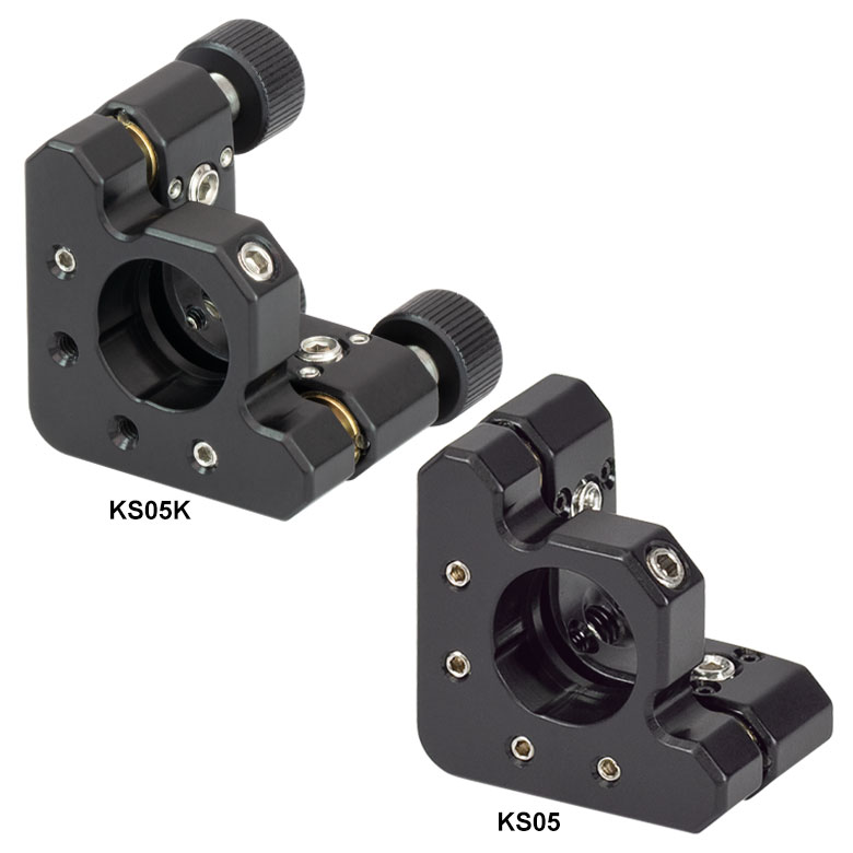
Click to Enlarge
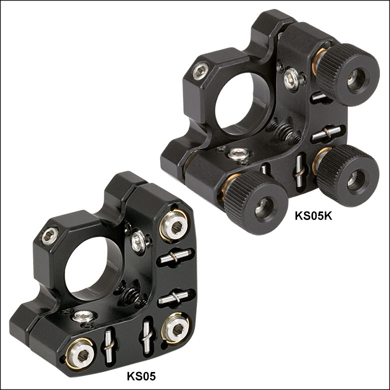
Figure G1.1 精密ミラーマウントKS05(/M)ならびにKS05K(/M)の前面
- 先端がナイロン製の止めネジ(セットスクリュ)付き2重穴で光学素子を固定
- 厚みのある背面プレートと強力バネにより安定性が改善
- 黒色アルマイト加工
- キネマティック接触点に使用されている硬化ステンレスが摩耗を低減
- ノブ付き、無しの両方をご用意
こちらの精密キネマティックミラーマウントは、Ø12 mm~Ø12.7 mm(Ø1/2インチ)の光学素子用に設計されており、取り外し可能なノブ付きタイプとノブ無しタイプをご用意しております。いずれも±4°のあおり調整(ピッチ&ヨー)が可能です。 当社の2アジャスタ型ミラーマウントと比べて背面プレートに厚みがあるので安定性に優れています。マウント質量の増加に加え、全ての接触面に剛性の強化されたバネと硬化インサートが組み込まれているので、全体的な性能が向上しています。
各マウントに付いている3/16"-100 TPIの3つのアジャスタでミラーマウントの前面プレートを移動させることにより、±4°のあおり調整が可能です。 対称な調整幅(つまり±4°)を得るためには、前面と背面プレートの間の間隔は1.65 mmでなければなりません。 3つのアジャスタを全て使用した場合、Z方向への線形移動は、KS05/Mでは6.35 mm、KS05K/Mでは4.57 mmとなります。マウントにはM4タップ穴が2つ付いており、左手系、右手系のどちらの向きにもポスト取付けが可能です。
KS05/MとKS05K/Mどちらにも3/16"-100の固定可能なアジャスタが3つ付いています。 KS05/Mのアジャスタの長さは12.7 mm、KS05K/Mは19.1 mmです。 KS05/Mは六角レンチで調整するので、多くのØ12 mm~Ø12.7 mmの光学素子マウントが設置しにくい狭い場所でも設置が可能です。 一方、KS05K/Mには取り外し可能な3/16"-100の黒色アルミニウム製のノブが付いていて、ボール(六角)ドライバや六角レンチ類が使用できないようなスペースの制限されたセットアップにも設置できます。マウントKS05K/Mはアジャスタに長期的な安定性が求められる場合や、セットアップが衝撃や振動にさらされる場合は、ノブを取り外してアジャスタを止めナットLN19100またはLN19100Hでロックすることも可能です。
| Item # | Optic Diameter | Minimum Optic Thickness | Optical Axis Height | Angular Adjustment | Number of Adjusters | Type of Adjustersa | Adjuster Thread | Clear Aperture | Mounting |
|---|---|---|---|---|---|---|---|---|---|
| KS05(/M) | 1/2" or 12.0 mm | 0.12" (3.0 mm) | 0.58" (14.7 mm) | ±4º | 3 | Hex Socket | 3/16"-100 | Ø0.47" (Ø11.9 mm) | 8-32 (M4) Tapped Holes, 2 Places |
| KS05K(/M) | 1/2" or 12.0 mm | 0.12" (3.0 mm) | 0.58" (14.7 mm) | ±4º | 3 | Removable Knobs | 3/16"-100 | Ø0.47" (Ø11.9 mm) | 8-32 (M4) Tapped Holes, 2 Places |
光学素子用精密キネマティックミラーマウント、SM05ネジ付き")
 ズーム
ズーム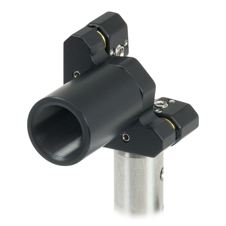
Click to Enlarge
Figure G2.2 KS05T(/M)内にねじ込まれたØ12 mm~Ø12.7 mm(Ø1/2インチ)レンズチューブ
Click to Enlarge
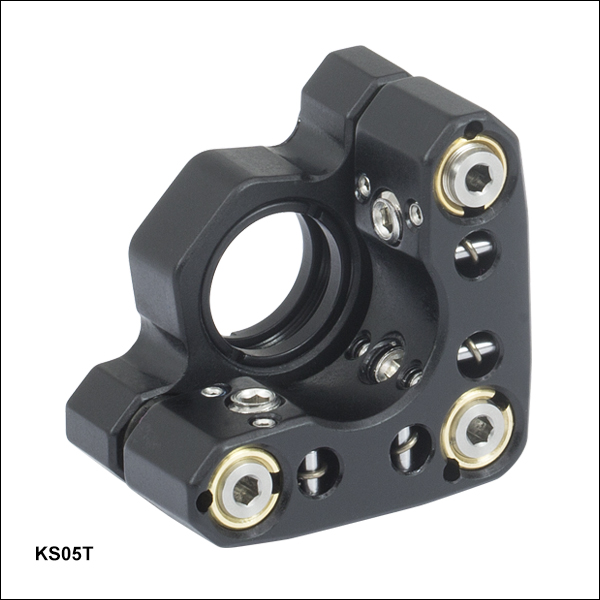
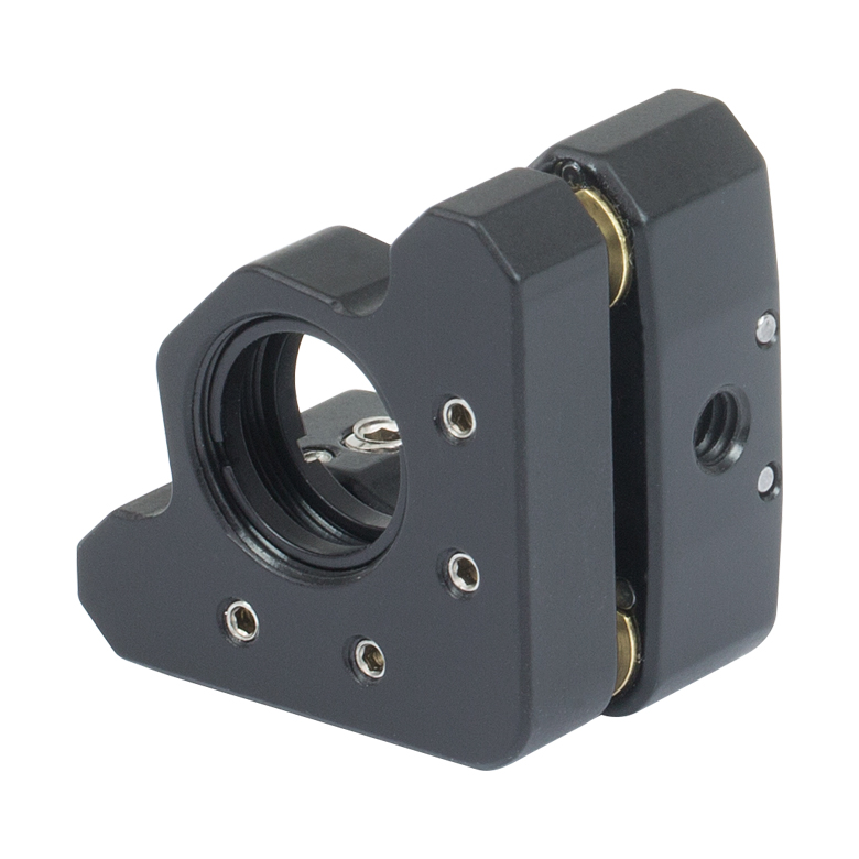
Figure G2.1 SM05ネジ付きミラーマウントKS05T(/M)の前面
- SM05内ネジ付きの光学セルがØ12 mm~Ø12.7 mm(Ø1/2インチ)レンズチューブに対応
- 付属の固定リングでØ12 mm~Ø12.7 mm(Ø1/2インチ)の薄型光学素子を保持
- M4タップ穴により右手および左手方向に取付け可能
- 厚みのある背面プレートと強力バネにより安定性が改善
- 黒色アルマイト加工
- キネマティック接触点に使用されている硬化ステンレスが摩耗を低減
ネジ付き精密キネマティックミラーマウントKS05T/Mは、Ø12 mm~Ø12.7 mm(Ø1/2インチ)の光学素子用で、±4°のあおり調整(ピッチ&ヨー)ができます。付属の2個の固定リングSM05RRで低応力の取付けが可能です。光学素子はスパナレンチSPW603を使用して固定できます。 真ちゅうのブッシュが付いたステンレススチール製のアジャスターネジがスムーズな調整を行います。
2アジャスタ型ミラーマウントと比べて背面プレートに厚みがあるので安定性に優れています。また、マウント質量の大きさに加え、全ての接触面に剛性の強化されたバネと硬化インサートが組み込まれているので、全体的な性能も向上しています。SM05内ネジ付きの光学セルは、Ø12 mm~Ø12.7 mm(Ø1/2インチ)レンズチューブに対応しています(Figure G2.2参照)。
各マウントに付いている固定可能な3つの3/16"-100 TPIアジャスタでミラーマウントの前面プレートを移動させることにより、±4°のあおり調整が可能です。 対称な調整幅(つまり±4°)を得るためには、前面と背面プレートの間の間隔は1.65 mmでなければなりません。3つのアジャスタ全てを動かすと、Z方向へ6.35 mmのリニア移動が可能です。
| Item # | Optic Diameter | Maximum Optic Thickness | Optical Axis Height | Angular Adjustment | Number of Adjusters | Type of Adjustersa | Adjuster Thread | Clear Aperture | Mounting |
|---|---|---|---|---|---|---|---|---|---|
| KS05T(/M) | 1/2" or 12.0 mm | 0.16" (4.1 mm) | 0.58" (14.7 mm) | ±4º | 3 | Hex Socket | 3/16"-100 | Ø0.44" (Ø11.2 mm) | 8-32 (M4) Tapped Holes, 2 Places |
、Ø50 mm~Ø50.8 mm(Ø2インチ)光学素子用精密キネマティックミラーマウント")
 ズーム
ズーム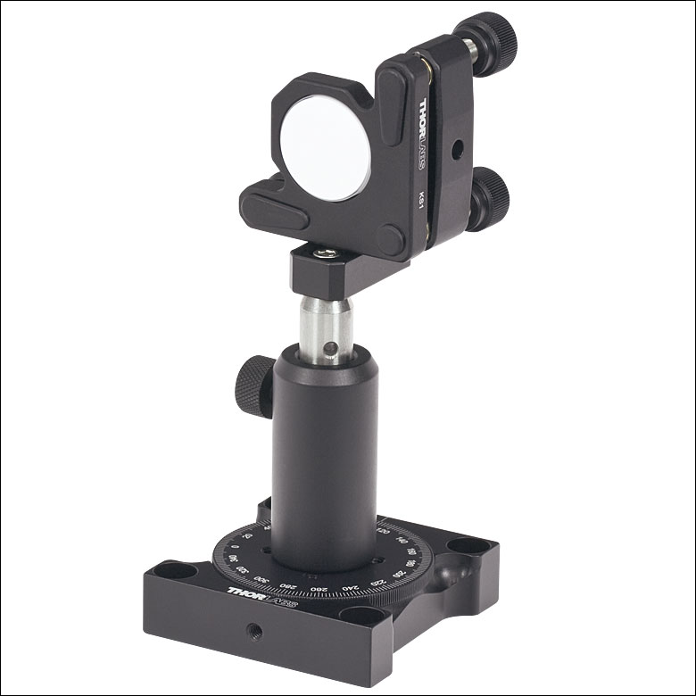
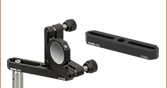
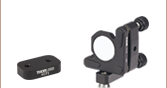
Click to EnlargeFigure G3.2 キネマティックマウントKS1に取り付けられたミラーは、可変式センタリングプレートKMCP(/M)によってポスト回転軸上に配置することができます。
Click to Enlarge
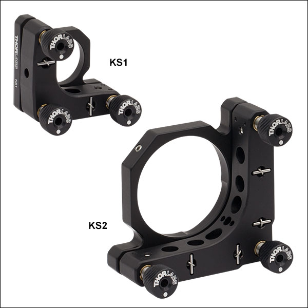
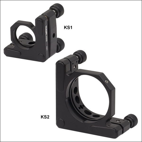
Figure G3.1 KS1およびKS2の前面
- 先端がナイロン製の止めネジ(セットスクリュ)付き2重穴で光学素子を固定
- 厚みのある背面プレートと強力バネにより安定性が改善
- 黒色アルマイト加工
- キネマティック接触点に使用されている硬化ステンレスが摩耗を低減
精密キネマティックマウントKS1はØ25 mm~Ø25.4 mm(Ø1インチ)の光学素子、KS2はØ50 mm~Ø50.8 mm(Ø2インチ)の光学素子を保持する設計で、±4°のあおり調整(ピッチ&ヨー)が可能です。また、先端がナイロン製の止めネジにより、光学素子を傷つけずに保持することができます。アジャスタは固定ネジでロックすることができますが、内蔵されているプリテンションスクリュを先に締めた状態で 微調整を行い、その後、固定ネジでロックすることにより、ロックした際のビームのシフトを最小限に抑えることができます。 真ちゅうのブッシュが付いたステンレススチール製の送りネジがスムーズな調整を行います。 ザグリ穴により左手系、右手系のどちらの向きにもポストの取付け可能です。
2アジャスタ型ミラーマウントと比べて背面プレートに厚みがあるので安定性に優れています。マウント質量の増加に加え、全ての接触面に剛性の強化されたバネと硬化インサートが組み込まれているので、全体的な性能も向上しています。
1/4"-80 TPIの3つの固定可能なアジャスタでミラーマウントの前面プレートを移動させることにより、±4°のあおり調整が可能です。 対称な調整幅(つまり±4°)を得るためには、前面と背面プレートの間の間隔はKS1では3.05 mm、KS2では4.83 mmでなければなりません。 3つのアジャスタを全て使用した場合、Ø25 mm~Ø25.4 mm(Ø1インチ)ならびにØ50 mm~Ø50.8 mm(Ø2インチ)光学素子用キネマティックミラーマウントはZ方向に最大6.4 mm移動します。
| Item # | Optic Diameter | Minimum Optic Thickness | Optical Axis Height | Angular Adjustment | Number of Adjusters | Type of Adjustersa | Adjuster Thread | Mounting |
|---|---|---|---|---|---|---|---|---|
| KS1 | 1" or 25.0 mm | 0.16" (4.1 mm) | 1.0" (25.4 mm) | ±4º | 3 | Removable Knobs | 1/4"-80 | #8 (M4) Counterbored Holes, 2 Places |
| KS2 | 2" or 50.0 mm | 0.20" (5.1 mm) | 1.56" (39.6 mm) | ±4º | 3 | Removable Knobs | 1/4"-80 | #8 (M4) Counterbored Holes, 6 Places |
、Ø50 mm~Ø50.8 mm(Ø2インチ)光学素子用精密キネマティックミラーマウント、SMネジ付き")
 ズーム
ズーム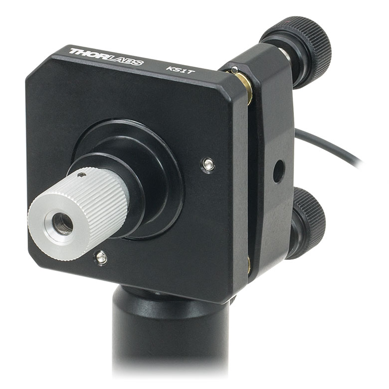
Click to Enlarge
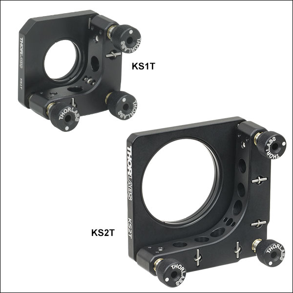
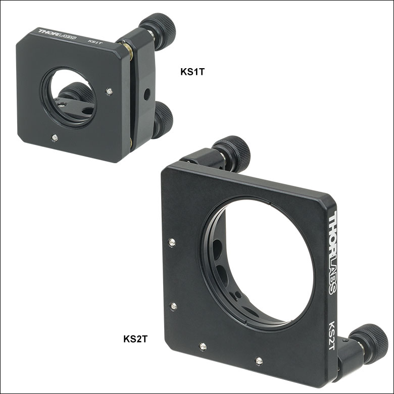
Figure G4.1 KS1TとKS2Tの前面
- SM1またはSM2内ネジによりレンズチューブに対応
- 付属の固定リングでØ25 mm~Ø25.4 mm(Ø1インチ)またはØ50 mm~Ø50.8 mm(Ø2インチ)の薄型光学素子を保持
- M4ザグリ穴(貫通穴)で、右手系または左手系での取り付けが可能
- 厚みのある背面プレートと強力なバネにより安定性が改善
- 黒色アルマイト加工
- キネマティック接触点に使用されている硬化ステンレスが摩耗を低減
ネジ付き精密キネマティックミラーマウントKS1TおよびKS2Tには、それぞれØ25 mm~Ø25.4 mm(Ø1インチ)、Ø50 mm~Ø50.8 mm(Ø2インチ)の薄型光学素子を取り付けられ、±4°のあおり調整(ピッチ&ヨー)ができます。2個の固定リングSM1RR(KS1T)またはSM2RR(KS2T)を用いて小さなストレスでの取付けが可能です。固定リングSM1RRの取付けにはスパナレンチSPW606、SM2RRの取付けにはSPW604が使用できます。 真ちゅうのブッシュが付いたステンレススチール製の送りネジによりスムーズな調整が行えます。ザグリ穴により左手系、右手系のどちらの向きにもポストの取付けが可能です。
2つのアジャスタ付きミラーマウントと比べて、背面プレートに厚みがあるので安定性に優れています。マウント質量の増加に加え、全ての接触面に剛性の強化されたバネと硬化インサートが組み込まれているので、全体的な性能も向上しています。KS1TにはSM1内ネジが付いており、Ø25 mm~Ø25.4 mm(Ø1インチ)レンズチューブが取り付けられます。また、KS2TにはSM2内ネジが付いており、Ø50 mm~Ø50.8 mm(Ø2インチ)レンズチューブが取り付けられます。Figure G4.2のように、これらの内ネジはネジ付きアダプタにも対応しているため、半導体レーザーモジュールやファイバーコリメータなど様々な部品を取り付けることができます。
各マウントには固定可能な3つの1/4"-80 TPIアジャスタがついており、ミラーマウントの前面プレートを移動させることにより±4°のあおり調整が可能です。対称な調整幅(つまり±4°)を得るためには、前面と背面プレートの間の間隔はKS1では3.05 mm、KS2では4.83 mmでなければなりません。3つのアジャスタを全て使用した場合、Ø25 mm~Ø25.4 mm(Ø1インチ)およびØ50 mm~Ø50.8 mm(Ø2インチ)キネマティックミラーマウントはZ方向に最大6.4 mm移動します。
| Item # | Optic Diameter | Maximum Optic Thickness | Internal Threading | Optical Axis Height | Angular Adjustment | Number of Adjusters | Type of Adjustersa | Adjuster Thread | Mounting |
|---|---|---|---|---|---|---|---|---|---|
| KS1T | 1" or 25.0 mm | 0.14" (3.6 mm) | SM1 (1.035"-40) | 1.0" (25.4 mm) | ±4º | 3 | Removable Knobs | 1/4"-80 | #8 (M4) Counterbored Holes, 2 Places |
| KS2T | 2" or 50.0 mm | 0.10" (2.5 mm) | SM2 (2.035"-40) | 1.81" (46.0 mm) | ±4º | 3 | Removable Knobs | 1/4"-80 | #8 (M4) Counterbored Holes, 6 Places |
光学素子用キネマティックミラーマウント、SMネジ付き")
 ズーム
ズーム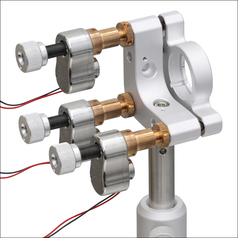 Click to Enlarge
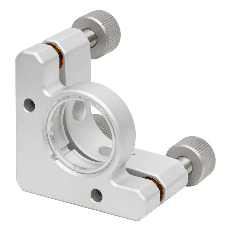 Click to Enlarge
Figure G5.1 正面
- 光学セルはSM1内ネジ付き
- 付属の固定リングを使用して厚さ7.1 mmまでのØ25 mm~Ø25.4 mm(Ø1インチ)光学素子を取り付け可能
- M4ザグリ穴(貫通穴)で、右手系または左手系での取り付けが可能
- パッケージから取り出した状態で10-6 Torrまでの真空で使用可能
真空対応キネマティックミラーマウントKS1TVは、厚さ7.1 mmまでのØ25 mm~Ø25.4 mm(Ø1インチ)光学素子に対応し、±4ºのあおり調整(ピッチ&ヨー)が可能です。光学素子は付属の真空対応固定リングを用いて固定可能です。固定リングを取り付ける際はスパナレンチSPW606をご使用いただけます。リン青銅のブッシュとステンレススチール製の送りネジによりスムーズな調整が行えます。M4ザグリ穴により、左手系、右手系のどちらの向きにもポストが取り付けられます。
2アジャスタ型ミラーマウントと比べて、背面プレートに厚みがあるので安定性に優れています。マウント質量の増加に加え、剛性の強化されたバネと全ての接触点に硬化インサートが使用されているので、全体的な性能も向上しています。KS1TVにはSM1内ネジ付きの光学セルが付いています。
こちらのマウントには固定可能な3つの1/4"-100 TPIアジャスタがついており、ミラーマウントの前面プレートを移動させることにより±4ºのあおり調整が可能です。対称な調整幅(つまり±4°)を得るためには、前面と背面プレートの間の間隔を3.05 mmとする必要があります。3つのアジャスタを全て使用した場合、このマウントはZ方向に最大6.4 mm移動します。アジャスタを固定するには、別売りの止めナットPOLARIS-LN1を取り付ける必要があります。各アジャスタを取り外して、Figure G5.2のように真空対応ピエゾ慣性アクチュエータPIAK10VF を代わりに取り付けることができます。これにより0.5 µradの分解能(典型値)での角度調整が可能となります。
真空対応
当社の真空対応マウントは、梱包前に化学洗浄され、真空での用途向けに処理されています。10-6 Torrまでの真空状態では、袋から取り出してそのままお使いいただけます。追加洗浄や加工によりさらに高い真空度での使用も可能です。ただし、部品からのアウトガスにより限界があります。マウント本体の6061-T6アルミニウムは、使用されている中で最もアウトガスが高い材料です。マウントと材質が具体的な真空システムにおいて適切かどうかは、その材質特性とお客様が行った洗浄方法によりご判断ください。
| Item # | Optic Diameter | Maximum Optic Thickness | Optical Axis Height | Angular Adjustment | Number of Adjusters | Type of Adjustersa | Adjuster Thread | Clear Aperture | Mounting |
|---|---|---|---|---|---|---|---|---|---|
| KS1TV | 1" or 25.0 mm | 0.28" (7.11 mm) | 1.00" (25.4 mm) | ±4º | 3 | Removable Knobs | 1/4"-100 | Ø0.90" (Ø22.9 mm) | #8 (M4) Counterbored Holes, 2 Places |
、Ø50 mm~Ø50.8 mm(Ø2インチ)光学素子用キネマティックミラーマウント、差動アジャスタ")
 ズーム
ズームClick to Enlarge
Figure G6.2 六角ネジがついたØ50 mm~Ø50.8 mm(Ø2インチ)光学素子用マウントKS2D
Click for Details
Figure G6.1 差動アジャスタ機構の概略図。差動アジャスタ機構の内部動作の詳細は、上部の「操作方法」タブをご参照ください。
- ナイロン製の止めネジ(セットスクリュ)付き2重穴に光学素子を固定
- 厚みのある後部プレートと強力バネにより安定性が改善
- 黒色アルマイト加工
- キネマティック接触点に使用されている硬化ステンレスが摩耗を低減
このØ25 mm~Ø25.4 mm(Ø1インチ)とØ50 mm~Ø50.8 mm(Ø2インチ)光学素子用キネマティックミラーマウントは、固定用差動アジャスタと安定性の高いマウント部によって、 2アジャスタ型キネマティックミラーマウントに比べて長期的な安定性が得られる製品です。キネマティックミラーマウントKS1DにはØ25 mm~Ø25.4 mm、KS2DにはØ50 mm~Ø50.8 mmの光学素子がそれぞれ保持できます。ミラーマウントの前後部プレートの間隔が、KS1Dでは3.05 mm、KS2Dでは4.83 mmの場合、角度調整幅は±4度です。このアジャスタは、3つのアジャスタすべてを使用する場合、Z軸方向に最大6.4 mmの移動が可能です。
マウントについているアジャスタ3つのうち2つには、差動機構が組み込まれています(詳細は、「操作方法」 タブ参照)。この超高分解能ドライブシステムは、粗調整(318 µm/回転、Figure G6.1のB)と微調整(25 µm/回転、Figure G6.1のCとD)の両方が可能です。微調整ドライブシステムには2本の親ネジを使います。1本は中心スピンドルを1回転につき400 µm前進させ、もう1本は1回転につき375 µm後退させます。その結果、中心スピンドルの正味前進移動量は1回転につき25 µmとなり、これは、KS1Dの場合では1回転660 µrad、KS2Dの場合では1回転400 µradに相当します。差動機構を作動させるには、六角レンチを粗調整ノブ(Figure G6.1のA)に通し、調整ネジに内蔵されている中間アクチュエータを回します。
| Item # | Optic Diameter | Minimum Optic Thickness | Coarse Angular Adjustment | Adjuster Thread | Coarse Resolutiona | Resolution Using Differential Mechanisma | Minimum Incremental Movementb | Mounting Style | Angular Range with Differential Mechanism | Pitch and Yaw Differential Adjuster |
|---|---|---|---|---|---|---|---|---|---|---|
| KS1D | 1" or 25.0 mm | 0.16" (4.1 mm) | ±4º | 1/4"-80 / M3 x 0.40 / M3 x 0.375d | 8.3 mrad/rev | 660 µrad/rev (136 arcsec/rev) | 2.91 µrad (0.6 arcsec) | #8 (M4) Counterbored Holes, 2 Places | ±1.5° | DAS110c |
| KS2D | 2" or 50.0 mm | 0.20" (5.1 mm) | ±4º | 1/4"-80 / M3 x 0.40 / M3 x 0.375d | 5.1 mrad/rev | 400 µrad/rev (82.5 arcsec/rev) | 1.45 µrad (0.3 arcsec) | #8 (M4) Counterbored Holes, 6 Places | ±0.9° |
、Ø101.6 mm(Ø4インチ)光学素子用精密キネマティックミラーマウント")
 ズーム
ズーム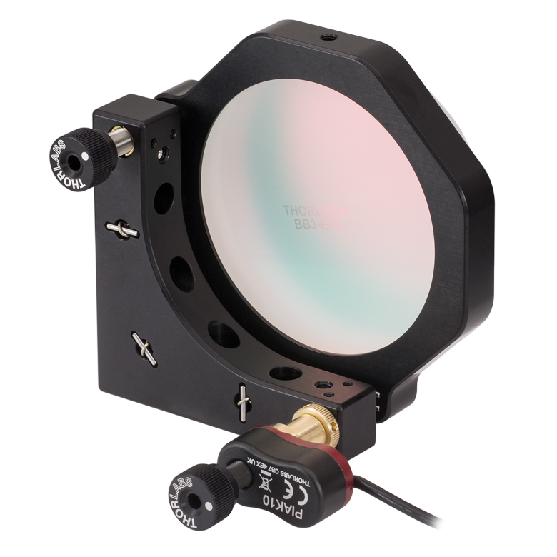
Click to Enlarge
Figure G7.2 KS3とピエゾ慣性アクチュエータPIAK10

Click to Enlarge
Figure G7.1 正面
- 先端がナイロン製の止めネジ(セットスクリュ)付き2重穴で光学素子を固定
- 厚みのある背面プレートと強力バネにより安定性が改善
- 黒色アルマイト加工
- キネマティック接触点に使用されている硬化ステンレスが摩耗を低減
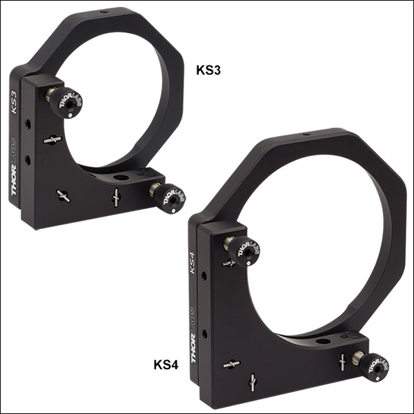
精密キネマティックミラーマウントKS3はØ75 mm~Ø76.2 mm(Ø3インチ)の光学素子、KS4はØ101.6 mm(Ø4インチ)の光学素子用に設計されており、±4°のあおり調整(ピッチ&ヨー)が可能です。マウント質量の増加に加え、全ての接触面に剛性の強化されたバネと硬化インサートが組み込まれているので、全体的な性能が向上しています。
1/4"-80 TPIの固定可能なアジャスタが2つ付いていて、±4°の角度調整が可能です。 真ちゅうのブッシュが付いたステンレススチール製の送りネジがスムーズな調整を行います。 M4ザグリ穴が4つあり、左手系、右手系のどちらの向きにもポストの取付けが可能です。
| Item # | Optic Diameter | Minimum Optic Thickness | Optical Axis Height | Angular Adjustment | Number of Adjustersa | Type of Adjustersa | Adjuster Thread | Mounting |
|---|---|---|---|---|---|---|---|---|
| KS3 | 3" or 75.0 mm | 0.28" (7.1 mm) | 2.13" (54.1 mm) | ±4º | 2 | Removable Knobs | 1/4"-80 | #8 (M4) Counterbored Holes, 4 Places |
| KS4 | 4" b | 0.28" (7.1 mm) | 2.85" (72.4 mm) | ±4º | 2 | Removable Knobs | 1/4"-80 | #8 (M4) Counterbored Holes, 4 Places |

 ズーム
ズーム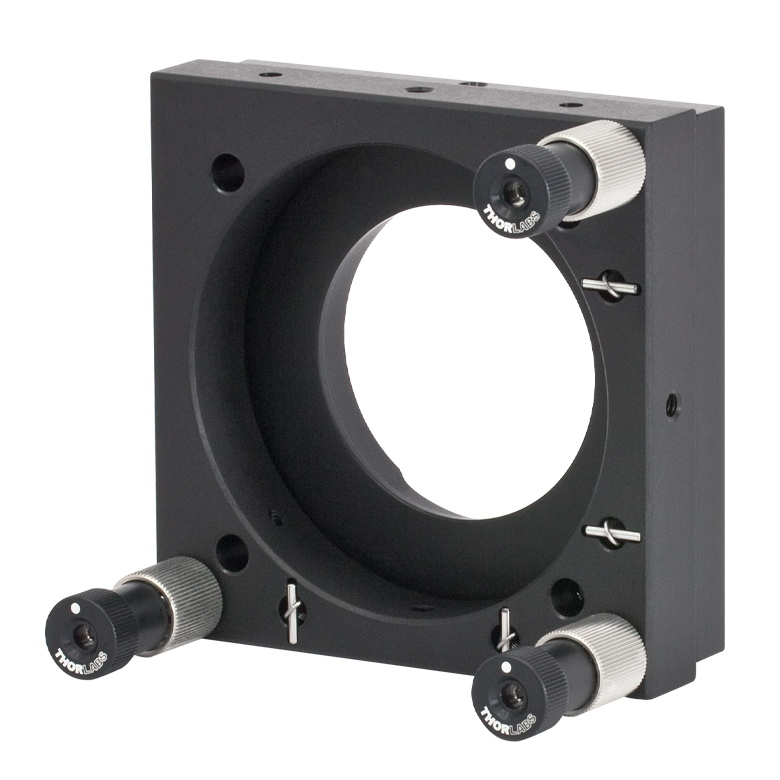
Click to Enlarge
Figure 204A KC2L(/M)の背面
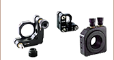
- 60 mmケージシステムの光軸上にØ50 mm~Ø50.8 mm(Ø2インチ)光学素子の取付け
- ERケージロッド用の貫通穴付き
- ±3º のキネマティックあおり調整(チップ&チルト)
- KC2L/Mに取り付けられる光学素子の最小の厚さ:3.0 mm
- KC2T/Mに取り付けられる光学素子の最大の厚さ:5.0 mm
- ポスト取付け可能な3つのM4タップ穴
キネマティックマウントKC2L/Mには、Ø50 mm~Ø50.8 mm(Ø2インチ)光学素子を取付けられるように設計された2重穴があり、光学素子は先端がナイロン製のロックネジで固定します。キネマティックマウントKC2T/Mは、中央にSM2内ネジ付きの光学素子取付け穴があり、固定リングSM2RR が2個付属しています。この取付け穴には当社のSM2シリーズレンズチューブシステムを取り付けることができます。
キネマティックマウントKC2L/MとKC2T/Mには、3つの100 TPI調整ネジが用いられており、滑らかで高分解能な動作が可能です。各アジャスタは個別に固定することができ、アジャスタを位置ずれさせずに締め付けられるコレットが付いています。ケージシステムやポストに取り付けたとき、頑丈な構造設計により優れた安定性が得られます。前面プレートと背面プレートには、当社の60 mmケージシステムに直接取り付けられるように、ケージロッド用の4つの貫通穴があります。背面プレートにはケージロッドの位置を固定するためのロック用止めネジが付いています。前面プレートのケージロッド用の穴は十分大きく作られているため、ケージロッドと接触せずに ±3ºのあおり調整(チップ&チルト)ができます。
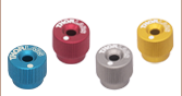
つまみネジ型六角レンチ")
 ズーム
ズーム
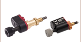
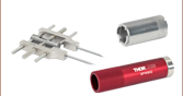
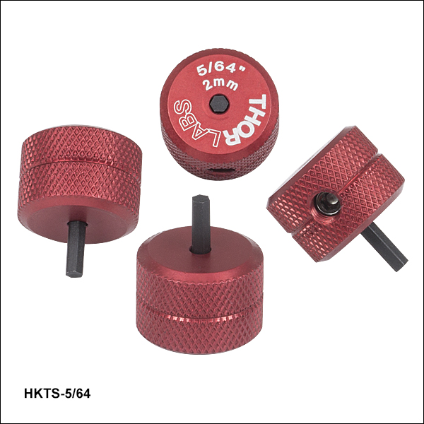
- 2 mm(5/64インチ)の六角レンチを使用するアクチュエータの調整に便利
- 赤色アルマイト加工の調整ノブで六角レンチのサイズが刻印
- 六角チップは取り替え可能
- 1パック4個入り
この2 mm(5/64インチ)六角レンチ型の調整用つまみネジを使用することで、2 mm六角レンチで調整するアクチュエータ(またはノブを取り外した標準タイプのアクチュエータ)が迅速に調整できます。 これは取り外し可能なノブであるため、調整の合間にネジの六角穴に取り付けたままにしておくことができて便利です(Figure 206A参照)。 #8-32止めネジ(2 mm六角)が取り替え可能の六角形のビットを固定します。この取り替え可能なビットは、一方の先端がつぶれてしまっても、逆向きで再利用できます。 交換用の六角レンチ型ビットが必要な場合には、当社にお問い合わせください。
つまみネジ型六角レンチには、0.050~3/16インチと2 mm~5 mmのサイズの製品があります。

 ズーム
ズーム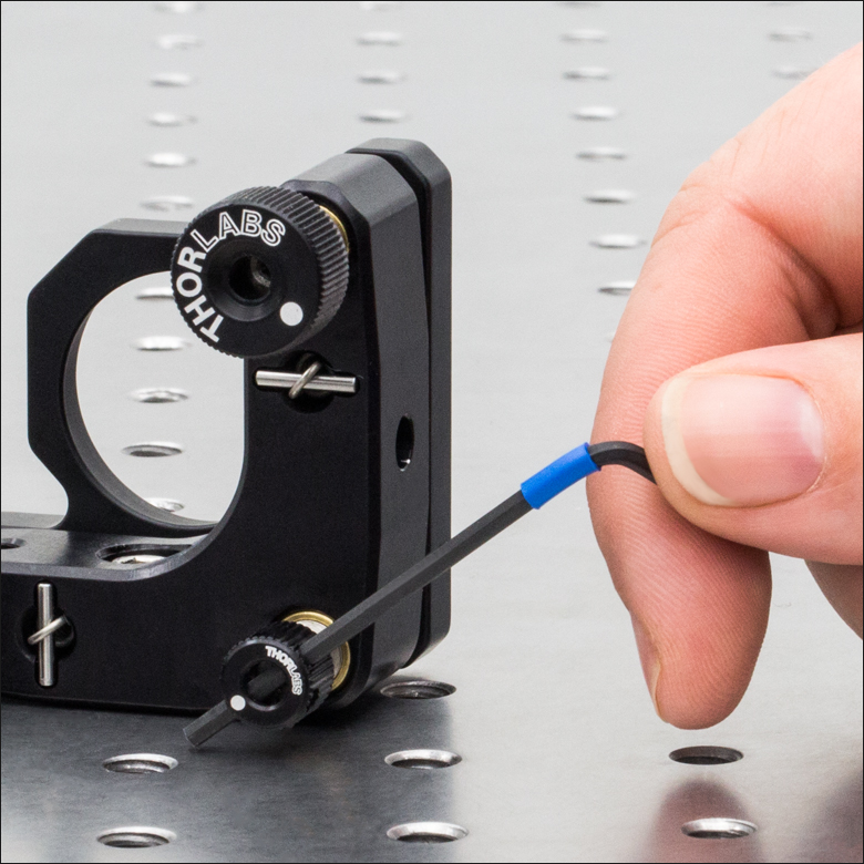
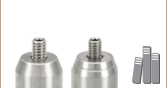
Click to Enlarge
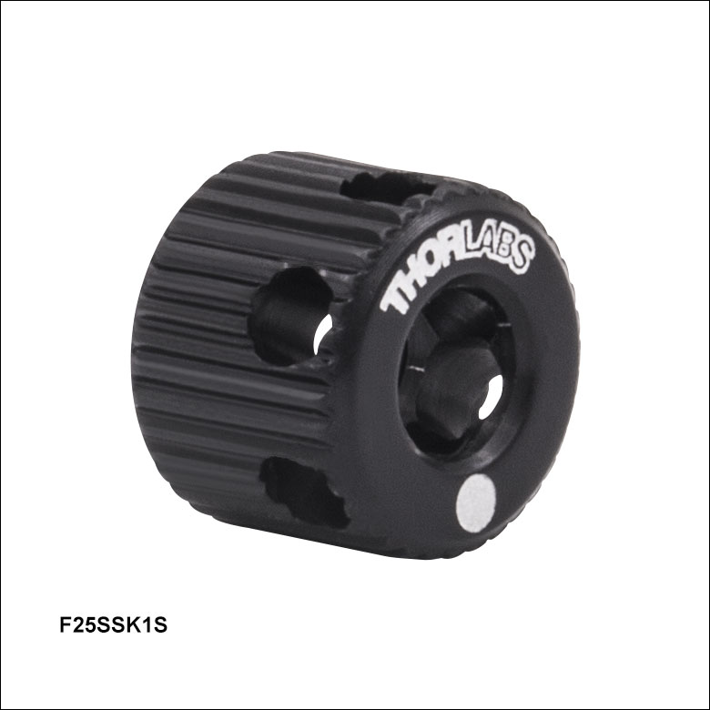
Figure 205A F25SSK1Sは小径で、側面には微調整用の横穴が付いています(2.0 mm六角レンチ使用)。
- 1/4"-80アジャスタと使用
- ボール(六角)ドライバ用のØ3.8 mm貫通穴
- ノブの側面には2.0 mmボールドライバが挿しこめる2.4 mmの穴が6個
- 直径8.9 mm
取り外し可能な低頭アジャスターノブF25SSK1Sを、当社の多くのキネマティックマウントに使用されているF25SSシリーズの1/4"-80六角アジャスタに取り付けることで、六角レンチを用いずにアジャスタの調整ができます。これにより、幅広い用途において素早く簡単な調整が行えるようになります。また、ノブの外径には6つの穴が等間隔で開いており、2.0 mmボールドライバ等を挿し込むことができます(Figure 205A参照)。 この穴を使用してより精密な調整が行え、実験用セットアップ内のノブ周辺に十分なスペースがない場合にも簡単にノブを回して調整できます。直径Ø8.9 mmと小型なため、KS1のようなキネマティックマウントを光学テーブルやブレッドボードに直接取り付けても干渉しません(Figure 205A参照)。