 Products Home / レーザー光源および関連製品 / フェムト秒レーザ / Menlo Femtosecond Fiber Lasers / Asynchronous Optical Sampling (ASOPS) Technique
Asynchronous Optical Sampling (ASOPS) Technique
- Solutions for Pump-Probe and Two-Color Pump-Probe Spectroscopy
- High-Speed Scanning
- No Mechanical
Adjustment Necessary
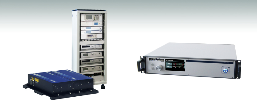
ASOPS-TWIN
Asynchronous Optical Sampling System
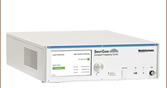
RRE-SYNCRO
Repetition Rate Stabilization


Please Wait
 Jason Reeves Menlo Systems |
Feedback? Questions? Need a Quote? Please note that these ASOPS and Repetition Rate Stabilization Systems are available directly from Menlo Systems, Inc. within the United States and from Menlo Systems GmbH outside the United States. |
| United States Phone: +1-303-635-6406 Email: ussales@menlosystems.com |
|
| Outside United States Phone: +49-89-189166-0 Email: sales@menlosystems.com |
|
Applications
ASOPS-TWIN and ASOPS-DUAL-COLOR- Pump-Probe Spectroscopy
- FTIR Spectroscopy
- Time-Domain THz Spectroscopy
- Material Characterization
- Repetition Rate Synchronization
- Precision Timing
Optional Packages
VARIO User-Defined Repetition Rate
Factory-Set Value Selectable in the 50 - 250 MHz Range
MULTIBRANCH Additional Seed Ports
Seeding of Multiple Amplifiers with Optional Subsequent Frequency Conversion to Cover Multiple Wavelengths
ASOPS-TWIN and ASOPS-DUAL-COLOR
Features
- Measurements in a 4 ns or 10 ns Time Window
- Sub-150 fs Pulses
- Fiber-Coupled or Free-Space Design
- ASOPS Control Software
- See Specs Tab for Details
In time-resolved measurements, an ultrafast pulse triggers a reaction, and a second pulse takes a snapshot of the induced change. By shifting the arrival time of the probe pulse with respect to the pump pulse, the stimulated process can be followed in time.
The Asynchronous Optical Sampling (ASOPS) technique allows for high-speed scanning over a few nanoseconds of time delay without a mechanical delay line. The ultrafast lasers delivering the pump and probe pulses are locked together at a tunable repetition rate difference. The lasers can also be locked to the same repetition rate value, and by shifting the relative phase between the laser pulses, the system will allow measurements in a reduced time window of several hundred picoseconds. Switching between the two modes can be done at the touch of a button.
RRE-SYNCRO
Features
- Synchronization to Fixed or Tunable Repetition Rate
- Relative Timing Jitter <200 fs (RMS) (0.1 Hz - 500 kHz)
- Plug-and-Play Use
- Modular Design
- Fully Customizable
- Two-Stage Locking Scheme Possible (Fundamental/Harmonic)
The RRE-SYNCRO, included with the ASOPS-TWIN and ASOPS-DUAL-COLOR, provides state-of-the-art phase lock electronics used to synchronize pulsed laser sources with high accuracy. The main application is the synchronization of a pulsed laser to a radio frequency reference, derived from a radio frequency clock or an optical reference clock. An embedded microcontroller for the stepper motor and piezo control in the laser cavity ensures long-term stability. The complete, user-friendly system allows for plug-and-play use.
| Item # | ASOPS-TWIN | ASOPS-DUAL-COLOR | |
|---|---|---|---|
| Repetition Rate | 250 MHz | 100 MHz | |
| Repetition Rate Offset Tuning Range (Δf) | ±10 kHz, in Steps of 10-5 Hz | ||
| Time Measurement Window | 4 ns | 10 ns | |
| Scan Duration (1/Δf)a | 0.1 ms @ 10 kHz Offset, 1 s @ 1 Hz Offset |
||
| Data Point Incrementb | 160 fs @ 10 kHz, 0.016 fs @ 1 Hz |
1 ps @ 10 kHz, 0.1 fs @ 1 Hz |
|
| Relative Timing Jitter (RMS) (0.1 Hz - 500 kHz) | <150 fs | ||
| Laser Head Specifications | |||
| Wavelength | 1560 nm | 1560 nm | 780 nm |
| Average Output Power | >75 mW (From Each Laser) | >100 mW | |
| Output Port | Fiber Coupled, FC/APC | Free Space | |
| Pulse Length | <150 fsc | <90 fs | <120 fs |
| Piezo Tuning Range | >625 Hz | >100 Hz | |
| Piezo Bandwidth | >30 kHz | >30 kHz | |
| Stepper Motor Tuning Range | >2 MHz | >330 kHz | |
| Trigger Signal | TTL Level at Offset Frequency, <10 ns Rise Time |
||
| Environmental Specifications | |||
| Operating Voltage | 110/115/230 VAC | ||
| Frequency | 50 to 60 Hz | ||
| Cooling Requirements | No Water Cooling Required | ||
| Operating Temperature | 22 ± 5 °C | ||
| Optical Unit Dimensions / Weight | (16.3" x 15.7" x 4.3" / 77 lbs) |
(19.7" x 21.1" x 4.3" / 77 lbs) |
|
| Control Electronics Dimensions / Weight | Mounted in 19" Rack Cabinet 800 mm x 600 mm x 1800 mm / 75 kg (31.5" x 23.6" x 70.9" / 165 lbs) |
||
| Item # | RRE-SYNCRO |
|---|---|
| Relative Timing Jitter (RMS) | <200 fs (0.1 Hz - 500 kHz)a |
| External Reference Input | 10 MHzb, Signal Level +5 dBm to +10 dBm |
| Stepper Motor Signal Output | Stepper Motor Control, Sub-D, 9 Pin |
| Piezo Signal Output | Piezo Control 0 - 150 V, BNO |
| Error Signal Output | Error Signal for Monitoring, BNC |
| Environmental Specifications | |
| Operating Voltage | 110/220 V |
| Storage Temperature | 0 to 40 °C |
| Dimensions / Weight | 449 mm x 148 mm x 317 mm / 7 kg (17.7" x 5.8" x 12.5" / 15.4 lbs) |
| Remote Control | PC Connection via |
パルスレーザ:パワーとエネルギーの計算

パルスレーザからの放射光が、使用するデバイスや用途に適合するかどうかを判断する上で、レーザの製造元から提供されていないパラメータを参照しなければならない場合があります。このような場合、一般には入手可能な情報から必要なパラメータを算出することが可能です。次のような場合を含めて、必要な結果を得るには、ピークパルスパワー、平均パワー、パルスエネルギ、その他の関連するパラメータを必要とすることがあります。
- 生物試料を損傷させないように保護する
- フォトディテクタなどのセンサにダメージを与えることなくパルスレーザ光を測定する
- 物質内で蛍光や非線形効果を得るために励起を行う
パルスレーザ光のパラメータはFigure 170AおよびTable 170Bに示します。参照用として、計算式の一覧を以下に示します。資料を ダウンロードしていただくと、これらの計算式のほかに、パルスレーザ光の概要、異なるパラメータ間の関係性、および計算式の適用例がご覧いただけます。
計算式 | ||||
 | 、 |  | ||
 | ||||
 | ||||
 | ||||
平均パワーから算出するピークパワー、ピークパワーから算出する平均パワー : | ||||
 | 、 |  | ||
| 平均パワーおよびデューティーサイクルから算出するピークパワー*: | ||||
 | *デューティーサイクル( ) はレーザのパルス光が放射されている時間の割合です。 ) はレーザのパルス光が放射されている時間の割合です。 | |||
Click to Enlarge
Figure 170A パルスレーザ光の特性を記述するためのパラメータを、上のグラフとTable 170Bに示します。パルスエネルギ (E)は、パルス曲線の下側の黄色の領域の面積に対応します。このパルスエネルギは斜線で表された領域の面積とも一致します。
| Table 170B パルスのパラメータ | |||||
|---|---|---|---|---|---|
| パラメータ | シンボル | 単位 | 説明 | ||
| パルスエネルギ | E | ジュール[J] | レーザの1周期中に放射される1パルスの全放射エネルギ。 パルスエネルギはグラフの黄色の領域の面積に等しく、 これは斜線部分の面積とも一致します。 | ||
| 周期 | Δt | 秒 [s] | 1つのパルスの開始から次のパルスの開始までの時間 | ||
| 平均パワー | Pavg | ワット[W] | パルスとして放射されたエネルギが、1周期にわたって 均一に広がっていたと仮定したときの、 光パワーの大きさ(光パワー軸上の高さ) | ||
| 瞬時パワー | P | ワット[W] | 特定の時点における光パワー | ||
| ピークパワー | Ppeak | ワット [W] | レーザから出力される最大の瞬時パワー | ||
| パルス幅 |  | 秒 [s] | パルスの開始から終了までの時間。一般的にはパルス形状の 半値全幅(FWHM)を基準にしています。 パルス持続時間とも呼ばれます。 | ||
| 繰り返し周波数 | frep | ヘルツ [Hz] | パルス光が放射される頻度を周波数で表示した量。 周期とは逆数の関係です。 | ||
計算例
下記のパルスレーザ光を測定するのに、最大入力ピークパワーが75 mW
のディテクタを使用するのは安全かどうかを計算してみます。
- 平均パワー: 1 mW
- 繰り返し周波数: 85 MHz
- パルス幅: 10 fs
1パルスあたりのエネルギは、

と低いようですが、ピークパワーは、

となります。このピークパワーはディテクタの
最大入力ピークパワーよりも5桁ほど大きく、
従って、上記のパルスレーザ光を測定するのに
このディテクタを使用するのは安全ではありません。
| Posted Comments: | |
| No Comments Posted |