 Products Home
ハードコーティングバンドパスフィルタ、マシンビジョンレンズ用
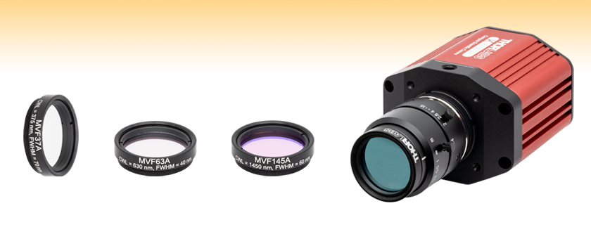
- Mounted Hard-Coated Bandpass Filters for Machine Vision Lenses with M27 x 0.5 Threads
- Center Wavelengths from 375 - 1450 nm
- Ø23.0 mm Clear Aperture
MVF37A
Machine Vision Bandpass Filter, CWL = 375 nm, FWHM = 70 nm
MVF63A
Machine Vision Bandpass Filter, CWL = 630 nm, FWHM = 40 nm
MVF37A
Machine Vision Bandpass Filter, CWL = 1450 nm, FWHM = 60 nm
Application Idea
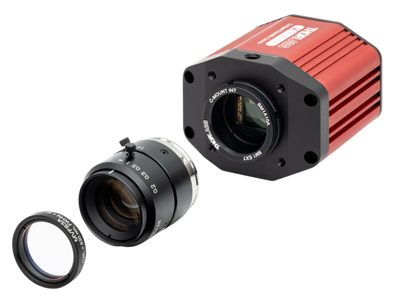
The MVF63A machine vision filter is attached to an MVL16M23 lens mounted on a CS2100M-USB camera

Please Wait
| Table 1.1 General Specifications | |
|---|---|
| Out of Band Optical Density | ODabs ≥ 2a |
| Transmission at CWL | ≥92% |
| Transmitted Wavefront Errorb | ≤0.6λ |
| Angle of Incidence | 0° |
| Housing Diameter | 29.0 mm |
| Clear Aperture | Ø23.0 mm |
| Surface Quality | 40-20 Scratch-Dig |
| Coating | Hard Coated |
| Operating Temperature | -50 to 100 °C |
| Storage Temperature | -100 to 200 °C |
| Edge Treatment | Mounted in Black Anodized Aluminum Housing |
| Edge Markings | Item #, Center Wavelength, FWHM |
| Substrate | Eagle XG® Glass |

特長
- M27 x 0.5ネジ付きマシンビジョンレンズに取り付け可能
- 中心波長375 nm~1450 nmにおける透過率 ≥ 92%
- 透過帯域幅:40 nm~85 nm
- 半円錐角(Half Cone Angle) ≤ 20°(MVF145Aは ≤ 15°)に設計
- 遮断波長範囲で優れた透過阻止特性
- ODabs ≥ 2、Tavg ≤ 0.1% (中心波長375~940 nm)
- ODabs ≥ 3、Tavg ≤ 0.01% (MVF145A)
- バンドパスフィルタのサイズは特注も可能です。詳細は当社までお問い合わせください。
当社のマシンビジョン用ハードコーティングバンドパスフィルタは、主にYb:YAGレーザ、HeNeレーザ、アルゴン(Ar)レーザ、および半導体レーザの相互のスペクトルアイソレーション(spectral isolation)を向上させるように設計されており、遮断波長域で優れた透過阻止特性(ODabs ≥ 2)が得られ、また設計波長で高い透過率(≥92%)が得られます。各バンドパスフィルタは、M27 x 0.5外ネジ付きのアルマイト処理アルミニウム製筐体に取付けられており、適合するマシンビジョンレンズに取り付けられます。
これらのフィルタの透過帯域の半値全幅(FWHM)は、選択した中心波長に依存して40~85 nmです。また、そのカットオン/カットオフの傾斜も急峻です。仕様に記載されているフィルタの中心波長と透過帯域幅は、表面に対して光が垂直に入射した場合の値です。入射角(AOI)が0°より大きい場合は、中心波長は短波長側にシフトし、透過帯域の形状も変化します。詳細は「チュートリアル」タブをご参照ください。
こちらのバンドパスフィルタは、Eagle XG®*ガラス基板に耐久性の高いスパッタリングコーティングが施されています。要件の厳しい産業分野で使用した場合でも、時間経過に対して一貫した性能が維持されます。スパッタリングで形成された薄膜コーティングは環境安定性に優れ、スペクトルが経時的にシフトしにくいという特性があります。 これらのフィルタのコーティングは、1枚の基板上に高密度に形成されるため、安定した長寿命のフィルタが得られます。このコーティングは、光学素子の標準的なクリーニング方法にも耐えられます。詳細は「光学素子の取り扱いについてのチュートリアル」をご覧ください。ソフトコーティングフィルタに比べてハードコーティングフィルタが優れている点(耐久性、透過率など)については、「比較」タブをご覧ください。これらのフィルタは工場の自動化、品質管理、ロボット工学などのほか、光学性能に一貫性が求められる様々なマシンビジョン用として適しています。
各フィルタは、黒アルマイト加工アルミニウム製の筐体に取り付けられており、筐体には型番、中心波長、およびFWHMが記載されています。これらのフィルタは当社のM27 x 0.5ネジ付きマシンビジョンレンズだけでなく、M27 x 0.5ネジ付きのマウントであれば取り付けることができます。なお、マウントからフィルタを取り外すとフィルタに損傷を与える危険性が非常に高くなるため、取り外しはお勧めいたしません。
*Eagle XG®はCorning社の登録商標です。
Click to Enlarge
Figure 1.3 光スイッチキットOSW22-633Eの画像。カメラCS165CU1にレンズMVL8M23を取り付け、さらに様々なマシンビジョンフィルタを取り付けて、異なる特徴を強調してイメージングしています。各画像を取得するのに使用したフィルタは、(a)フィルタ無し、(b)MVF52A、(c)MVF58A、(d) MVF66Aです。
| Table 1.3 Additional Bandpass Filters | ||||
|---|---|---|---|---|
| UV/VIS Hard-Coated Bandpass Filters 300 - 694 nm CWLs | NIR Hard-Coated Bandpass Filters 700 - 2000 nm CWLs | IR Bandpass Filters 1750 - 12 000 nm CWLs | Wedged Hard-Coated Bandpass Filters 532 - 785 nm CWLs | Hard-Coated Bandpass Filter Kits |
| 当社では、中心波長やFWHMの異なる、カスタムバンドパスフィルタもご提供しています。お見積りに関しては当社までお問い合わせください。 | ||||
Click to Enlarge
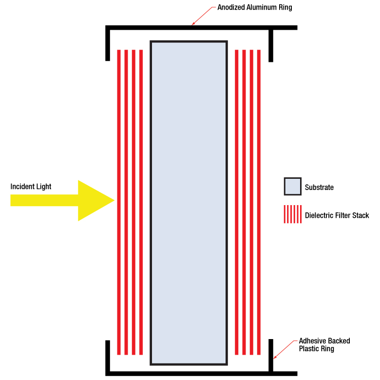
Figure 2.1 The number of layers shown in this schematic is not indicative of the number of layers in an actual hard-coated bandpass filter. The drawing is also not to scale.
Hard-Coated Bandpass Filter Structure
A bandpass filter is created by depositing layers of material on the surface of the substrate. For our hard-coated bandpass filters, the coating is comprised of dielectric stacks alternating with dielectric spacer layers. Each dielectric stack is composed of a large number of alternating layers of low-index and high-index material. The thickness of each layer in the dielectric stack is λ/4, where λ is the design center wavelength of the bandpass filter (i.e. the wavelength designed to have highest transmittance through the filter at normal incidence). The spacer layers are placed in between the stacks and have a thickness of (nλ)/2, where n is an integer. A Fabry-Perot cavity is formed by each spacer layer sandwiched between dielectric stacks. The filter is mounted in an engraved metal ring for protection and ease of handling.
Filter Operation Overview
The constructive interference conditions of a Fabry-Perot cavity allow light at the center wavelength, and a small band of wavelengths to either side, to be transmitted efficiently, while destructive interference prevents the light outside the passband from being transmitted. However, the band of blocked wavelengths on either side of the center wavelength is small. To increase the blocking range of the filter, materials with broad blocking ranges are used as the substrate or to coat the spacer layers. Although these materials effectively block out-of-band transmission of incident radiation, they also decrease the transmission through the filter in the passband.
Filter Temperature
Click to Enlarge
Figure 2.2 This plot displays the forward (solid lines) and backward (dashed lines) transmission through the FBH800-10 and FBH800-40 hard-coated bandpass filters.
The center wavelength of the filter can be tuned slightly (~1 nm over the operating range of the filter) by changing the temperature of the filter. This is primarily due to the slight thermal expansion or contraction of the layers.
Filter Orientation
Direction of Transmission
An engraved arrow on the edge of the filter is used to indicate the recommended direction for the transmission of light through the filter. Orienting the coated side toward the source will reduce unwanted scattering and minimize reflections sent back toward the source. Using the filter in the opposite orientation will not, however, significantly affect the performance of the filter. Figure 2.2 was made by illuminating the filter with a low intensity broadband light and measuring the transmission as a function of wavelength. This plot shows that the direction of transmission through the filter has very little effect on the intensity and the spectrum of the light transmitted through the filter. The minimal variation between the forward and backward traces is most likely due to a small shift in the incident angle of the light on the filter introduced when the filter was removed, flipped over, and replaced in the jig.
Angle of Incidence (AOI)
The filter is intended to be used with collimated light normally incident on the surface of the filter. For uncollimated light or light striking the surface at an angle not normally incident to the surface, the center wavelength (wavelength corresponding to peak transmission) will shift toward lower wavelengths and the shape of the transmission region (passband) will change. Varying the angle of incidence (AOI) by a small amount can be used to effectively tune the passband over a narrow range. Large changes in the incident angle will cause larger shifts in the center wavelength but will also significantly distort the shape of the passband and, more importantly, cause a significant decrease in the transmittance of the passband. Figures 2.3 through 2.6 show examples of the change of the passband, transmission, and center wavelength (CWL) with when the AOI is changed for various filters. Filters with passband full width half maxima (FWHM) in the range of 1 nm to 5 nm are particularly susceptible to these shifts and extra care should be taken to ensure they are set to the desired AOI. Figures 2.3 through 2.6 are given in order of increasing nominal passband FWHM.
Click to Enlarge
Figure 2.4 This plot displays the changing transmission and FWHM of the passband for an FLH1064-3 hard-coated bandpass filter at varying angles of incidence (AOI). The design CWL and passband of the FLH1064-3 filter are 1064 nm and 3 nm, respectively.
Click to Enlarge
Figure 2.3 This plot displays the changing transmission and FWHM of the passband for an FLH532-1 hard-coated bandpass filter at varying angles of incidence (AOI). The design CWL and passband of the FLH532-1 filter are 532 nm and 1 nm, respectively.
Click to Enlarge
Figure 2.6 This plot displays the changing transmission and FWHM of the passband for an FLH1030-10 hard-coated bandpass filter at varying angles of incidence (AOI). The design CWL and passband of the FLH1030-10 filter are 1030 nm and 10 nm, respectively.
Click to Enlarge
Figure 2.5 This plot displays the changing transmission and FWHM of the passband for an FBH800-10 hard-coated bandpass filter at varying angles of incidence (AOI). The design CWL and passband of the FBH800-10 filter are 800 nm and 10 nm, respectively.
Figures 2.7 through 2.11 show how the properties of the FLH532-1, FLH1064-3, and FLH1030-10 hard-coated bandpass filters change as the AOI is varied.
Click to Enlarge
Figure 2.8 This plot shows the the FWHM at the CWL corresponding to the peak transmission at the given AOI. Item #'s FLH532-1, FLH1064-3, and FLH1030-10 have design center wavelengths of 532, 1064, and 1030 nm with 1, 3, and 10 nm FWHM passbands, respectively.
Click to Enlarge
Figure 2.7 This plot displays the transmission at the design center wavelength as the angle of incidence is varied. As can be seen in this graph, the transmission of filters with wider passbands are less sensitive to changes in the AOI. Item #'s FLH532-1, FLH1064-3, and FLH1030-10 have design center wavelengths of 532, 1064, and 1030 nm with 1, 3, and 10 nm FWHM passbands, respectively.
Click to Enlarge
Figure 2.11 This plot displays the center wavelength that provides the maximum transmission for a given angle of incidence for an FLH1030-10 hard-coated bandpass filter with a design CWL of 1030 nm and a passband FWHM of 10 nm.

Click to Enlarge
Figure 2.10 This plot displays the center wavelength that provides the maximum transmission for a given angle of incidence for an FLH1064-3 hard-coated bandpass filter with a design CWL of 1064 nm and a passband FWHM of 3 nm.
Click to Enlarge
Figure 2.9 This plot displays the center wavelength and peak transmission at that wavelength for a given angle of incidence for an FLH532-1 hard-coated bandpass filter with design CWL of 532 nm and passband FWHM of 1 nm.
Filter Reflectance
Thorlabs' hard-coated bandpass filters reflect out-of-band light with high efficiency. Figure 2.12 shows the measured reflectance of an FBH1200-10 hard-coated bandpass filter with a design CWL of 1200 nm and passband FWHM of 10 nm. The blocking region for this filter is specified as ODabs > 5 between the ranges of 200 - 1180 nm and 1220 - 1700 nm.
Click to Enlarge
Figure 2.12 This plot displays the reflectance of an FBH1200-10 hard-coated bandpass filter over an extended range from 200 nm to 1800 nm. As can be seen in the graph, the filter reflectance is high within the blocking region of 200 - 1180 nm and 1220 - 1700 nm. The drop in reflectance below 300 nm is due to increased absorption by the glass substrate.
Out-of-Band Filter Performance
The transmission and optical density properties of the hard-coated bandpass filters will vary for far out-of-band wavelengths. Figures 2.13 and 2.14 show the variation in transmission and optical density for wavelengths far outside the specified blocking regions of 200 - 379 nm and 401 - 1200 nm for an FBH390-10 hard-coated bandpass filter. The FBH390-10 has a design CWL of 390 nm and a passband FWHM of 10 nm. The blocking region is specified to be ODabs > 5 between the ranges of 200 - 379 nm and 401 - 1200 nm.
Click to Enlarge
Figure 2.14 This plot displays the optical density (OD) measured between 200 nm and 1600 nm for the FBH390-10 hard-coated bandpass filter. The OD drops off for wavelengths beyond 1200 nm.
Click to Enlarge
Figure 2.13 This plot displays the transmission through an FBH390-10 hard-coated bandpass filter over an extended range from 200 nm to 1600 nm. The transmission varies for wavelengths beyond 1200 nm.
ハードコーティングフィルタの利点
ソフトコーティングフィルタの構造
 Click to Enlarge
Figure 24A ソフトコーティングフィルタは、基板層に挟まれた誘電体多層膜を利用します。この図に示されている層の数は実際のバンドパスフィルタにおける層の数を表すものではなく、また縦横比も実際とは異なります。
ハードコーティングフィルタの構造
 Click to Enlarge
Figure 24B ハードコーティングフィルタでは、蒸着は基板表面に施されます。この図に示されている層の数は実際のハードコーティングバンドパスフィルタにおける層の数を表すものではありません。この図面の縦横比も実際とは異なります。
ソフトコーティングとハードコーティングのフィルタは、光学製品として一般的に販売されています。 ソフトコーティングフィルタは、化学的に反応しやすい層の積層構造になっているため、温度安定性が低い、透過率が低い、光散乱が大きい、保存寿命が短いといった問題があります。ハードコーティングフィルタは、高エネルギースパッタリング技術によって光学基板上に化学的に不活性な層を形成するため、そのような欠点がありません。
ソフトコーティングフィルタは、Figure 24Aに示すように、マウント内の光学基板間に挟まれた誘電体層で構成されています。誘電体層は、しばしば硫化亜鉛、氷晶石、銀などの壊れやすい材料で構成されています。これらの化学物質は水と反応してフィルタの性能を劣化させるため、湿度の高い環境でのソフトコーティングフィルタの保存寿命は大幅に短くなります。アセンブリの密封部分は環境、取り扱い方、フィルタの組立工程の品質などにより、いずれは機能しなくなり、それに伴って光学性能は急速に低下します。これらの要因により、ソフトコーティングフィルタの寿命は、研究室環境では通常1年から5年です。
ソフトコーティングフィルタが積層構造を有するということは、温度変化がフィルタの光学性能に重大な影響を及ぼすことを意味します。誘電体多層膜、エポキシ、光学基板、吸収ガラス、マウントの熱膨張係数は、一般にはすべて異なるでしょう。その結果、温度変化によってフィルタの形状が予想外に変化することがあります。
ハードコーティングフィルタでは、ガラス基板上に誘電体層をスパッタリングによって作成します。この誘電体多層膜にはソフトコーティングフィルタに使用される材料よりも環境に対して安定な材料が使用されるため、Figure 24Bに示すように性能を低下させることなく環境にさらすことができます。ハードコーティングフィルタはソフトコーティングフィルタよりも薄いため、スペースが限られた用途でも容易に組み込むことができます。スパッタリング工程は自動化されており、再現性が高く、コーティングされていない光学部品に近い透過波面誤差が得られます。
ソフトコーティングフィルタの可視(VIS)波長域での透過率は、銀を使用しない場合で約80%、誘電体多層膜に銀を使用した場合は約50%に制限され、紫外域の透過率はさらに制限されます。Figure 24CとFigure 24Dに示すように、ハードコーティングフィルタでは紫外(UV)域および可視(VIS)域での透過率が向上します。ハードコーティングフィルタのカットオンとカットオフの傾斜は、ソフトコーティングフィルタに比べて急峻です。またハードコーティングフィルタの透過率はソフトコーティングフィルタに比べて平坦です。これは、より複雑なキャビティーフィルタを高い精度と再現性で蒸着できるスパッタリング工程を使用しているためです。
 Click to Enlarge
Figure 24D ハードコーティングフィルタとソフトコーティングフィルタのUV域での性能比較
 Click to Enlarge
Figure 24C ハードコーティングフィルタとソフトコーティングフィルタの可視域での性能比較
| Posted Comments: | |
| No Comments Posted |
| Table G1.1 Specifications | ||||||||
|---|---|---|---|---|---|---|---|---|
| Item #a | Center Wavelengthb | FWHM Bandwidth | Blocking Regions (Optical Density, Transmission) | Transmission Datac | Transmission | Half Cone Angle | Clear Aperture | Outer Diameter |
| MVF37A | 375 nm | 70 nm | 300 - 328 nm, 415 - 1000 nm (ODabs ≥ 2, Tavg ≤ 0.1%) 1000 - 1100 nm (Tavg ≤ 3.1%) | ≥92%, 345 - 405 nm | ≤20° | Ø23.0 mm | Ø29.0 mm | |
| MVF40A | 405 nm | 40 nm | 300 - 379 nm, 434 - 1050 nm (ODabs ≥ 2, Tavg ≤ 0.1%) | ≥92%, 390 - 420 nm | ||||
| MVF46A | 460 nm | 85 nm | 300 - 406 nm, 507 - 1050 nm (ODabs ≥ 2, Tavg ≤ 0.1%) | ≥92%, 420 - 495 nm | ||||
| MVF52A | 525 nm | 40 nm | 300 - 495 nm, 558 - 1050 nm (ODabs ≥ 2, Tavg ≤ 0.1%) | ≥92%, 510 - 540 nm | ||||
| MVF58A | 585 nm | 40 nm | 300 - 556 nm, 614 - 1050 nm (ODabs ≥ 2, Tavg ≤ 0.1%) | ≥92%, 570 - 600 nm | ||||
| MVF63A | 630 nm | 40 nm | 300 - 601 nm, 660 - 1050 nm (ODabs ≥ 2, Tavg ≤ 0.1%) | ≥92%, 615 - 645 nm | ||||
| MVF66A | 660 nm | 60 nm | 300 - 615 nm, 707 - 1050 nm (ODabs ≥ 2, Tavg ≤ 0.1%) | ≥92%, 635 - 685 nm | ||||
- すべての仕様値は入射角0°の場合に有効です。
- 当社のすべてのマシンビジョンフィルタの中心波長での透過率は≥92%です。
- グラフと生データ(ダウンロード可能)は
 をクリックしてご覧ください。ただし、透過率として保証されるのは上に記載された波長範囲の透過率のみであり、またグラフのデータは典型値ですのでご注意ください。性能は製造ロット毎に異なる場合があります。
| Table G2.1 Specifications | ||||||||
|---|---|---|---|---|---|---|---|---|
| Item #a | Center Wavelengthb | FWHM Bandwidth | Blocking Regions (Optical Density, Transmission) | Transmission Datac | Transmission | Half Cone Angle | Clear Aperture | Outer Diameter |
| MVF78A | 785 nm | 40 nm | 300 - 753 nm, 816 - 1050 nm (ODabs ≥ 2, Tavg ≤ 0.1%) | ≥92%, 771 - 799 nm | ≤20° | Ø23.0 mm | Ø29.0 mm | |
| MVF85A | 850 nm | 40 nm | 300 - 817 nm, 885 - 1100 nm (ODabs ≥ 2, Tavg ≤ 0.1%) | ≥92%, 834 - 866 nm | ||||
| MVF94A | 940 nm | 50 nm | 300 - 897 nm, 984 - 1150 nm (ODabs ≥ 2, Tavg ≤ 0.1%) | ≥92%, 920 - 960 nm | ||||
| MVF145A | 1450 nm | 60 nm | 300 - 1372 nm, 1540- 2000 nm (ODabs ≥ 3, Tavg ≤ 0.01%) | ≥92%, 1435 - 1465 nm | ≤15° | |||
- すべての仕様値は入射角0°の場合に有効です。
- 当社のすべてのマシンビジョンフィルタの中心波長での透過率は≥92%です。
- グラフと生データ(ダウンロード可能)はをクリックしてご覧ください。ただし、透過率として保証されるのは上に記載された波長範囲の透過率のみであり、またグラフのデータは典型値ですのでご注意ください。性能は製造ロット毎に異なる場合があります。