 Products Home
自動ゴニオステージ、±30°回転、ステッピングモータ、コントローラ内蔵
- ±30° or ±50° Pure Rotational Motion About a Fixed Axis Above the Stage
- Closed-Loop Operation with Down to ±50 µrad Accuracy
- Integrated Stepper Motor and Controller
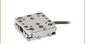
GNM1
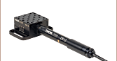
Single-Axis Motorized Goniometer,
±30° Travel, 30 mm to Point of Rotation
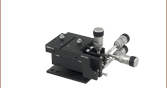
Application Idea
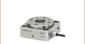
ORIC® PDR1 Rotation Stage Mounted on
GNM1 Stage Shown at -30° Position
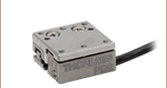
GNM2
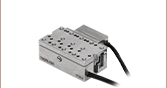
Single-Axis Motorized Goniometer,
±50° Travel, 70 mm to Point of Rotation
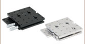
GNM3
Single-Axis Motorized Goniometer,
±50° Travel, 120 mm to Point of Rotation


Please Wait
Click for Details
Figure 1.3 GNM3(/M) Moving World Mounting Options

Click for Details
Figure 1.2 GNM2(/M) Moving World Mounting Options

Click for Details
Figure 1.1 GNM1(/M) Moving World Mounting Options
Features
- Pure Rotational Motion About a Fixed Virtual Axis
- Integrated Stepper Motor & Controller
- Remote Control via Kinesis Software & Manual Control Using On-Unit Buttons
- 5 V TTL Input and Output Trigger Ports
- 2° Graduation Markings on Side
- Three Sizes Available with ±30° (Item # GNM1(/M)) or ±50° (Item #s GNM2(/M) and GNM3(/M)) Translation
- Manual and Motorized ±8°/±5° Goniometer Stages Also Available
Click to Enlarge
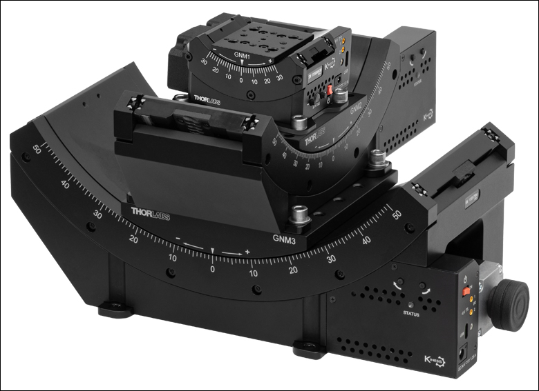
Figure 1.6 A GNM1 goniometric stage is mounted on the larger GNM2 stage which is mounted on the larger GNM3 stage; this configuration results in a common virtual pivot point between the three stages, providing pure spherical motion. Since the GNM1 stage is parallel to the GNM3 stage and they are separated by 50.0 mm vertically, they share a common axis of rotation and translation in this direction is extended to up to 80°.
Click to Enlarge
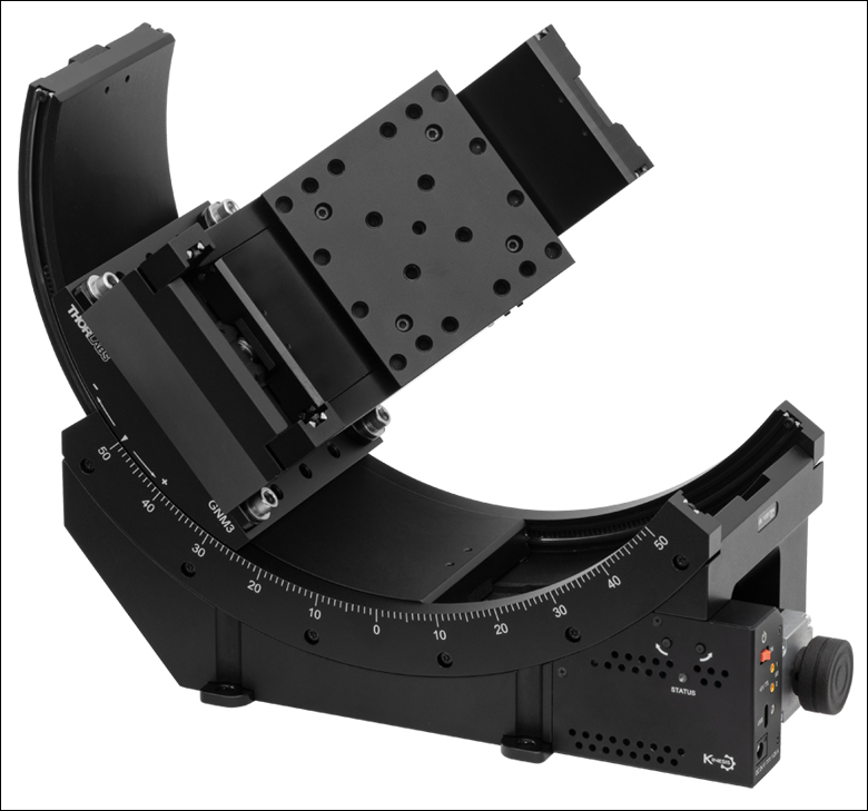
Figure 1.5 A GNM2 goniometric stage is mounted on the larger GNM3 stage, resulting in a common pivot point between the two stages and providing pure spherical motion up to 50° in any direction.
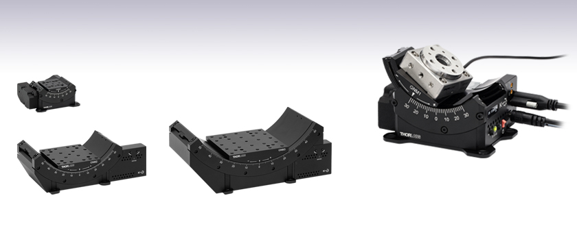
The GNMx(/M) series of motorized goniometers offer unobstructed, pure rotational motion about their virtual axes of rotation. They each feature an integrated microstepping motor, optical encoder, and controller designed for remote operation, as well as jog buttons on the side for manual actuation. Input and output triggers enable external triggering using 5 V TTL signals.
The GNM1(/M) goniometer rotates its 40.0 mm x 50.0 mm (1.57" x 1.97") moving platform over a ±30° range, 30 mm above the moving platform surface (see Figure 1.4). The GNM2(/M) and GNM3(/M) goniometers rotate their 86.0 mm x 94.0 mm (3.39" x 3.70") or 120.0 mm x 120.0 mm (4.72" x 4.72") moving platforms, respectively, over a ±50° range, with axis of rotation 70 mm or 120 mm above their moving platform surfaces (see Figure 1.4).
These goniometers are designed to stack while maintaining a common virtual axis of rotation or pivot point. Because the distance from the center of the top mounting surface to the rotation axis on the larger stages matches the distance from the bottom surface to the axis on the next smaller stage, they can be combined to extend travel or enable spherical translation in a perpendicular direction. For example, stacking a GNM2 medium stage on a GNM3 large stage and a GNM1 small stage on the GNM2 medium stage as shown in Figure 1.6 results in up to 80° of travel in one direction and 50° of travel in the perpendicular spherical coordinate.
Click to Enlarge
Figure 1.4 Representative Motorized Goniometer Diagram
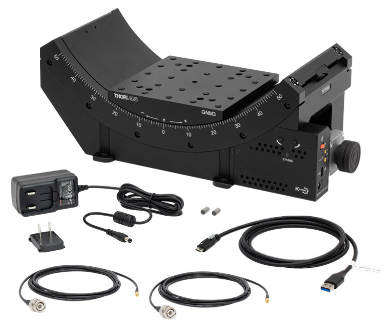
These stages are compatible with our Kinesis software package, which can be downloaded here. Please see the Kinesis Software tab for more information. A CABCUL72 locking USB Type-C cable is included for remote connections, as well as two CA3272 MMCX-to-BNC input and output trigger cables, and a KPS201 15 VDC power supply (Item # GNM1(/M)) or 24 VDC power supply (Item #s GNM2(/M) and GNM3(/M)). CA3439 MMCX-to-SMA cables are available separately.
The GNM1(/M) stage provides an array of mounting holes for compatibility with ORIC piezo inertia rotation and translation (5 mm and 20 mm) stages as well as general optomech, while the larger GNM2(/M) and GNM3(/M) stages provide arrays of 1/4"-20 (M6 x 1.0) mounting holes for mounting general optomechancial components and many of our other stages; click Figures 1.1, 1.2, and 1.3 for details. The base of each stage features either three or four 1/4" (M6) mounting bores that are compatible with imperial or metric hole patterns. Dowel pin holes on the moving platform and base of each stage enable precise positioning using the included dowel pins.
An individualized test report is included with each stage to provide an overview of measured performance; click here for a sample report. Testing data can be obtained using the serial number on the stage via the product page links below.
| Item # | GNM1(/M) | GNM2(/M) | GNM3(/M) |
|---|---|---|---|
| Stage Specifications | |||
| Distance from Top Surface to Axis of Rotation (H) |
30.00 mm ± 0.01 mm (1.18" ± 0.0004") |
70.00 mm ± 0.01 mm (2.76" ± 0.0004") |
120.00 mm ± 0.01 mm (4.72" ± 0.0004") |
| Distance from Bottom Surface to Axis of Rotation |
70.00 mm ± 0.01 mm (2.76" ± 0.0004") |
120.00 mm ± 0.01 mm (4.72" ± 0.0004") |
190.00 mm ± 0.01 mm (7.48" ± 0.0004") |
| Platform Size | 40.0 mm x 50.0 mm (1.57" x 1.97") |
86.0 mm x 94.0 mm (3.39" x 3.70") |
120.0 mm x 120.0 mm (4.72" x 4.72") |
| Centered Load Capacity (P) | 20 N / 2.03 kg (4.47 lbs) | 60 N / 6.10 kg (13.45 lbs) | 200 N / 20.40 kg (44.97 lbs) |
| Off-Center Load (Q) | ≤ 20 / (1 + D/40) N (D = Cantilever Dist. in mm) |
≤ 60 / (1 + D/40) N (D = Cantilever Dist. in mm) |
≤ 200 / (1 + D/40) N (D = Cantilever Dist. in mm) |
| Max Torque (My) | 0.5 N•m | 1.18 N•m | 7.8 N•m |
| Travel | ±30° | ±50° | |
| Speed Range | 0.005 - 25 °/s | 0.001 - 50 °/s | |
| Max Acceleration (2 kg Load) | 25 °/s2 | 50 °/s2 | |
| Bidirectional Repeatability | ±50 µrad | ±25 µrad | |
| Home Location Repeatability | ±50 µrad | ±25 µrad | |
| Min Repeatable Incremental Movementa | 90 µrad | 50 µrad | |
| Position Angle Accuracy (A) | ±150 µrad | ±75 µrad | ±50 µrad |
| Yaw Angular Deviationb | 400 µrad | 300 µrad | 200 µrad |
| Roll Angular Deviationc | 400 µrad | 300 µrad | 200 µrad |
| Radius of Confusion (R)d | <40 µm Max | <60 µm Max | |
| Motor Specifications | |||
| Motor Type | Stepper with Microsteps | ||
| Motor Drive Voltage | ±15 V | ±24 V | |
| Max Motor Drive Current | <150 mA | <700 mA | <1 A |
| Motion Control Algorithm | Exponential Approach Algorithm | ||
| Quadrature Encoder Resolution | 0.1 µm | ||
| Velocity Profile | Trapezoidal | ||
| Voltage | 15 V Regulated DC | 24 V Regulated DC | |
| Current | 500 mA (Peak) | 1 A (Peak) | 1.25 A (Peak) |
| General Specifications | |||
| Dimensions (W x D x H) at Mid Travel |
97.0 mm x 82.4 mm x 42.7 mm (3.82" x 3.24" x 1.68") |
242.0 mm x 112.0 mm x 74.9 mm (9.53" x 4.50" x 2.95") |
299.0 mm x 137.0 mm x 110.3 mm (11.77" x 5.46" x 4.34") |
| Mass (Without Cables) | 0.45 kg (0.99 lbs) | 2.37 kg (5.22 lbs) | 5.70 kg (12.57 lbs) |
Specification Details
Centered Load Capacity
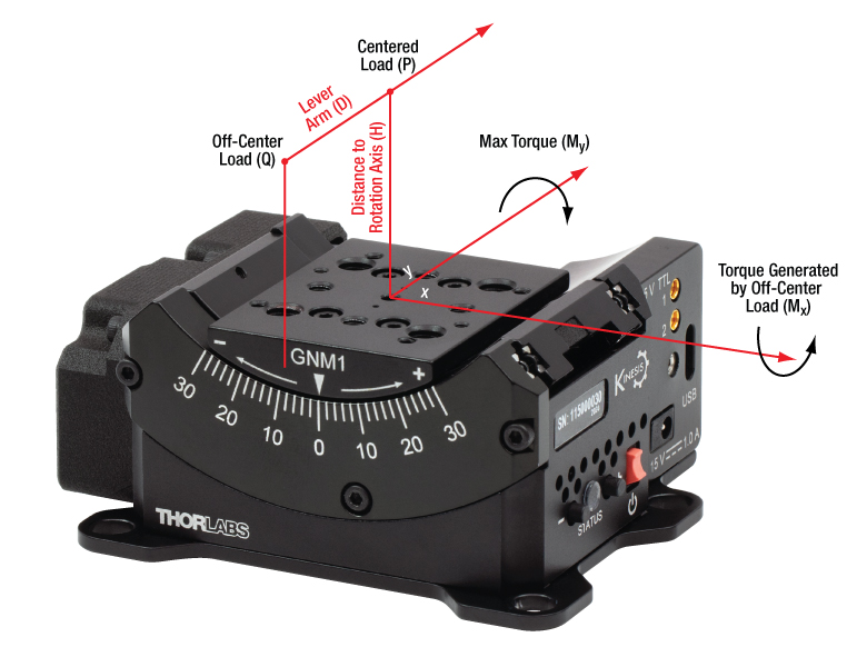
Click to Enlarge
Figure 2.1 Load Capacity Illustration
- Centered Load capacity is specified for a load with a center of mass located on the rotation axis and above the top plate's center (P).
- If the load is displaced along the rotation axis, then it generates Mx torque and should be decreased according to the formula: Q≤P/(1+D/k) (N). P is the max centered load capacity of the stage in N and D is the lever arm distance in mm. The coefficient “k” depends on a number of factors but is equal to 40 mm for each of the GNMx stages; for the GNM1 stage, the load should be less than 20/(1+D/40) Newtons.
- If the load is moved out of the rotation axis, it generates My torque, which is limited by the Max Torque parameter. My torque should not exceed Max Torque during the whole travel range.
Yaw & Roll Deviation

Click to Enlarge
Figure 2.2 Yaw & Roll Deviation Illustration
Click to Enlarge
Figure 2.3 Sample Yaw & Roll Deviation Measurements
- The Z axis is specified as the line through the center of the top plate that is perpendicular to the axis of rotation.
- Yaw is the rotation angle of the top plate around the Z axis, assuming the homing position is zero.
- Roll is the rotation angle of the top plate around the X axis, assuming the homing position is zero.
- The yaw and roll deviations are calculated as the difference between maximum and minimum values.
Accuracy
Click to Enlarge
Figure 2.4 Sample Accuracy Measurements
- Accuracy refers to a maximum positioning error.
- The position angle is calculated as the angle between the projections to the XZ plane of the normal vectors to the top plate surface in the current and homed positions.
Radius of Confusion
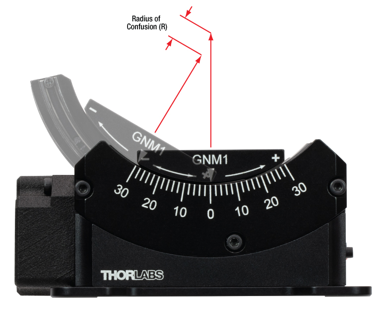
Click to Enlarge
Figure 2.5 Radius of Confusion Illustration
- Radius of confusion refers to the amount of deviation shown by a fixed point that is securely attached to the top plate and positioned along a rotational axis in a central homing position above the center of the top plate.
- It is calculated as the maximum distance between the calculated points during rotation and the one at the homed position.
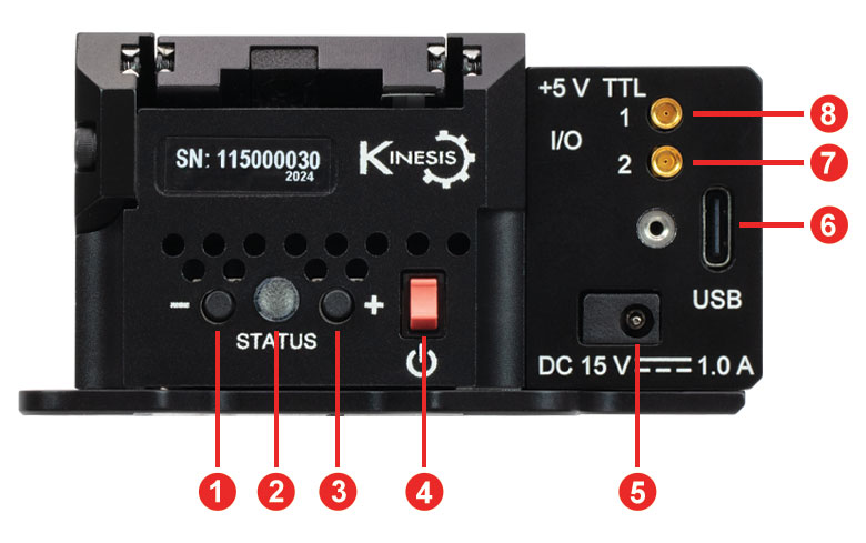
Click to Enlarge
Figure 3.1 GNM1(/M)の側面パネル
| Side Panel | |
|---|---|
| Callout | Description |
| 1 | Reverse Jog Button |
| 2 | Status LED |
| 3 | Forward Jog Button |
| 4 | Power Switch |
| 5 | Power Supply Connector |
| 6 | USB Type-C Connectora |
| 7 | Input Connector, MMCX Socket, 5 V TTLb |
| 8 | Output Connector, MMCX Socket, 5 V TTLb |
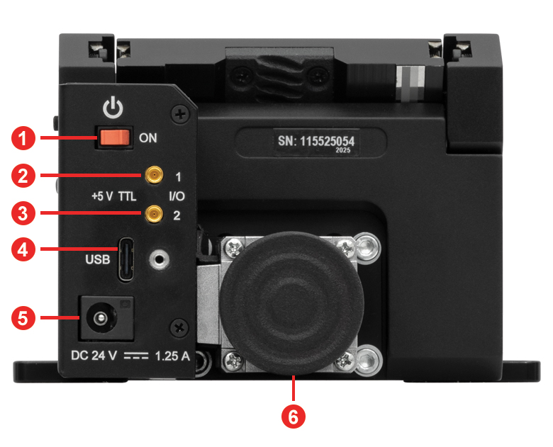
Click to Enlarge
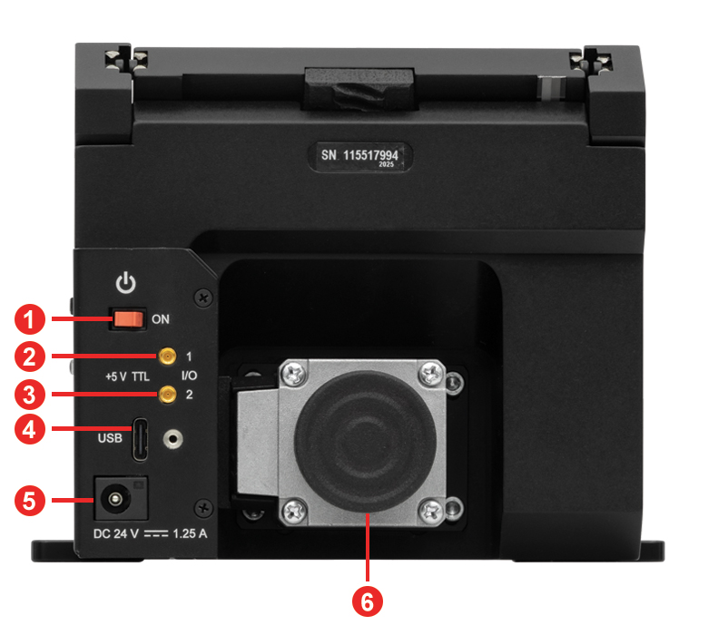
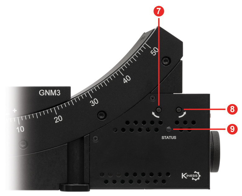
Figure 3.3 GNM2(/M) Side Panel
Click to Enlarge
Figure 3.4 GNM2(/M) Front Panel
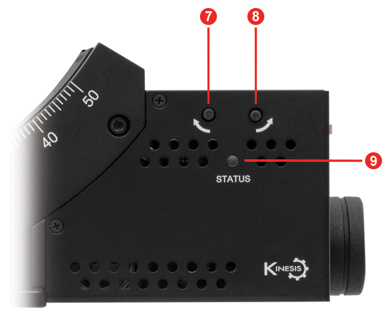
| Table 3.5 GNM2(/M) Side Panel | |
|---|---|
| Callout | Description |
| 1 | Power Switch |
| 2 | Output Connector, MMCX Socket, 5 V TTLa |
| 3 | Input Connector, MMCX Socket, 5 V TTLa |
| 4 | USB Type-C Connectorb |
| 5 | Power Supply Connector |
| 6 | Knob for Manually Moving the Stagec |
| 7 | Reverse Jog Button |
| 8 | Forward Jog Button |
| 9 | Status LED |
Click to Enlarge
Figure 3.6 GNM3(/M) Side Panel
Click to Enlarge
Figure 3.7 GNM3(/M) Front Panel
| Table 3.8 GNM3(/M) Side Panel | |
|---|---|
| Callout | Description |
| 1 | Power Switch |
| 2 | Output Connector, MMCX Socket, 5 V TTLa |
| 3 | Input Connector, MMCX Socket, 5 V TTLa |
| 4 | USB Type-C Connectorb |
| 5 | Power Supply Connector |
| 6 | Knob for Manually Moving the Stagec |
| 7 | Reverse Jog Button |
| 8 | Forward Jog Button |
| 9 | Status LED |
Click to Enlarge
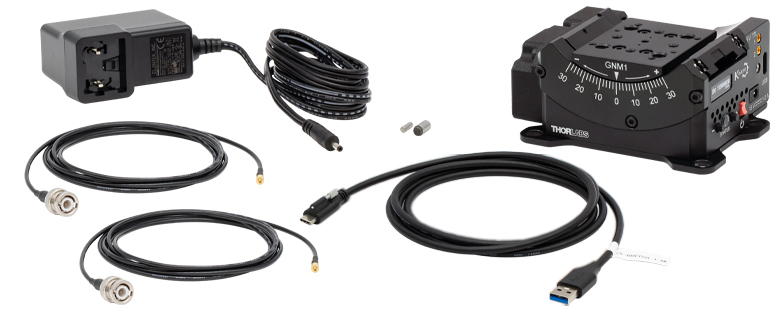
Figure 4.1 ステージGNM1/Mに含まれるコンポーネント
発送品リスト
- ゴニオステージ
- 電源KPS201、15 VDC、2.4 A
- MMCXオス-BNCオスケーブルCA3272、長さ1.8 m(2本)
- 固定ネジ付きUSB 3.0 Type-A - Type-CケーブルCABCUL72
- Ø3 mm x 10 mm位置決めピン、m6公差、硬化スチール製
- Ø5 mm x 10 mm位置決めピン、m6公差、硬化スチール製
- 個別の試験報告書
Click to Enlarge
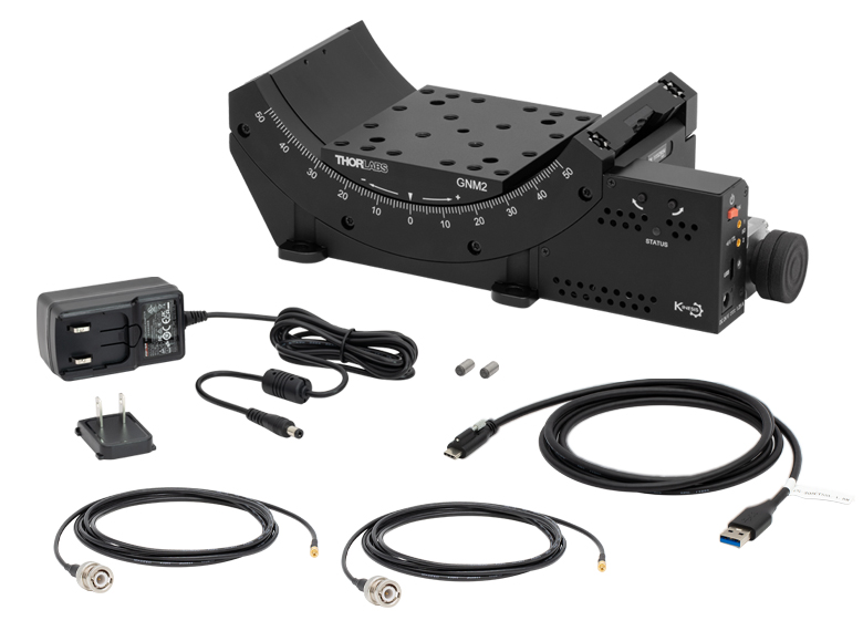
Figure 4.2 GNM2(/M) Stage Contents
GNM2(/M) Shipping List
- Goniometer Stage
- Power Supply, 24 VDC, 1.25 A
- Two CA3272 MMCX Male to BNC Male Cables, 72" (1.8 m) Long
- CABCUL72 USB 3.0 Type-A to Type-C Cable with Locking Screw, 72" (1.8 m) Long
- Two Ø5.0 mm x 10 mm Dowel Pins, m6 Tolerance, Hardened Steel
- Individualized Test Report
Click to Enlarge
Figure 4.3 GNM3(/M) Stage Contents
GNM3(/M) Shipping List
ソフトウェア
Kinesisバージョン1.14.57
このKinesisソフトウェアパッケージには、当社のKinesisシステムコントローラを制御するためのGUIが含まれています。
下記もご用意しております。
- ファームウェア更新ユーティリティ
- 通信プロトコル

Figure 58A KinesisソフトウェアのGUI画面
当社のKinesisソフトウェアパッケージを用いて、当社の様々なモーションコントローラを駆動することができます。このソフトウェアは小型で低出力のシングルチャンネルドライバ(K-Cube®など)から、高出力でマルチチャンネルのベンチトップ型ユニットやモジュール型の19インチラックナノポジショニングシステム(ラックシステムMMR60x)まで、当社Kinesisシリーズの様々なモーションコントローラの制御用にご使用いただけます。
Kinesisソフトウェアでは.NETコントロールを使用できるため、最新のC#、Visual Basic、LabVIEW™、あるいはその他の.NET対応言語を使用してカスタムプログラムを作成することができます。.NETフレームワークやAPIの使用を想定していないアプリケーションのために、ローレベルのDLLライブラリも含まれています。中央シーケンスマネージャ(Central Sequence Manager)は、当社のすべてのモーションコントロール用ハードウェアの統合と同期の機能をサポートしています。
この共通のソフトウェアプラットフォームにより、ユーザは単一のソフトウェアツールを習得するだけで、あらゆるモーションコントロールデバイスを1つのアプリケーション内で組み合わせて使用することができます。このように1軸システム用から多軸システム用までのあらゆるコントローラを組み合わせ、それら全てを1台のPCの統合されたソフトウェアインターフェイスから制御できます。
このソフトウェアパッケージには2つの使い方があります。1つはGUI(グラフィカルユーザーインターフェイス)ユーティリティを用いる方法で、コントローラの到着後すぐに直接的な操作と制御を行なうことができます。もう1つは一連のプログラミングインターフェイスを用いる方法で、ご希望の開発言語によりカスタム仕様の位置決めやアライメント用のプログラムを簡単に作成することができます。
Kinesisソフトウェアでは新しい.NETコントロールが使用でき、最新の最新のC#, Visual Basic, LabVIEW™、ほかの.NET対応言語を使用する開発者がカスタムにプログラムを作成することもできます。
C#
このプログラミング言語はマルチプログラミングパラダイムやマルチプログラミング言語が使用可能となるよう設計されているため、複雑な問題が簡単かつ効率的に解決できます。型付け、命令型、宣言型、関数型、ジェネリック、オブジェクト指向、そしてコンポーネント指向が含まれます。 この共通のソフトウェアプラットフォームにより、1セットのソフトウェアツールを習得するだけで、あらゆるKinesisコントローラを簡単に組み合わせることができます。このようにして1軸システムのコントローラから多軸システムのコントローラまで、様々なコントローラを組み合わせ、全てを1台のPCのソフトウェアインターフェイスから制御することが可能となりました。
Kinesisシステムソフトウェアを使用するには2つの手段があります。コントローラを直接つないで制御を行なう付属のGUI(グラフィカルユーザーインターフェイス)ユーティリティ、またはご希望の開発言語でカスタム仕様の位置決めやアライメントを簡単にプログラムできる一連のプログラミングインターフェイスです。
Kinesisモーションコントロールライブラリの構築の参考となる実行可能なプロジェクト機能拡張例については下のリンクをクリックしてください。なお、Quick Startのプロジェクト例の実行には別の統合開発環境(IDE)(Microsoft Visual Studioなど)が必要です。C#のプロジェクト例はKinesisソフトウェアパッケージに付属する.NETコントロールで実行可能です(詳細は「Kinesisソフトウェア」タブをご覧ください)。
 | Click Here for the Kinesis with C# Quick Start Guide Click Here for C# Example Projects Click Here for Quick Start Device Control Examples | |
LabVIEW
LabVIEWは、.Netコントロールを介してKinesisベースのコントローラとの通信に使用できます。LabVIEWでは、ツールとオブジェクトでフロントパネルとして知られるユーザーインターフェイスを構築した後、グラフィカル表記の関数を使ってコードを追加し、フロントパネルのオブジェクトを制御します。下記のLabVIEWチュートリアルでは.Netコントロールを使用してLabVIEW内Kinesis駆動デバイス用の制御GUIを作成するための情報をご提供しています。 LabVIEWでコントローラを制御する基本的な方法や、LabVIEW GUIを用いてデバイスを操作する前に行うべき設定の手順についても解説しています。
 | Click Here to View the LabVIEW Guide Click Here to View the Kinesis with LabVIEW Overview Page | |
| Posted Comments: | |
| No Comments Posted |
| Item # | Travel | Distance from Bottom Surface to Axis of Rotation |
Platform Size | Platform Mounting Optionsa | Centered Load Capacity | Speed Range |
|---|---|---|---|---|---|---|
| GNM1(/M) | ±30° | 70.0 mm (2.76") | 40.0 mm x 50.0 mm (1.57" x 1.97") |
 |
20 N / 2.03 kg (4.47 lbs) | 0.005 - 25 °/s |
| GNM2(/M) | ±50° | 120.0 mm (4.72") | 86.0 mm x 94.0 mm (3.39" x 3.70") |
 |
60 N / 6.10 kg (13.45 lbs) | 0.001 - 50 °/s |
| GNM3(/M) | 190.0 mm (7.48") | 120.0 mm x 120.0 mm (4.72" x 4.72") |
 |
200 N / 20.40 kg (44.97 lbs) |