 Products Home / 半導体レーザ用電流コントローラ(LDドライバ)、温度コントローラ、LDマウント / 組み込み用半導体レーザー(LD)ドライバー/コントローラー / 半導体レーザー用バイアスT基板
半導体レーザー用バイアスT基板
- Superimpose an RF Modulation Input onto
a Laser Diode Drive DC Current - Modulation Frequencies from 10 kHz - 1 GHz
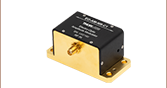
T1G
Shown with
Included OSMT
Coaxial Cable
Application Idea
LD1100 Laser
Diode Driver
T1G Bias-T
Laser Diode
Terminals
To Function
Generator
Laser Diode
DC Current
RF Modulation Input
Modulated
Laser Diode
Output


Please Wait
| Specifications | |
|---|---|
| Frequency Range | 10 kHz to 1 GHz |
| Input Impedance | 50 Ω |
| Max DC Current | 110 mA |
| Max RF Current (RMS) | 50 mA |
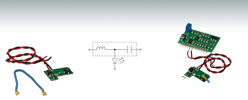
半導体レーザ用バイアスT基板T1Gは、半導体レーザのDC電源電流に変調電流を重畳するために設計されているので、これを用いて半導体レーザ出力を変調することができます。ファイバを介して情報のやり取りをする用途で便利です。
半導体レーザードライバがDC電流を設定すると、RF入力端子に交流電圧が印加されます。これによって変調電流が発生し、ご希望の振幅変調が可能になります。このバイアスT基板は、10 kHzから1 GHzまでの範囲の変調周波数に対応しています。実際の周波数範囲は、半導体レーザを取り巻くインピーダンスネットワークの特性により決定されます。 付属のOSMT(コネクタの規格)ワイヤを使って、ファンクションジェネレータをOSMT同軸コネクタに接続することができます。この同軸コネクタは、 50 Ωの特性インピーダンスを持っています。 また半導体レーザを保護するために、このデバイスにはDCをブロックするコンデンサと逆バイアス防御ダイオードが内蔵されています。
当社では、バイアスT基板T1Gの他にもレーザーコントローラの構築に適した半導体レーザードライバ、温度コントローラや評価キットなど様々な製品もご用意しています。 さらにボード型コントローラもご提供しておりますが、この製品は修整を加えなくてもラック式のシステムにそのまま組み込むことができます。
| Posted Comments: | |
Hyun-Woo Song
(posted 2024-09-24 14:42:33.44) To whom it may concern,
May I ask if you have a connector (or cable) of OSMT (T1G) for connecting (to BNC) a function generator.
Sincerely,
Hyun-Woo jpolaris
(posted 2024-10-02 05:54:50.0) Thank you for contacting Thorlabs. Unfortunately, we do not have any cables or adapters for OSMT at this time. We have reached out to you directly with some recommendations for 3rd party solutions. Our current collection of premium cables and adapters can be found at the following link: https://www.thorlabs.com/newgrouppage9.cfm?objectgroup_id=9827 Joice Mathew
(posted 2020-03-10 00:23:38.89) Hi,
We have bought T1G board recently from you. how can I actually connect the OSMT connector to a standard function generator coaxial output? I am having a hard time finding an adapter to the OSMT connector. Can you source an OSMT-BNC/OSMT-SMA (or anything else) adapter or help me to find one, please?
Thanks,
Joice. YLohia
(posted 2020-03-10 03:35:46.0) Hi Joice, thank you for contacting Thorlabs. We suggest using the 1064391-1 adapter from Tyco Electronics. This is an OSMT to SMA cable. Once converted to SMA, you can use the T4289 adapter to use with a function generator coax out port. Young Zeng
(posted 2019-12-27 10:15:38.543) Hi, I am interesting of buying the T1G unit, could you provide me with the inductance and capacitance of the bias-T, so I can run simulation beforehand to see if my RF source is sufficient for the modulation.
Regards
Young asundararaj
(posted 2019-12-27 11:51:14.0) Thank you for contacting Thorlabs. Unfortunately, this is not something that we can provide as it is considered as proprietary information. julien.schiellein
(posted 2018-07-25 08:45:57.557) Hi,
I bought several of these T1G boards. They are very convenient for testing.
However, one major drawback is the fact that the ground of the RF signal is also directly connected to what is identify as DC negative...
In the case of Anode Grounded Laser, the case of the laser is connected to the Anode of the laser, which is connected to the DC Positive of the Board...
So if you attach your laser to some case which is also holding your RF connector, you will have a short circuit between DC positive and DC negative.
This is not destructive, but it prevent the laser to work...
Do you have any plan to fixe this issue?
Best regards YLohia
(posted 2018-07-30 10:39:37.0) Hello, thank you for contacting Thorlabs. When using laser diodes that are Anode Grounded, you need to either physically isolate the TO-can from the power supply ground (usually through Earth ground) or use a power supply that is isolated from earth ground (for e.g., a linear supply). Another option is wiring the laser backwards. Doing so will make the orientation of the protection diode incorrect, which will then need to be removed from the circuit (leaving the laser diode exposed to reverse currents). lslatte2
(posted 2017-08-18 11:42:14.377) Hi, I was wondering if I could have the board dimensions? I need it to fit in a small space. In addition, is there any chance it could be made with a higher dc current? Thanks in advance. tfrisch
(posted 2017-09-13 04:54:23.0) Hello, thank you for contacting Thorlabs. The overall board dimensions are 0.870” x 0.600”, and we are working on a drawing to post as well. hz13g13
(posted 2017-02-06 06:23:27.02) Hi, I already have a thorlabs LDC205C benchtop driver, I wonder if I can connect the output from the laser driver to the T1G bias-T ? Could you please provide me with instructions?
Can you source an OSMT-BNC adapter or sell me one, please? Thanks tfrisch
(posted 2017-02-17 01:39:27.0) Hello, thank you for contacting Thorlabs. Both the DC and AC inputs of the bias T require a voltage as described in chapter 3 of the manual. I will reach out to you with more details regarding this and the adapter. mitch
(posted 2016-09-04 08:13:25.437) Hi, I have bought several of these boards from you but the OSMT connector is the rarest connector on earth, it seems! I can't find an adapter anywhere. What coax cable are you using so that I can buy my own SMA plug and use it on one end, instead? Can you source an OSMT-SMA (or anything else, really) adapter or sell me one, please? Thanks tfrisch
(posted 2016-09-07 01:40:33.0) Hello, thank you for contacting Thorlabs. I will reach out to you directly about the cable you need. mitch
(posted 2016-08-09 06:42:47.703) Hi, would it be possible to tell me what the value of the capacitor is? I see the inductor looks like 0.22uH. I would like to sun some simulations to see how well this bias-t will work for me. Thanks jlow
(posted 2016-08-15 09:21:48.0) Response from Jeremy at Thorlabs: We will contact you directly about this information. |