 Products Home / 半導体レーザ用電流コントローラ(LDドライバ)、温度コントローラ、LDマウント / 組み込み用半導体レーザー(LD)ドライバー/コントローラー / 組み込み用半導体レーザドライバー、アナログ変調
組み込み用半導体レーザドライバー、アナログ変調
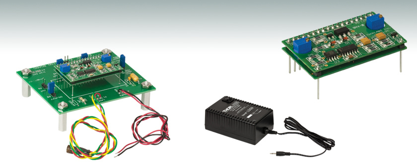
- 100 mA APC Diode Laser Driver, DC to 10 kHz Modulation
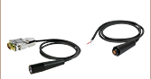
- Evaluation Kit, Pre-Wired for Laser Pin Style A
- 9 VDC Power Supply
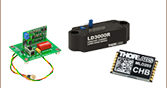
EK2000
LDS9 Power Supply
Sold Separately
LDS9
Power Supply
LD2000R
2" x 1.3" x 1/2"
A Pin Configuration

Please Wait

LD2000R、EK2000の評価キットの特長
- 定光出力モード:20 μA~125 μA
- レーザ駆動電流:0~100 mA
- EK2000はLED駆動に適した製品
- 高安定レーザ制御
- 基板上のトリムポットで、レーザ出力と電流リミット制御用
- 半導体保護用のスロースタート
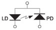
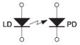
LD2000Rは高安定な半導体レーザ用電流電源で、レーザ部がアノードコモン、モニタ用フォトダイオード部がカソードコモンの半導体レーザにご使用いただけます。ドライバは自動出力制御(APC)モードで動作し、フィードバック用に半導体レーザ内蔵のモニタ用フォトダイオードを利用します。基板上のトリムポットは、レーザ出力と電流リミットを制御します。これらの機能は2つとも外部電圧電源でも制御できます。最大駆動電流が100 mAまでの半導体レーザと、20 μA~2 mAの電流のフォトダイオードなどに幅広く対応します。また外部入力端子があり、レーザ出力の変調を必要とするピンスタイルAの用途に対応できます(レーザ部がアノードコモン、フォトダイオード部がカソードコモン)。
EK2000半導体レーザードライバの評価キットによって、カスタム仕様のPCBや拡張用のカスタム配線を準備することなく、半導体レーザとDC電源をLD2000Rに簡単にセットアップすることができます。すべてのLD2000Rは、簡単で便利なコネクタ接続を採用しています。
対応するピンスタイル(スタイルAの配線の場合):
| PIN Style A | PIN Style D | PIN Style F* |
|---|---|---|
 |  |  *LD2000R のみ対応 |
| Item # | LD2000R | EK2000 |
|---|---|---|
| Current Output | ||
| Limit Current Control | Trimpot or External Analog Voltage | |
| Limit Current Range | 0 to 100 mA | |
| Limit Accuracy | ±1% | |
| Compliance Voltage | (V+/2) - ILIMIT * 5 | |
| Power Output | ||
| Photodiode Current Control | Trimpot or External Analog Voltage | |
| Photodiode Current Range | 20 to 125 μA | |
| Long Term Drift (24 hours) | <0.1% | |
| Temperature Coefficient | <100 ppm/ °C | |
| Analog Bandwidth | ||
| 3dB Bandwidth (Nominal) | 10 kHz (Actual Bandwidth is Laser Dependent) | |
| Power Supply | ||
| Supply Voltage (V+) | 8 to 12 VDC | |
| Supply Current | 30 mA Plus Laser Current | |
| General | ||
| Operating Temperature | 0 to 40 °C | -20 to 60 °C |
| Storage Temperature | 0 to 70 °C | -65 to 150 °C |
LD2000 ピン配置
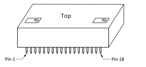
| Pin | Signal | Description |
|---|---|---|
| 1 | CX1 | These pins are provided for connecting an external capacitor to the control loop integrator to extend the integrator time constant. This may necessary to get maximum bandwidth when using TTL modulation. Connect the positive terminal of the cap to CX2. |
| 2 | CX2 | |
| 3 | Analog Modulation | This pin is used with an external voltage signal source to provide analog modulation. The transfer function (referenced to the photodiode current) is -50μA/V (see note 1) with 0V being the laser completely on. The laser output decreases as this voltage increases with the laser being completely off at 2.5V. Connect this pin to ground when not using the analog modulation. |
| 4 | Slow Start | This output pin is high during the start up period and goes low when the laser is enabled. It can be used as a LASER EMISSION indicator. An external capacitor can be connected from this pin to ground to extend the slow start delay time. Note: this output will not drive an LED directly and must be buffered (contact the factory for more details). |
| 5 | PD Current Trimpot | This pin is connected to the wiper of the on-board PD Current Trimpot. Connect this pin to the PD Current Setpoint to control the photodiode current with the on-board trimpot. |
| 6 | PD Current Setpoint | This pin controls the PD Current according to a transfer function of 50μA/V with 0V being the laser is completely off (0 photodiode current). The laser output increases as this voltage increases. |
| 7 | REF Out | This is a buffered 2.5V voltage reference. |
| 8 | PD AMP Out | This is an analog voltage proportional to the photodiode current and referenced to one half the supply voltage. |
| 9 | +V | Positive supply voltage (+8 to +12VDC). |
| 10 | Ground | Power supply common. |
| 11 | LD A/PD K | Common laser diode anode, photodiode cathode. |
| 12 | PD A | Photodiode anode. |
| 13 | LD K | Laser diode cathode. |
| 14 | Limit Setpoint | This voltage determines the maximum laser drive current according to the transfer function 46mA/V. |
| 15 | Limit Trimpot | This is connected to the wiper of the Limit Current trimpot. Connect this to the Limit Setpoint pin to use the on-board trimpot to set the current limit. |
| 16 | Not Used | This must be tied to ground to operate the laser. |
| 17 | On/Off | This pin is used to externally turn the laser on and off through the slow start circuit and to set the low voltage dropout point. It has an internal 20kΩ resistor to ground. Connect a 15KΩ resistor to the power supply voltage to set the dropout voltage to 4.5V. |
| 18 | Limit Out | This is an output voltage proportional to the limit current with a transfer function of 40mA/V. Use this pin to assist in setting the laser current limit. |
Click to Enlarge
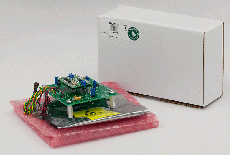
EK2000 Packaging

Smart Pack
- Reduce Weight of Packaging
- Increase Usage of Recyclable Materials
- Improve Packing Integrity
- Decrease Shipping Costs
Thorlabs' Smart Pack Initiative is aimed at minimizing waste while providing adequate protection for our products. By eliminating any unnecessary packaging, implementing design changes, and utilizing eco-friendly materials, this initiative seeks to reduce the environmental impact of our product packaging.
The updated EK2000 packaging primarily consists of recycled paper and cardboard and weighs 21.84% less than the original packaging. This weight change results in a 1.35 kg reduction in travel-based CO2 emissions per year, based on typical product sales.
As we move through our product line, we will indicate re-engineered, eco-friendly packaging with our Smart Pack logo, which can be seen above.
| Posted Comments: | |
luis.marin
(posted 2017-07-03 13:36:22.14) I need to connect style D to this driver, suggestions please... tfrisch
(posted 2017-08-03 04:47:59.0) Hello, thank you for contacting Thorlabs. This evaluation kit is compatible with style D. The floating PD cathode would be tied to ground. I will reach out to you directly to discuss this. pt_tanyingjie
(posted 2013-07-21 21:26:31.25) May i know which type of OEM driver i could use to drive LP520-SF15, which is PIN code 9E? cdaly
(posted 2013-08-02 10:20:00.0) Response from Chris at Thorlabs: Thank you for using our feedback tool. Any source which provide 180mA at the operating voltage of 7.5V should be sufficient. Pin code is only really going to affect those mounts which already have pre-wired sockets for the diode. For the LP520-SF15, I would suggest using the IP250-BV, which despite its description can be used for diodes other than blue ones. jlow
(posted 2012-09-13 12:03:00.0) Response from Jeremy at Thorlabs: It seems that the website wasn't updated to reflect the manual. We are updating the website now to fix this error. Thank you for bringing this to our attention. For your application of 25kHz with a Style A laser diode, maybe the IP500 could work for you? The bandwidth for that is DC to 50kHz. I will contact you directly to discuss about your application further. bernard.wenger
(posted 2012-09-11 05:57:42.0) In the specs on the web page the analog bandwidth is 30 kHZ, however in the datasheet this is only 10 kHz. I need a 25 kHz modulation, will it work? kalun
(posted 2011-01-12 14:19:54.0) I would like to built a fiber link using EK2000, Pigtailed Laser Diodes, Single Mode Fiber and speaker. I have questions on the modulation signal to the P10 of EK2000. Does it only accept 0-2.5V signal? If I have a mp3 player, how can I input this signal to the EK2000? Thorlabs
(posted 2010-09-08 18:50:58.0) Response from Javier at Thorlabs to bpetrig: the LD2000 is not designed to drive C type laser diodes. It will only work with the styles A, B, and D. I would recommend using the LD1101 for C type diodes:
http://www.thorlabs.de/NewGroupPage9.cfm?ObjectGroup_ID=1364&pn=LD1100&CFID=2724616&CFTOKEN=52976594
The main advantage of the LD2000 over the LD1101 is that it features an external control input for modulation up to ~30 kHz. bpetrig
(posted 2010-09-08 14:29:33.0) I am wondering if the LD2000 can be used to drive a "Style C" type laser, such as the laser
P/N DL7140-201S, in automatic power control mode?
What advantage(s) does the LD2000 laser driver offer compared to the LD1100? |
半導体レーザーコントローラーセレクションガイド
下の表は、当社の半導体レーザ用コントローラおよびデュアル半導体レーザ/温度コントローラの主な仕様の一覧です。詳しい内容や仕様について、またはご注文の際には表内の型番をクリックしてご確認ください。
| Current Controllers | ||||||
|---|---|---|---|---|---|---|
| Item # | Drive Current | Compliance Voltage | Constant Current | Constant Power | Modulation | Package |
| LDC200CV | 20 mA | 6 V | External | Benchtop | ||
| VLDC002 | 25 mA | 5 V | - | Int/Ext | OEM | |
| LDC201CU | 100 mA | 5 V | External | Benchtop | ||
| LD2000R | 100 mA | 3.5 V | - | External | OEM | |
| EK2000 | 100 mA | 3.5 V | - | External | OEM | |
| LDC202C | 200 mA | 10 V | External | Benchtop | ||
| KLD101 | 230 mA | ≤10 V | External | K-Cube™ | ||
| IP250-BV | 250 mA | 8 Va | External | OEM | ||
| LD1100 | 250 mA | 6.5 Va | - | -- | OEM | |
| LD1101 | 250 mA | 6.5 Va | - | -- | OEM | |
| EK1101 | 250 mA | 6.5 Va | - | -- | OEM | |
| EK1102 | 250 mA | 6.5 Va | - | -- | OEM | |
| LD1255R | 250 mA | 3.3 V | - | External | OEM | |
| LDC205C | 500 mA | 10 V | External | Benchtop | ||
| IP500 | 500 mA | 3 V | External | OEM | ||
| LDC210C | 1 A | 10 V | External | Benchtop | ||
| LDC220C | 2 A | 4 V | External | Benchtop | ||
| LD3000R | 2.5 A | -- | - | External | OEM | |
| LDC240C | 4 A | 5 V | External | Benchtop | ||
| LDC4005 | 5 A | 12 V | Int/Ext | Benchtop | ||
| LDC4020 | 20 A | 11 V | Int/Ext | Benchtop | ||
| Dual Temperature and Current Controllers | |||||||
|---|---|---|---|---|---|---|---|
| Item # | Drive Current | Compliance Voltage | TEC Power (Max) | Constant Current | Constant Power | Modulation | Package |
| VITC002 | 25 mA | 5 V | > 2 W | - | Int/Ext | OEM | |
| ITC102 | 200 mA | > 4 V | 12 W | Ext | OEM | ||
| ITC110 | 1 A | > 4 V | 12 W | Ext | OEM | ||
| ITC4001 | 1 A | 11 V | > 96 W | Int/Ext | Benchtop | ||
| CLD1010LPa | 1.0 A | > 8 V | > 14.1 W | Ext | Benchtop | ||
| CLD1011LPb | 1.0 A | > 8 V | > 14.1 W | Ext | Benchtop | ||
| CLD1015c | 1.5 A | > 4 V | > 14.1 W | Ext | Benchtop | ||
| ITC4002QCLd | 2 A | 17 V | > 225 W | Int/Ext | Benchtop | ||
| ITC133 | 3 A | > 4 V | 18 W | Ext | OEM | ||
| ITC4005 | 5 A | 12 V | > 225 W | Int/Ext | Benchtop | ||
| ITC4005QCLd | 5 A | 20 V | > 225 W | Int/Ext | Benchtop | ||
| ITC4020 | 20 A | 11 V | > 225 W | Int/Ext | Benchtop | ||
当社では製品組み込み用あるいはラックマウントの半導体レーザ電流&温度コントローラ(組み込み用モジュール、PRO8電流コントロールモジュール、PRO8電流&温度コントロールモジュール)もご用意しております。