 Products Home
Ø50 mm積分球

- Made of Durable, Highly Reflective Bulk Material
- 3 or 4 Input Ports and 1 Detector (Output) Port
- SM05 Threading and 30 mm Cage System Compatibility
- Post Mountable (Imperial and Metric Versions)
Application Idea
2P-DA2 Dovetail Adapter with Filter Holder Creates a Light-Tight Connection Between Two 2P3 Integrating Spheres
2P3
3 Input Ports
Highly Reflective Interior over 250 - 2500 nm


Please Wait
| Compatible Mounted Photodiodes | ||
|---|---|---|
| Sensor Type | Wavelength Range | Photodiodes |
| Si | 200 - 1100 nm | SM05PD2A SM05PD2B |
| Si | 350 - 1100 nm | SM05PD1A SM05PD1B |
| InGaAs | 800 - 1700 nm | SM05PD5A |
| 900 - 1700 nm | SM05PD4A | |
| Ge | 800 - 1800 nm | SM05PD6A |
Click to Enlarge
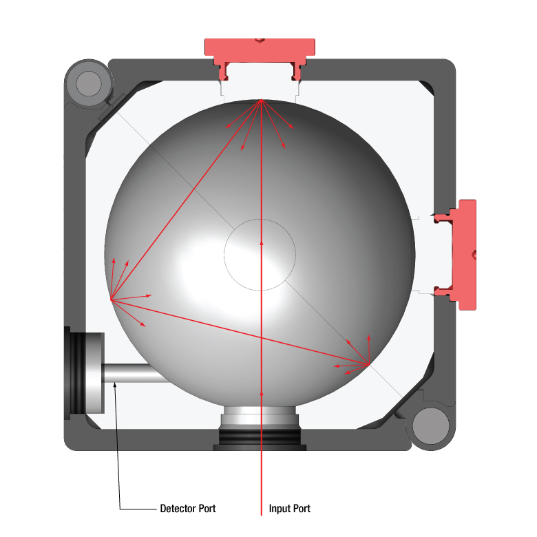
積分球の内部
Click to Enlarge
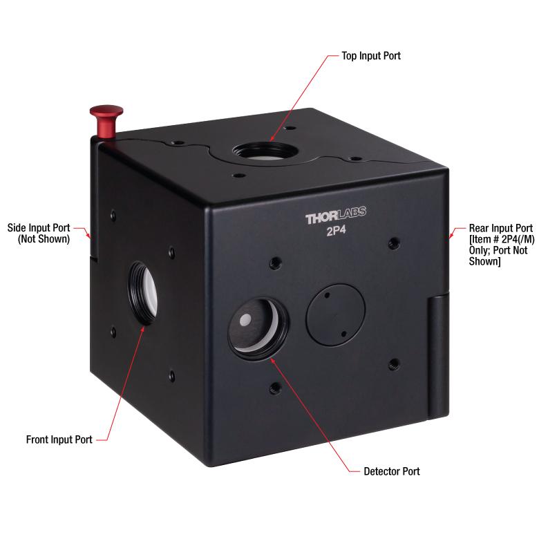
積分球筐体のポートのレイアウト
特長
- Ø50 mm積分球、黒アルマイト加工アルミニウム製筐体
- 球面の材質: 高耐久、白色、高反射率(250~2500 nm用)
- SM05ネジ付き光入射ポートが3つまたは4つ付き
- SM05ネジと窪み付きのØ3 mmディテクタ用ポートから当社のすべてのSM05PDシリーズフォトダイオードが接続可能
- 当社のSM05レンズチューブおよび30 mmケージシステムが取り付け可能
- ポスト取付け可能
- 2つの積分球を遮光連結する際に使用するアリ溝つきアダプタと薄型フィルタの保持機能を有するアダプタをご用意
- 積分球ポート用FC/PC、SMA、およびフェルールアダプタもご用意
当社の積分球は、光信号を高感度測定する汎用的なデバイスです。積分球は球面全体に渡り、複数の反射を行うことにより入射光を均一に分散します。このためレーザーパワー、光束、反射率や輝度の測定など多くの用途に適しています。
入射ポートおよびディテクタ用ポートにはSM05内ネジがついており、様々なアクセサリが取り付け可能です。入射ポートには反射コーティング付きポートプラグおよびファイバーアダプタもご用意しております(下記参照)。ディテクタ用ポートは当社のフォトダイオードSM05PDシリーズが取り付け可能です。レンズチューブシステムなどその他のSM05外ネジ付きアクセサリは、直接積分球のポートに取り付けられます。また、ディテクタ用ポートは、フォトダイオードの検出部が直接入射光に曝されないよう凹んだ位置に配置されています。
積分球の各面に付いている#4-40タップ穴には、当社の30 mmケージシステム用ケージロッドあるいはアリ溝付きアダプタ(下記参照)が取り付け可能です。アリ溝付きアダプタは、単一光子ディテクタなど、高感度の用途において拡散を増やすため、複数の積分球を遮光接続するのに便利です。底部にはポスト取り付け用のM4ネジ付き穴が付いています。
球面はPTFEベースのバルク素材で作られており、250~2500 nmの波長範囲で高い反射率を示します(詳細は「仕様」タブ参照)。また熱、湿度、高レベルの放射線に耐性があります。反射面には特定の粗さがあり、反射を散乱させるよう設計されています。溶剤を使用したクリーニングは、積分球の内側表面を損傷する可能性があるので避けてください。積分球の内側表面のクリーニングには、圧縮空気のご使用のみをお勧めしています。
当社ではご要望によりお客様が選択されたセンサと積分球で校正し、NISTやPTBトレーサブルのCertificate of Calibration(校正証明書)のご提供が可能です。詳細については、当社までお問い合わせください。
当社では異なるオプトメカニクスシステムに対応できる様々な筐体インターフェイスで構成されるモジュール式積分球もご用意しております。
| Item # | 2P3(/M) | 2P4(/M) |
|---|---|---|
| Input Ports | Three: Front, Side, and Top | Four: Front, Side, Rear, and Top |
| Sphere Diameter | 50 mm | |
| Input Port Diameter | 11.5 mm (0.45") | |
| Detector Port | Ø3 mm with SM05 (0.535"-40) Thread | |
| Typical Reflectance | > 94% at 250 nm - 2500 nm ~99% at 350 nm - 1500 nm | |
| Wavelength Range | 250 nm - 2500 nm | |
| Operating Temperature | -20 °C to 60 °C | |
| Operating Humidity | 5% to 95% | |
| Laser Damage Threshold | Pulsed: 7 J/cm2 CW: 2 kW/cm2 | |
| Weight | 350 g | |
| Dimensions | 63.0 mm x 63.0 mm x 77.0 mm (2.48" x 2.48" x 3.03") | |
Click to Enlarge
積分球の材料の反射率

Insights:積分球について
こちらのページでは積分球をセットアップに組込むときやデータ結果を分析するときに下記の考慮すべき点がご覧いただけます。
- 積分球によって放射されるUV蛍光ならびに青色蛍光
- 試料交換誤差について
このほかにも実験・実習や機器に関するヒントをまとめて掲載しています。こちらからご覧ください。
積分球によって放射されるUV蛍光ならびに青色蛍光
Click to Enlarge
図1:各波長における典型的な蛍光収量は、励起波長の強度より4桁程度低くなっています。[4]
蛍光スペクトルの収量は、積分球内で発光する蛍光の強度と励起波長の強度により決まります。収量(Yield)は積分球の内面全体で励起した蛍光量(波長に依存)を励起光の強度で割って計算します。
データご提供:Dr. Ping-Shine Shaw, Physics Laboratory, National Institute of Standards and Technology, Gaithersburg, MD 20899, USA.
積分球内面のコーティングにはポリテトラフルオロエチレン(PTFE)が使用されています。この素材は白色ですが、幅広い波長において高い、かつ平坦な反射率と、化学的不活性があることなどの理由から好まれます。
しかし、積分球はPTFEならびにPTFEよりも反射率が低い硫酸バリウムでコーティングされており、UV光を照射した場合、低量ではありますがUVならびに青色の蛍光を発光することにご留意ください。[1-3]
PTFE内の炭化水素
蛍光発光しているのはPTFE自体ではなく、UVならびに青色の蛍光の原因はPTFE内の炭化水素です。コーティングの原料には低量の炭化水素不純物が存在しており、また積分球を使用したり保管している間に汚染源によりさらに炭化水素がコーティング材に付着します。
蛍光波長域と強度
米国標準技術研究所(National Institute of Standards and Technology/NIST)の研究者がPTFEコーティング付き積分球の励起蛍光を調査しました。積分球の全蛍光量を蛍光波長と励起波長を変えて測定しています。最大蛍光量は、励起光強度より4桁程度低くなりました。
PTFEから発光するUVならびに青色の蛍光は主に200 nm~300 nmの吸収帯で励起されます。蛍光は図1のとおり250 nm~400 nmの波長範囲で発光します。励起波長を長波長側にすることにより、短い波長で発光する蛍光量が少なくなり、蛍光スペクトルの形状が変動することが示されています
PTFE内の炭化水素のレベルが高くなると、蛍光量も多くなります。それに伴い、積分球からの出力量は吸収帯波長において少なくなります。それは、このスペクトル域においてより多くの光が吸収されるからです。[1, 3]
使用への影響
PTFEから発光するUVならびに青色蛍光は、多くの用途において影響はほとんどありません。蛍光の強度が小さく、励起されるのは主に300 nm未満の入射波長の場合だからです。この蛍光に影響される用途には、UV放射の長期に渡る測定、UV光源の校正、UV反射率標準の確立、UVリモートセンシングの実施などがあります。
蛍光の影響の最小化
蛍光レベルの最小化ならびに安定化のためには、積分球をガソリン・ディーゼルエンジンの排気や、ナフタレン・トルレンなどの溶剤を含めあらゆる炭化水素源から隔離することが必要です。また、炭化水素による汚染は最小化または減少することはできますが、完全に除去できないことにご留意ください。[1]
炭化水素に曝される履歴は積分球ごとに異なるため、個別の積分球における入射光への応答性を予測することはできません。蛍光により、用途への悪影響があった場合には、積分球の校正をお勧めいたします。下記[4]では、校正に必要な光源(対象の波長にわたってスペクトルがよく知られている重水素ランプやシンクロトロン放射)、モノクロメータ、ディテクタ、積分球と、その手順について説明しています。
参考文献
[1] Ping-Shine Shaw, Zhigang Li, Uwe Arp, and Keith R. Lykke, "Ultraviolet characterization of integrating spheres," Appl.Opt. 46, 5119-5128 (2007).
[2] Jan Valenta, "Photoluminescence of the integrating sphere walls, its influence on the absolute quantum yield measurements and correction methods," AIP Advances 8, 102123 (2018).
[3] Robert D. Saunders and William R. Ott, "Spectral irradiance measurements: effect of UV-produced fluorescence in integrating spheres," Appl. Opt. 15, 827-828 (1976).
[4] Ping-Shine Shaw, Uwe Arp, and Keith R. Lykke, "Measurement of the ultraviolet-induced fluorescence yield from integrating spheres," Metrologia 46, S191 - S196 (2009).
最終更新日:2019年12月4日
試料交換誤差について


Click to Enlarge
図2:拡散試料の透過率と反射率を上記のように測定することによって、試料交換誤差に起因する試料スペクトル歪みがもたらされる可能性があります。問題は基準試料と測定したい試料測定時の、試料領域の反射率が異なることです。
Click to Enlarge
図3:上の実験構成では、積分球内の条件が基準試料測定時と測定したい試料測定時で同じのため、試料交換誤差の影響は受けません。基準試料測定時、光は(R)に沿って通り、(S)に沿っては通りません。反対に測定したい試料測定時、光は(S)に沿って通り、(R)に沿っては通りません。
積分球を使用することにより光学試料の透過ならびに拡散反射スペクトルの絶対値が測定できます。これらのスペクトルは、測定したい試料と基準とする試料の両方のスペクトルを測定することによって求められます。
基準試料の測定は、照射光源のスペクトルを知る上で必要です。基準試料のスキャンで得られた値により、測定したい試料の測定値から光源のスペクトル測定値を差し引くことができます。
光源の基準測定は、透過率データの場合、試料を配置せずに測定し、反射率測定の場合には高反射の基準試料を置き、測定します。
この試料測定や基準試料測定時において試料交換誤差が生じた場合、この誤差の影響がない実験手法でない限り、補正された試料スペクトルの確度に悪影響を及ぼす場合があります。
試料交換誤差をもたらす条件
積分球の光学性能は、内面の各位置での反射率に依存します。透過スペクトルや拡散反射スペクトル測定時、積分球の内面の一部分に試料を置きます(図2)。しかしそのような内面の一部が変化することにより、積分球の性能が変動します。
試料交換誤差は、測定手順の中で、積分球内の試料をほかの試料に交換することがあるときに懸念されます。例えば、拡散反射を測定しているとき(図2下)、最初の測定は基準試料を積分球内に取り付けて実施するとします。次にこの試料を取り外して測定したい試料に交換し、2回目の測定を行います。そして両方のデータセットを利用して、試料の補正拡散反射率(絶対値)を求めます。
この手順では、試料スペクトルに歪みが生じます。測定したい試料と基準試料の吸収ならびに散乱特性が異なるため、これらを交換することで積分球内の試料面部分の反射率が変わってきます。2つの測定において積分球の平均反射率が変わってくるため、基準試料と測定したい試料には完全な互換性がありません。
解決策1:測定したい試料と基準試料を同時に取付ける
試料交換時の誤差を回避する1つの実験手法は、測定したい試料と基準試料を同時に積分球内に取付け、測定データを取得することです。この手法では、2つの試料を追加ポートとして取り付けられる大きさの積分球が必要です。
光源は積分球の外側に配置し、測定したい試料と基準試料の両方を順次測定します。試料からの正反射、あるいは透過ビームは、積分球の外に誘導されているため、拡散光のみが検知されます。積分球の内面(の条件)は、どちらの測定でも同じのため、試料交換時の誤差の懸念はありません。
解決策2:試料用ポートならびに基準ポートから測定する
測定したい試料と基準試料が積分球内に同時に取付けられない場合、試料の交換が発生します。交換が必要な場合には、下記[1]で説明する手順で試料交換時の誤差を取り除くことができます。
この手順では合計で4回の測定が必要です。基準試料を設置時、2つの異なるポートから測定を行います。1回目の測定では基準試料が視野内にある方向から測定し、2回目の測定では試料が視野内に無い方向から測定します。その後測定したい試料に交換し、同様の測定を繰り返します。これらの測定値を利用して下記[1]に説明する計算をすることにより、試料交換時の誤差は取り除かれます。
参考文献
[1] Luka Vidovic and Boris Majaron, "Elimination of single-beam substitution error in diffuse reflectance measurements using an integrating sphere," J. Biomed.Opt. 19, 027006 (2014).
最終更新日:2019年12月4日
| Posted Comments: | |
Jan Schröter
(posted 2025-07-09 06:04:16.78) Hello, I'm trying to use the sphere to measure power while having aditional ports for spectrum etc.
I'd like to use a Power Meter Interface PM101. Which sensor would you recommend? hchow
(posted 2025-07-10 05:08:47.0) Dear Mr. Schröter, thank you for your feedback. We actually offer specials where you can pick and choose a suitable SM05-threaded mounted photodiode of your choice, after which, we calibrate the 2P3/4 together with the photodiode. We will then add a SMA to D-Sub 9 connector where the calibration data is stored on a EEPROM chip in the connector. You can then use this special with any of our power meter consoles/interfaces. In any case, I will personally reach out to you to provide solutions. user
(posted 2024-10-22 10:00:52.953) Hello! We would like to use the integrating sphere as a uniform light source for a mobile camera characterization. Our camera sensor is around 8-9 mm diameter. Could some accessories be used to add to the detector port of the sphere? Thanks! hchow
(posted 2024-10-23 05:21:56.0) Dear User, thank you for your feedback. I will personally reach out to you to provide viable solutions. Thank you. user
(posted 2024-03-15 08:31:50.59) Could these integrating spheres be used for illumination? We would like to use the 2P4 to create a uniform light source for camera sensor characterization. dpossin
(posted 2024-03-18 03:12:35.0) Dear Frank,
Thank you for your feedback. Yes the integrating spheres can be used for creating uniform light sources. Please note that the multiple inner reflections leads to attenuation of the output signal. The attenuation can be roughly estimated by calculating the ratio between the inner sphere area and the area of the output aperture. I am reaching out to you in order to provide further support. James Casey
(posted 2024-02-21 10:44:06.077) Is there a way to order two 8-32 tapped mounting plugs for the 2P4 integrating sphere? The plug I currently have has stripped threads, so I would like to get two replacements.
Thank you,
James Casey
Dow Chemical
james.casey@dow.com fmortaheb
(posted 2024-02-23 06:36:51.0) Thank you very much for contacting us. We can offer you the replacement. We'll reach out to you directly to provide you with a quote. Huiqin Zhang
(posted 2024-01-23 17:40:23.0) Hi, I am currently using reflectance mode in 2P4/M. Is there a way or any adapter to put the sample closer to the inner sphere? My sample is a large whiteboard and cannot be placed inside the sphere. However, when putting it outside of the outter sphere, there is a lot of reflected and scattered power lost at the thickness of the sphere and the measurement is inaccurate. Is there any recommended setups? Thanks. hkarpenko
(posted 2024-01-30 11:29:42.0) Dear Huiqin,
thank you for your feedback. The available adapters we currently offer, can be seen on the webpage. To select the suitable one for your application and discuss your application in detail, I will contact you directly. Robert Hlavac
(posted 2023-09-08 11:02:20.51) Hello,
Is there any way to clean the inside of the sphere without damaging it? In the description it is written not to use solvents only compressed air, but during my measurements some degradation of sample may have caused some adsorption on the inside of the sphere, and i dont think compressed air will be sufficient. Is there any other way ?
Thank you
Robert hchow
(posted 2023-09-08 09:16:16.0) Dear Mr. Hlavac, thank you for the feedback. Depending on the severity of the spill inside the integrating sphere, the performance of the integrating sphere might not be optimal. That being said, if you have spilled some solvent inside the sphere and it stains the sides, there isn't much else we can do. Wiping the internal cavity of the sphere with any inorganic solvent will most likely damage the sensitive white polymer coating even further. In any case, I will personally reach out to you to see how we can solve this problem for you. Thank you. Aparajita Naik
(posted 2023-06-27 11:30:43.7) Hi,
Is there a way to use the 2P3 integrating sphere in reflectance mode. Also from drawings I understand that there is distance of about 6mm. Will placement of samples outside the sphere affect the accuracy. hchow
(posted 2023-06-29 11:15:20.0) Dear Mr. Naik, thank you for your feedback. The 2P3 integrating sphere can indeed be used in reflectance mode. The distance between the inner round cavity of the sphere to the outer surface of the cube shape of the product is roughly 3.5 mm. The samples should be placed as near as possible to one of the ports of the sphere in order to guarantee the reflected light from the sample is kept within integrating sphere. user
(posted 2023-02-22 16:51:00.04) Hi, what is the name of the high reflectivity coating on these integrating spheres, is it Spectraflect? hchow
(posted 2023-02-23 06:44:08.0) Dear Customer, the internal coating within the cavity of the integrating sphere is made from PTFE or Polytetrafluoroethylene. Taras Lisouski
(posted 2022-10-04 17:27:50.663) Hello,
The drawings presented in the Tab "Insights" show that the samples are placed extremely close to the circumference of the integrating sphere, almost on the inner surface of the sphere. At the same time, it looks that the sample is bigger than the port opening. We understand that this is a schematic drawing. Below are our questions:
1. How can the sample be placed this way in practice? In case for 1" or 1/2" flat sample, for example.
2. We understand that the distance between the inner circumference of the sphere and the external surface of the port is about 6 mm. Will this distance influence the accuracy of measurements? dpossin
(posted 2022-10-05 08:26:23.0) Dear Taras,
Thank you for your feedback. The 2P4 can be opened completely in order to place an sample inside. Regarding your other question I reach out to you directly. Rommel Ignacio
(posted 2022-08-11 15:44:29.147) may we know what is the replacement for IS200-4 Sphere? Kindly send us a quote for 3pcs. T hkarpenko
(posted 2022-08-11 11:13:33.0) Dear Rommel,
thank you very much for your feedback. We have no direct replacement for the IS200-4, since we have changed the design for our integrating spheres. The most similar sphere is the 2p4 with 4 ports.
I will contact you directly to discuss this with you further. user
(posted 2021-12-03 02:05:31.143) Hi, I want to combine light pulses emitted from several (2-3) Xe-sources into one optical fiber. Can integrating spheres such as 2P3 be used in this kind of application ? Best regards, Jukka mdiekmann
(posted 2021-12-07 11:07:44.0) Hello - Thank you for your interest in this product. We will contact you directly to discuss your applciation. Ermanno Bernasconi
(posted 2021-07-14 10:21:55.28) Good MKiess
(posted 2021-07-16 11:05:41.0) Dear Ermanno, Thank you very much for this feedback. We are glad that you like our product. It is always nice to hear when you are satisfied with the quality and application of our products. Thank you very much thomas pongetti
(posted 2021-05-25 12:19:55.72) Do you carry or customize gold integrating spheres that operate from 6 to 10 micrometers? soswald
(posted 2021-05-28 05:16:09.0) Dear Thomas,
thank you for your feedback. Gold-coated integrating spheres are currently not part of our catalogue, but we plan to add them in the future, hopefully next year.
For a short term solution we could offer an uncalibrated VML10T0 added to S180C to measure the spectral range from 6 to 10 microns.
Since you prefer not to be contacted, please contact your local tech support team for further information. Huabin Yu
(posted 2020-11-11 13:13:34.023) I notice that there are sphere material reflectance profiles of the Integrating sphere (IS200-4) above 250 nm. However, I want to know the sphere material reflectance between 230nm to 250 nm. wskopalik
(posted 2020-11-11 10:31:54.0) Dear Huabin,
Thank you very much for your inquiry.
Unfortunately we have no data showing the reflectivity below 250nm. At 250nm the reflectivity has already dropped to about 95%. For shorter wavelengths the reflectivity of the sintered PTFE material will drop even further.
I will contact you directly to discuss your application in more detail. Paweł Hermanowicz
(posted 2020-10-21 08:47:13.48) I have received a IS236A-4 sphere with a mounted photodiode detector stuck inside the SM05 tube. When I tried to remove it, the photodiode did not yield, instead its leg broke or at least deatached form the SMA connector, so that it no longer works. Thorlabs declined to replace it. dpossin
(posted 2020-10-23 08:35:13.0) Dear Pawel, Thank you very much for your feedback. Sorry for the inconvenience this has caused you. We would be happy to repair your integrating sphere. I will reach out to you in order to find an agreeable solution. Szymon Grzanka
(posted 2020-10-20 13:14:38.587) Hello,
I would like to buy an integrating sphere with four ports and a mounted photodiode. I don't know what device (power meter) can be connected to the photodiode to be able to measure optical power. One of the remaining ports will have an optical fiber installed and a spectrometer will be connected to it. The whole is to measure the LIV characteristics.
Thank you in advance for your help.
Best wishes,
Szymon Grzanka dpossin
(posted 2020-10-21 10:26:20.0) Dear Szymon, Thank you for your feedback. I am reaching out to you in order to discuss available options with you. user
(posted 2019-12-16 15:52:36.14) Hi,
I'm interested in purchasing a IS210C that is calibrated. It says on the site: "For our integrating spheres we offer a calibration service upon request."
What does this calibration involve? Ideally, I'd like to get a power reading into Matlab or Labview while using other ports for a Spec Analyzer. Do I need other accessories for a digital power reading?
Would the link below with S145C integrating sphere be a better alternative? I'd lose the extra ports.
https://www.thorlabs.com/newgrouppage9.cfm?objectgroup_id=4688
Thanks,
-Ashok nreusch
(posted 2019-12-18 07:22:14.0) This is a response from Nicola at Thorlabs. Thank you for your inquiry. We can offer a calibrated version of our integrating spheres. Before calibrating the sphere, we need to check which port configuration you would like to use. During the calibration, we determine the wavelength-dependent responsivity of the photodiode. The photodiode will deliver a photocurrent and the optical power needs to be recalculated based on the calibrated responsivity data. In order to be able to directly use the power reading in terms of Watts in Matlab or Labview, you need to implement the responsivity data into your program code. As alternative, we can also offer a customization in which the photodiode is read out via our C-type connector similar to S145C. You can then use a powermeter console like e.g. PM100USB to convert and read out the optical power in Watts in Matlab or Labview. I will contact you directly to discuss your port configuration and send you a quotation. user
(posted 2019-12-13 06:11:48.157) Dear Thorlabs Team,
I would like to purchase an integrating sphere. At now, I just need three ports, but in the future, I may need the fourth. I would like to ask about the drawbacks of the fourth port in the 2 inches integrating sphere. Have you noticed any significant drop in the attenuation level of the sphere?
Best regards,
Pawel Hermanowicz
Jagiellonian University,
Krakow, Poland MKiess
(posted 2019-12-13 08:23:03.0) This is a response from Michael at Thorlabs. Thank you very much for your inquiry! You can use an Integrated Sphere with four ports (like IS200-4) and close the unused port with an SM05CP2C end cap. This end cap has the same surface as the integrating sphere itself. If you want to use the port after all, you can simply unscrew the SM05CP2C.
If you use the Sphere correctly and prevent dirt from getting inside, you should not notice any major changes in the reflectivity of the surface. A diode itself, on the other hand, should be calibrated annually. Even if you change the input ports, you should recalibrate them due to the changed circumstances. Felix Köttig
(posted 2019-09-27 08:46:08.167) Dear Thorlabs support,
I was wondering if you can provide the reflectivity curve of the integrating sphere coating down to 200 nm?
Thanks and best regards,
Felix Köttig
Max Planck Institute for the Science of Light
Erlangen, Germany wskopalik
(posted 2019-10-04 11:08:16.0) This is a response from Wolfgang at Thorlabs. Thank you very much for your inquiry.
Unfortunately we have no data showing the reflectivity below 250nm. At 250nm the reflectivity has already dropped down to 95%. For shorter wavelengths the reflectivity of the sintered PTFE material will drop even further.
I will contact you directly to discuss your application in more detail. Bill Albert
(posted 2019-07-02 19:00:44.777) I am curious why the effective loss of the integrating sphere is not included in the specifications. If the Integrating Sphere has an effective power loss of 20dB between the input and output ports, the measuring sensor system has lost an effective 20dB of sensitivity. For a sphere with 30dB of loss, the effect is, of course, correspondingly greater. From a systems standpoint, I believe the information would be most helpful for determining the required sensor to mate the sphere with. MKiess
(posted 2019-07-08 10:02:51.0) This is a response from Michael at Thorlabs. Thank you very much for inquiry.
The effective loss depends on various factors, such as the wavelength of the light, the area of the sensor, and the ports which are used. The theoretical attenuation can be calculated with the wavelength-dependent reflection of the PTFE surface, as shown in the specifications on the webpage. With these values, the sphere surface of approximately 8100mm^2 and the aperture of the outputs, the attenuation can be estimated. In addition there is a gain factor of 1.5 due to multiple reflections, which can be neglected again due to special sphere properties resulting from manufacturing. We also offer models incl. calibration service and desired sensor. I have contacted you directly to select a suitable sensor for your application and provide further assistance. benjamin.bissig
(posted 2018-01-18 15:52:36.673) Hi. Do you offer a solution to introduce (thin film on substrate) samples into the sphere? wskopalik
(posted 2018-01-19 04:44:26.0) This is a response from Wolfgang at Thorlabs. Thank you very much for your inquiry.
We don't offer a ready-to-use solution for this. The integrating spheres have however a lot of possibilities to attach mounts. You could e.g. use the SM05 threading in the ports or also the 4-40 threads which are normally used for our cage sytem.
It is important to note that the reflecting surface on the inside of the sphere must not be touched by the sample because this could change the reflectivity of the surface.
I will contact you directly to provide further assistance. hsubon
(posted 2017-05-23 20:23:18.117) The listed two InGaAs detectors for the integrating sphere IS210C, SM05PD4A and SM05PD5A, are both shown "Cathode-grounded". However, in "Speccs", IS210C shows "Anode-Grounded SM05PD4A". Please clarify which description is correct. Thanks. wskopalik
(posted 2017-05-24 11:32:18.0) This is a response from Wolfgang at Thorlabs. Thank you very much for your inquiry.
The SM05PD4A and SM05PD5A are both cathode grounded and they can both be attached to the integrating sphere IS200.
The IS210C is a bundle of an integrating sphere IS200 and an InGaAs photodiode. The photodiode in this bundle is a special anode grounded version of the SM05PD4A which used to be available as a catalog item and can now be offered as a special. It was called SM05PD4B. The housing and the photodiode in SM05PD4A and SM05PD4B are the same, only the grounding is different.
I will contact you directly to provide further assistance. huke
(posted 2016-06-13 15:32:21.163) I would like to get an estimate for the efficiency (incoupled light intensity/ outcoupled light intensity) of incoherent light for the full specified wavelength range at all ports. Is this possible? shallwig
(posted 2016-06-15 06:29:41.0) This is a response from Stefan at Thorlabs. Thank you for your inquiry. The theoretical attenuation level can be calculated from the reflection of the PTFE, the reflectivity graph can be found in the “specs” Tab, from the sphere surface which is ca. 8100mm2 and the area of the aperture light gets coupled out. The attenuation factor calculated this way allows you to estimate the efficiency. But due to some sphere specific properties (bulky parts of the sphere, joints, ports) this must be decreased by a factor of about 1.5. I have called you to discuss your application in more detail and check if a special meets your requirements. emtonita
(posted 2015-03-30 14:08:51.517) Hello! I was wondering: what is the performance of the IS200 at 180nm? I understand the sphere is supposed to work in the range of 250-2500nm at ~99% reflectivity. What is it's reflectivity at 180nm? Thank you, Erin. shallwig
(posted 2015-03-31 03:24:32.0) This is a response from Stefan at Thorlabs. Thank you very much for your inquiry. Unfortunately we have no data showing the reflectivity below 250nm . In the “Specs” Tab of the website http://www.thorlabs.de/newgrouppage9.cfm?objectgroup_id=1658&pn=IS200#6613 you can find the reflectivity plot. At 250nm the reflectivity drops down to 95% and for shorter wavelength the reflectivity of the used sintered PTFE will be less. The integrating spheres show significant absorption and fluorescence features for UV light. Any environmental contaminants strengthen this behavior. These features are more pronounced for sintered integrating spheres than pressed ones. There is no special coating for UV available.
I will contact you directly to discuss your application in more detail. patricio_romero
(posted 2015-03-17 17:29:39.497) Hello
I have a IS200-4 Sphere. In one of the caps, when i unscrew it, the Coating part stay inside the sphere, and I only get out the metal cap with the glue (souble contact) on it.
Reading the description I see that the coating is PTFE, so:
- Would the reflective part whistand forces to remove it?
- Once I remove it, would it whistand pressing it with a finger against the metal cap so it glues completely on the metal cap? (seems like only the borders make contact).
- Would a piece of parafilm work as protection to press it with my finger or it would contaminate it? If so, what should be "clean enough" to push against the reflective part to fix it in the metal cap? shallwig
(posted 2015-03-18 10:09:42.0) This is a response from Stefan at Thorlabs. Thank you very much for your inquiry and please apologize the problems you face with one of the caps of your IS200-4 integrating sphere. This should not happen that the coating part stays inside the sphere when unscrewing the cap. I will contact you directly and we will send you an exchange of the End cap (SM05CP2C). I am sorry for any inconveniences. michael-miller
(posted 2015-02-23 18:32:41.9) We have purchased an IS200-4 integrating sphere. Our application is under vacuum. If we were to partially evacuate the interior of the sphere, would we compromise the integrity of the sphere?
Thanks tschalk
(posted 2015-02-25 09:06:58.0) This is a response from Thomas at Thorlabs. Thank you very much for your inquiry. Our integrating spheres are not designed to be used in vacuum. The housing is anodized which will have a bad influence of the vacuum quality. Otherwise, there is no fundamental reason why the unit shouldn’t work in vacuum conditions. I will contact you directly to discuss your application. 1982ariel
(posted 2015-01-21 15:51:41.24) Thorlabs hello
I think that it would be better to present 3D images option of the products. The kind where you can rotate the product.
Some times I need to know if there is a thread or some other standard feature.
Ariel myanakas
(posted 2015-01-21 11:26:02.0) Response from Mike at Thorlabs: Thank you for your feedback. We will look into the possibility of adding a feature like this in the future. However, The taps, threading, and other design elements of a product can be found in the PDF drawing which can be found by clicking on the red "Docs" icon by the blue item number links. We also offer models that can be viewed and rotated by clicking on the available model files (Step, Solidworks, e-drawing) within the same "Docs" link. parispapagiorgis
(posted 2014-05-09 13:24:24.853) I would like to ask, how to clean the inner surface of the sphere, from traces of samples meausered? Are there any solvents or other ways to clean it? shallwig
(posted 2014-05-12 05:13:39.0) This is a response from Stefan at Thorlabs. Thank you very much for your inquiry. We only recommend to use air for cleaning the inner surfaces of the integrating spheres. The inner surface is made from specially sintered PTFE which provides its particular roughness and the diffusive reflection properties. Buy cleaning the surface with any solvents it is possible that the roughness get damaged hence the properties of the reflection change. If your application does not require the calibration to be maintained, then other cleaning methods would also work. I will contact you directly to discuss a solution for your application in detail. user
(posted 2013-05-03 15:47:14.22) An integrating sphere as the IS200 or the IS200-4 with 2 detector ports would be useful for applications where different dectors are required. Im my case, I need the same detector, but with different filters in front of it. Removing the dector and changing the filter is not convenient... Others applications where an infrared and visible detector could be used at the same time are also possible. tschalk
(posted 2013-05-06 11:12:00.0) This is a response from Thomas at Thorlabs. Thank you very much for your feedback. It is a very good idea to have one more port for an additional detector. I will forward this idea to our development department. tschalk
(posted 2013-05-08 01:54:00.0) This is a response from Thomas at Thorlabs. I discussed this idea with our development department and we can offer a special item. It would be great if you can contact us (Europe@thorlabs.com) to discuss your application and the details for the special. segreto
(posted 2013-04-02 15:42:27.423) The SMA Fiber Adapter Plate should be coated with the Reflective Sphere Material. cdaly
(posted 2013-04-04 10:10:00.0) Response from Chris at Thorlabs: Thank you for using the web feedback. The fiber adapter, SM05SMA, is used outside of the IS200(-4) as well, which is why it's not covered with PTFE already. We may be able to offer this as a custom and I will contact you directly to speak about this. Since you will need to calibrate the photodiode mounted in the IS200-4, this uncoated area should not affect your measurement. tschalk
(posted 2012-10-24 12:34:00.0) Response from Thomas at Thorlabs:
Thank you very much for your inquiry. The reflectance of the sphere material is wavelength dependent and about 99% from 350nm to 1500nm. The lose is caused by the reflections inside the sphere. Unfortunately there is nothing you can do against it because this is a physical characteristic of the reflectance material.
I will contact you directly to discuss this issue. a.d.v.dam
(posted 2012-10-24 06:01:24.747) The intensity of the light entering the sphere is about 10x as much as the light which comes out at the detector port. It seems that we lose 90% of the light inside the sphere, probably absorbed by the white coating. Is this possible? What can we do to actually collect all the light in the sphere?
Thanks. jvigroux
(posted 2012-10-03 08:08:00.0) A response form Julien at Thorlabs: Thank you for your inquiry! I wll try to answer your question in eth same order:
1. they are in principle compatible. you can either use a self built adapter from SMA to Dsub 9 to connect the IS236A-4 to the PM100D or we can also make a special that will directly come with a Dsub 9 connector
2. The integrating sphere can in principle accomodate the S314C. You will need for this a lens tube adapter from 1/2" to 1". In this case, the active surface of the S314C will be recessed quite far away from the surface of the shpere so that the attenuation will be at least 4 orders of magnitude
3. you can exchange the diode that is mounted in the IS236A-4 against any other 1/2" mounted photodiode.
One point that was not discussed is the calibration of the photodiode contained in the IS236A-4. In principle, we can calibrate the system diode+sphere and either deliver a diode with Dsub9 connector where the calibration values will be saved such that they can be read out by the PM100D or use the standard SMA connector and send you a document listing the responsivity values for the different wavelengths. The calibration would be of course only valid for the detector mounted into the sphere. wesam002
(posted 2012-10-03 06:27:00.0) hello,
we want to buy PM100D+ s314c+ IS236A-4 and we have the following questions
1. are the above items compatible with each other.
2. Can we use the integrating sphere with s314c.
3. how much will it cost to add InGaAs sensor to IS236A-4 along with Si sensor included and the possibility of replacing the sensors when we wish.
thanks jvigroux
(posted 2012-09-06 12:44:00.0) A response from Julien at Thorlabs: Thank you for your inquiry. We can offer additional port plugs for the integrating sphere. We will send oy a quote directly. Concerning the coating, we use the Zenith from SphereOptics. Oil is in principle not a problem for the machining of the coating provided the part s properly cleaned afterwards. It should however not be introduced into the sphere since it will modify the reflection properties of the coating. alexglenday
(posted 2012-09-05 14:45:19.0) Is it possible to purchase additional port plugs for the integrating spheres (part SM05CP2C on the shipping list)? I would like to modify the plug to make a smaller entrance hole. I assume the white reflective material in the sphere is Zenith (from SphereOptics)? There does not seem to be much information on this material online, does it have similar properties to Spectralon (from Labsphere)? Particularly, is oil contamination a significant issue? Thank you. julien
(posted 2010-05-28 04:05:29.0) A response from Julien at Thorlabs: Yes, the damage threshold for the IS236A is also 2kW/cm2 in CW mode. We will add this specification in the data sheet. bonito
(posted 2010-05-27 09:32:47.0) I am comparing general purpose integrating spheres (IS200 series) with calibrated integrating spheres used as sensors (S140C series).
In specifications of S142C appears 2 damage threshold values: 2 kW/cm2 and 7J/cm2.
In specifications of IS236A appears only 7J/cm2 as threshold damage.
Can I assume that maximum power density in IS236A is also 2kW/cm2?. Tyler
(posted 2008-03-19 07:11:41.0) Response from Tyler at Thorlabs to vlserg: Thank you for pointing out the mistake in our product description. The IS236A-4 integrating sphere has a silicon sensor. vlserg
(posted 2008-03-19 02:48:32.0) What detector type is bild-in IS236A-4: Si or Ge? |

 ズーム
ズーム| Key Specsa | ||
|---|---|---|
| Item # | 2P3(/M) | 2P4(/M) |
| Input Ports | Three: Front, Side, and Top | Four: Front, Side, Rear, and Top |
| Sphere Diameter | 50 mm | |
| Input Port Diameter | 11.5 mm (0.45") | |
| Detector Port | Ø3 mm with SM05 (0.535"-40) Thread | |
| Typical Reflectance | > 94% at 250 nm - 2500 nm ~99% at 350 nm - 1500 nm | |
- SM05ネジ付き入射ポートが3つ、あるいは4つ付き
- SM05ネジ付き出射ポートが1つ
- 筐体が簡単に開けるリリースノブ
- ポスト取付用M4タップ穴
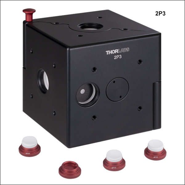
- 反射コーティング付き入射ポート用プラグが付属(各ポートに付き1個、型番2P10)
こちらの積分球には入射ポートが3つまたは4つ、そしてディテクタ用(出射)ポートが1つ付いています。入射ポートはSM05ネジ付きで、反射コーティング付きポートプラグ(付属品)またはネジ付きファイバーアダプタ(別売り、下記参照)を取り付け可能です。ディテクタ用ポートにもSM05ネジが付いており、当社のSM05PDシリーズフォトダイオードが直接取り付けられます。ポートは、入射光が直接フォトダイオードの検出部に当たらないよう窪みが付いています。

 ズーム
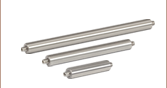
ズーム- Ø50 mm積分球間の光が漏れない接続
- アダプタの種類:薄型(型番2P-DA1)またはフィルタホールド機能付き(型番2P-DA2)
- 追加用のフィルタホルダもご用意(型番2P-DAF)
こちらのアリ溝付きアダプタは2つの積分球を光が漏れないよう接続するため、高感度測定において1つの積分球よりも拡散量を増やしたい場合などに有用です。アダプタには、アリ溝でつながっている2つの取付プレートが付いています。積分球2Pxに取り付けるには、取付プレートを分解し、それぞれを#4-40ネジ付き穴に取り付けることで、積分球面に30 mmケージシステムを取り付け可能となります。各アダプタには、8本の#4-40皿頭プラスネジ(各取付けプレートに4本)と1/16六角レンチが付属しています。アダプタを取り付けた後は、2つの積分球を右のように(2P-DA1を使用)アリ溝をスライドさせることで接続できます。
薄型アリ溝付きアダプタ2P-DA1の厚さはわずか6.2 mmのため、積分球間の距離が最小になり、スペースの節約となります。
アダプタ2P-DA2(厚さ16 mm)には、厚さ6.3 mmまでのØ25 mm~Ø25.4 mm(Ø1インチ)光学素子が取り付け可能なフィルターホルダーインサート(型番2P-DAF)が付いています。こちらは2つ目の積分球に入射される前の光にさらにフィルタ設置が必要な用途に便利です。追加用のフィルターホルダ(別売り)により複数のフィルタが簡単に交換可能です。フィルターホルダーインサート2P-DAFは、SM1内ネジ付きで、光学素子固定用の固定リングSM1RRが付属します。また、フィルタの情報が書き込める白いラベル付きです。

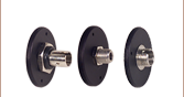
 ズーム
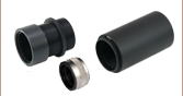
ズーム- 積分球の入射ポート用反射コーティング付きプラグ
- FC/PCまたはSMAファイバーアダプタ
- Ø2.5 mmフェルールアダプタ
- 穴なしポートプラグ(積分球に付属)
こちらのアクセサリはSM05外ネジ付きで、上記の積分球の入射ポート用の製品です。4種類ともすべて片面は、積分球と同じ反射材でできており、積分球内表面の曲率半径に合致するよう曲面形状をしています。
2P-FCおよび2P-SMAは、それぞれFC/PC(2.2 mmワイドキー)とSMAファイバーパッチケーブルを入射ポートに取り付けるためのアダプタです。フェルール用アダプタ2P-25は、ロッキングコネクタ機構無しの設計になっています。Ø2.5 mmフェルール付きのファイバーパッチケーブルに対応し、積分球を用いた測定を迅速に行うことができます。2P10は、積分球の入射ポートをブロックするためのプラグで、上記の積分球には入射ポート1個につき1つのプラグが付属します。