 Products Home
磁気脱着式ベース
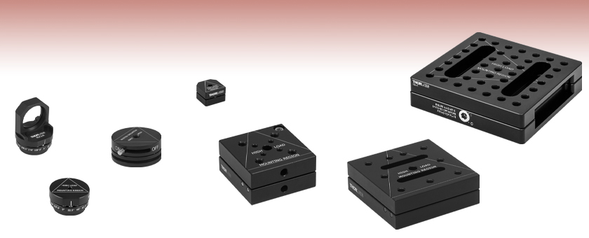
- Square and Circular Magnetic Retention Bases
- Magnetic Mounting Seats for Aluminum Breadboards
- Indexing Mounts with 22.5° Increments
- Precision Ball and V-Groove Design for High Repeatability
NX1N
Indexing Base
with Ø1" Optic Mount,
16 Positions
NX1NF
Indexing Base,
16 Positions
SB1
Locking Circular Base
KB3X3
Magnetic Base,
3" x 3"
KBM1
Lockable Kinematic Breadboard,
3.94" x 3.94"
KB2X2
Magnetic Base,
2" x 2"
MKB19
Magnetic Base 0.75" x 0.75"


Please Wait
Click to EnlargeFigure 1.1 キネマティックブレッドボード台座KBS98を使用してブレッドボードをキネマティックプラットフォームに変換できます。
特長
- 高い再現性で部品の脱着が可能
- ボールならびにV型溝が精密なアライメントを実現
- 希土類マグネットが上部と底部のベースプレートを結合
- 上部プレートと底部プレートは単体、またはセットでご提供可能
磁気脱着式キネマティックベースは、光路に取付けた部品を高い再現性で脱着する必要がある際に適しています。 当社のボールならびにV型溝設計により、上部プレートが底部プレートに高い精度で位置決めされます。 この2つのプレートは希土類マグネットの組合せにより結合しています。
セレクションガイド
| Product Image (Click to Enlarge) | 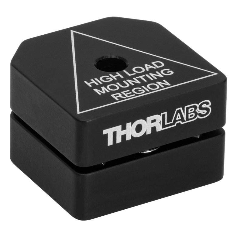 | 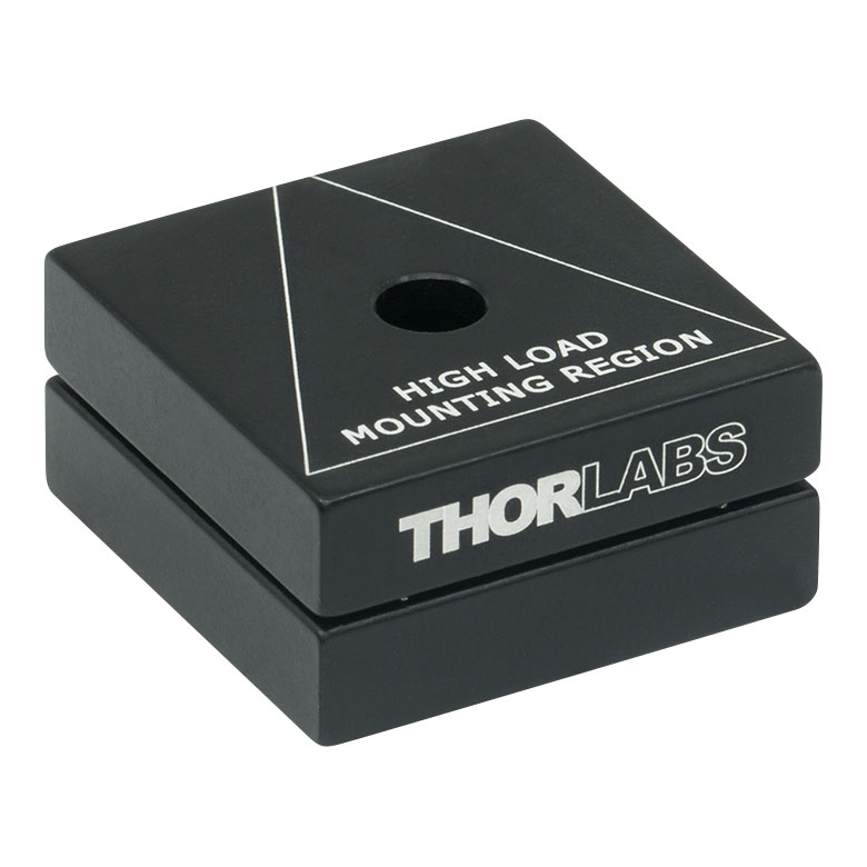 | 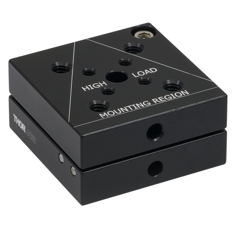 | 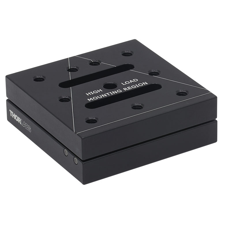 | 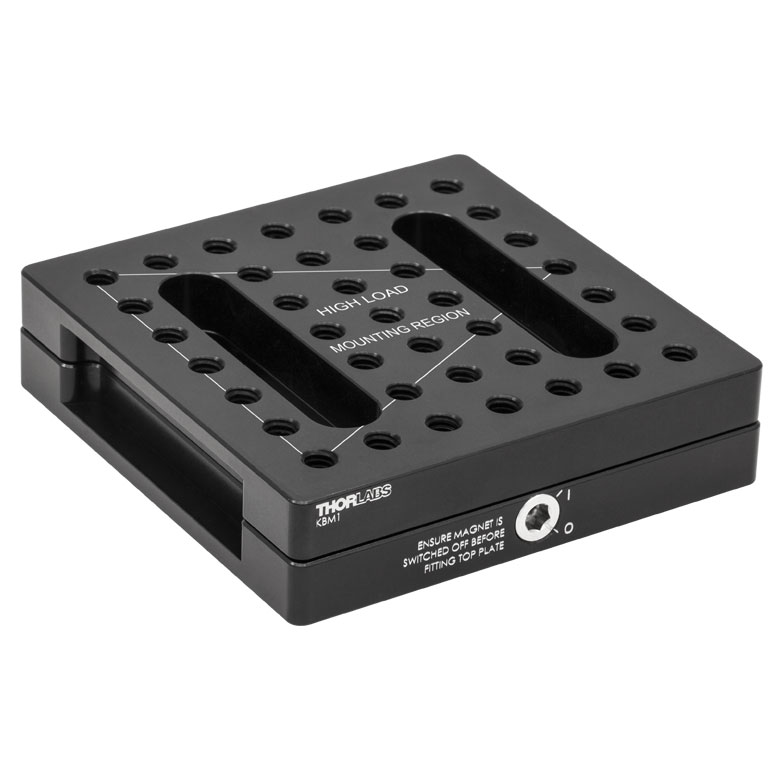 | 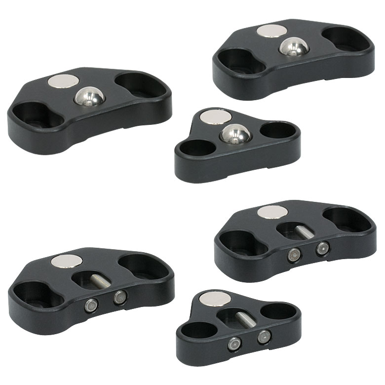 | 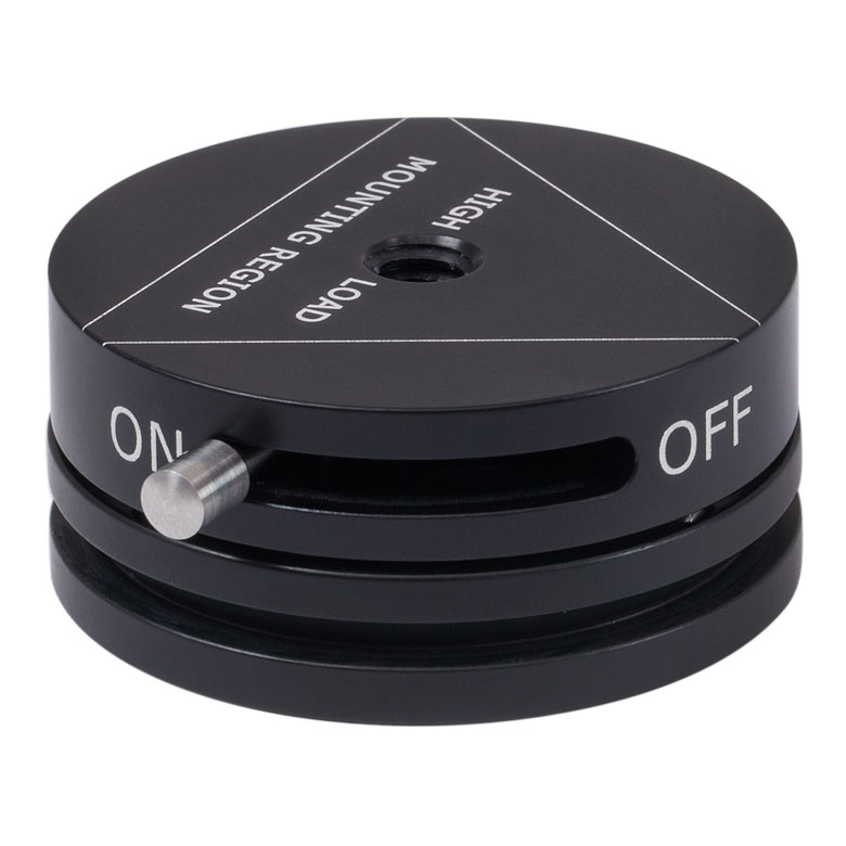 | 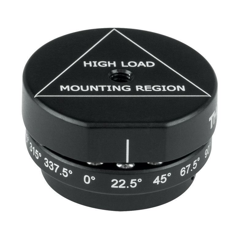 | 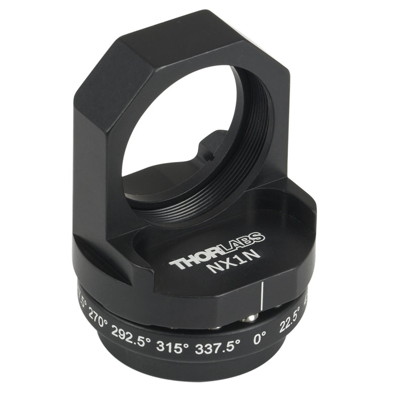 |
| Item # | MKB19 | KB1X1 (KB25/M) | KB2X2 (KB50/M) | KB3X3 (KB75/M) | KBM1 (KBM1/M) | KBS98 | SB1 (SB1/M) | NX1NF (NX1NF/M) | NX1N (NX1N/M) |
| Features | Mini-Series Compatible | Compact | Multiple Mounting Options | Multiple Mounting Options | Multiple Mounting Options, Locking Magnet | Breadboard Mounting | Locking Magnet | 16 Positions | Ø1" Optic Mount, 16 Positions |
| Tapped Holes | None | None | Four 1/4"-20 (M6) Taps Four 8-32 (M4) Taps | Nine 1/4"-20 (M6) Taps | 39 1/4"-20 (M6) Taps | N/A | 1/4"-20 (M6) Tap | 8-32 (M4) Tap | N/A |
| Counter- bores | #4 (M3) Hole | #8 (M4) Hole | 1/4" (M6) Hole | 1/4" (M6) Hole | None | 12 1/4" (M6) Slots | None | None | N/A |
| Size | 0.75" x 0.75" (19.1 mm x 19.1 mm) | 1" x 1" (25 mm x 25 mm) | 2" x 2" (50 mm x 50 mm) | 3" x 3" (75 mm x 75 mm) | 3.94" x 3.94" (100 mm x 100 mm) | N/A | Ø1.7" (Ø43 mm) | Ø1.3" (Ø33 mm) | Ø1.3" (Ø33 mm) |
The procedure used for angular repeatability testing differs depending on the size of the mount. Our Mini-Series Kinematic Base (Item # MKB19) has a unique testing procedure that is outlined below. The procedure used for the larger series bases is described afterwards.
Mini-Series Angular Repeatability Testing
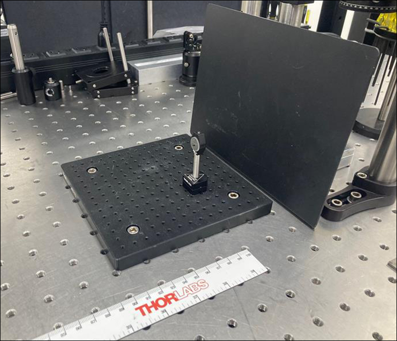
The procedure shown below illustrates the method used for determining the angular repeatability of the Mini-Series Kinematic Base. First, the bottom plate of the MKB19 kinematic base was fastened to the optical table. A Ø1/2" mirror (Item # PF05-03-P01) in a mirror mount (Item # MFM05) was attached to a 1" post (Item # MS1R) which was itself attached to the top plate of the MKB19. To ensure that only the movements of the MKB19 base were observed, the mirror, mirror mount, post and top plate were fixed together with epoxy. The top plate was then placed on top of the bottom plate. A fiber-coupler laser source (Item #s P1-630A-FC-2 and S1FC635) was collimated (Item # F110FC-633) and directed at the fixed mirror on top of the MKB19 base. The reflected beam was captured on a previous-generation BC106N-VIS beam profiler mounted 1 m away from the mirror.
Click to Enlarge
Figure 2.3 A PF05-03-P01 mirror is mounted in a MFM05 mirror mount on top of the MKB19
mini-series base.
Click to Enlarge
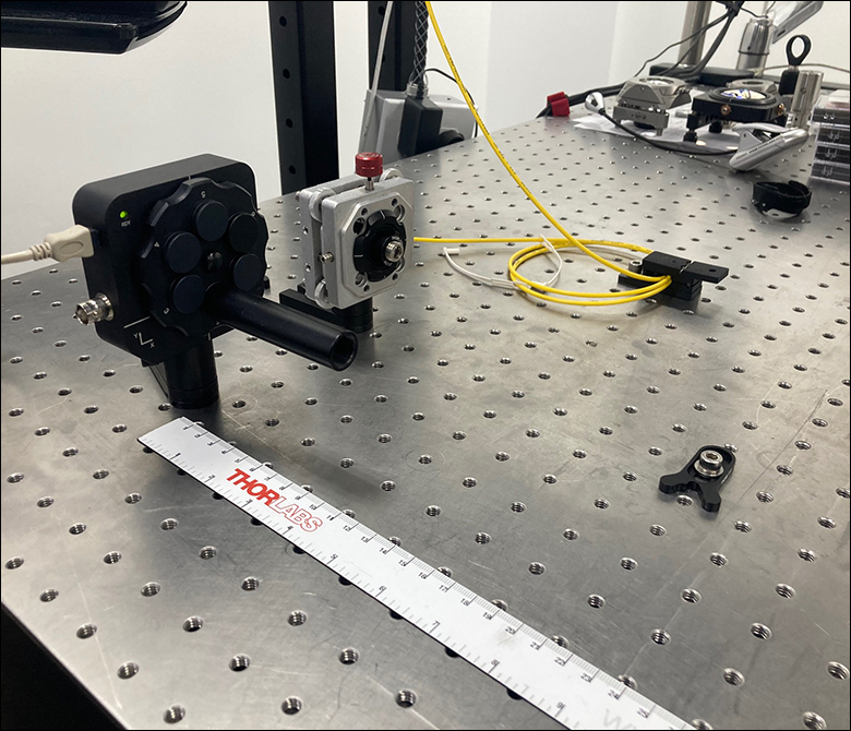
Figure 2.2 The S1FC635 source emits a 635 nm beam that is then collimated via a F110FC-633 collimation package. The reflected beam is captured on a BC106N-VIS beam profiler.
Click to Enlarge
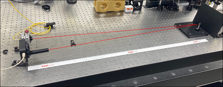
Figure 2.1 Experimental Apparatus for Repeatability
Testing with 1 m Beam Path from the PF05-03-P01 Mirror to
the BC106N-VIS Beam Profiler
Three MKB19 bases were tested for angular repeatability of position. In each case, the top plate mirror assembly was removed and replaced 50 times. The position of the reflected beam was captured on the beam profiler for each placement of the top plate. The change in position of the beam on the beam profiler was used to extrapolate the angular deviation of the mirror on the kinematic base.
The results of the measurements are presented in Table 2.4 as the absolute difference in µrad between the original position of the beam on the sensor and the position after removing and replacing the top plate of the kinematic base. The combined value takes into account both X- and Y-position measurements and represents the net distance of the deviation from the origin.
| Table 2.4 MKB19 - Summary of Results | ||||
|---|---|---|---|---|
| Dimension | Mean | Maximum | Standard Deviation | Plot |
| |ΔX| | 3.73 µrad | 11.9 µrad | 4.64 µrad |  |
| |ΔY| | 1.39 µrad | 5.80 µrad | 1.92 µrad |  |
| Combined | 4.16 µrad | 11.9 µrad | 2.82 µrad |  |
Repeatability Testing for Larger Mounts
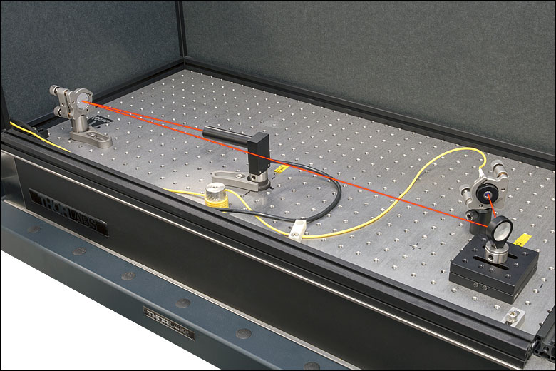
A selection of Thorlabs Kinematic Bases were tested to determine the deviation of a reflected beam attributed to removing and replacing the top plate of the base. The test setup (see Figure 2.4) consisted of an S1FC635 fiber-coupled laser source terminating in a fiber collimator that was held in a previous-generation Polaris® Mirror Mount. The collimated beam was directed towards a BB1-E02 mirror housed in an LMR1 fixed mount that was post mounted on the kinematic base being tested (see Figure 2.5). After reflecting off the first mirror, the beam traveled towards and reflected off of a second mirror housed in a previous-generation Polaris mount. After reflection, the light was directed onto a PDP90A Lateral Effect Position Sensor that had three SM05L10 SM05-Threaded Lens Tubes attached to the front to block stray light (see Figure 2.6). The total beam path is shown in Figure 2.4 and was 1 m long.

Click to Enlarge
Figure 2.7 BB1-E02 Mirror in Previous-Generation Polaris Mount and PDP90A Position Sensor with SM05L10 Lens Tubes

Click to Enlarge
Figure 2.6 S1FC635 Fiber-Coupled Laser Directed Towards a BB1-E02 Mirror Mounted on Top of the Kinematic Base Being Tested
Click to Enlarge
Figure 2.5 Experimental Apparatus for Repeatability Testing with
1 m Beam Path
The test was conducted by first centering the beam on the sensor through adjustment of the Polaris mount holding the second mirror. After centering the beam, thirty seconds were allowed to pass for stabilization purposes, and then a measurement of the beam position was made and recorded as the inital position. Next, the top plate of the kinematic base was lifted from the bottom and then replaced in the same orientation. After a thirty second stabilization period, a second measurement of the beam position was taken. Finally, the Polaris mirror mount was readjusted to center the beam on the sensor, and the process was repeated. Sixty data points were collected, amounting to thirty measurements of the beam displacement.
The results of the measurements are presented in Tables 2.8 through 2.12 as the absolute difference in µrad between the original position of the beam on the sensor and the position after removing and replacing the top plate of the kinematic base. Each value has been divided by two because a change of θ in the mirror's angle results in a change of 2θ in the measured position. The combined value takes into account both X- and Y-position measurements and represents the net distance of the deviation from the origin.
| Table 2.8 KB1X1 (KB25/M) - Summary of Results | |||
|---|---|---|---|
| Dimension | Mean | Maximum | Plot |
| |ΔX| | 2.40 µrad | 26.72 µrad |  |
| |ΔY| | 4.78 µrad | 21.71 µrad |  |
| Combined | 6.36 µrad | 26.72 µrad |  |
| Table 2.9 KB2X2 (KB50/M) - Summary of Results | |||
|---|---|---|---|
| Dimension | Mean | Maximum | Plot |
| |ΔX| | 10.22 µrad | 19.37 µrad |  |
| |ΔY| | 6.04 µrad | 24.16 µrad |  |
| Combined | 11.87 µrad | 30.96 µrad |  |
| Table 2.10 KB3X3 (KB75/M) - Summary of Results | |||
|---|---|---|---|
| Dimension | Mean | Maximum | Plot |
| |ΔX| | 16.71 µrad | 73.54 µrad |  |
| |ΔY| | 10.47 µrad | 58.63 µrad |  |
| Combined | 21.20 µrad | 81.90 µrad |  |
| Table 2.11 SB1 (SB1/M) - Summary of Results | |||
|---|---|---|---|
| Dimension | Mean | Maximum | Plot |
| |ΔX| | 9.15 µrad | 159.40 µrad |  |
| |ΔY| | 3.07 µrad | 17.48 µrad |  |
| Combined | 11.21 µrad | 159.47 µrad |  |
| Table 2.12 NX1NF (NX1NF/M) and NX1N (NX1N/M) - Summary of Results | |||
|---|---|---|---|
| Dimension | Mean | Maximum | Plot |
| |ΔX| | 10.05 µrad | 140.45 µrad |  |
| |ΔY| | 1.30 µrad | 4.27 µrad |  |
| Combined | 10.6 µrad | 140.50 µrad |  |
| Posted Comments: | |
Petr Zimmermann
(posted 2025-01-31 12:26:16.29) We would like to use this in a high vacuum application. For that we have strict requirements on the outgassing, therefore Id like to ask: How are the magnets held inside: do u use any kind of glue or are they press fitted somehow? Thanks a lot, Petr Liam Connolly
(posted 2021-10-21 02:13:27.21) What is the repeatability of this kinematic base? I only see data for the other products. Thanks! DJayasuriya
(posted 2021-10-25 05:24:59.0) Thank you for your inquiery. The repeatability of the KBM1 is 0.4-9.3 μrad from locked on position to locked on position. Hope this helps. Feel free to get in touch with your local tech support team if you have any questions. user
(posted 2021-03-01 12:08:47.76) For the KBM1/M do you have any data on the holding force? DJayasuriya
(posted 2021-03-03 11:25:51.0) Thank you for your inquiry. The KBM1/M has a magnetic holding force of 40 N. Hope this helps. Sophie A
(posted 2020-07-15 10:40:49.227) I'd like to know what the tolerances are on the dimensions of the 25 mm x 25 mm top and base plates (KB25/M, KBT25/M, KBB25/M and KBT25T/M). Many thanks. YLohia
(posted 2020-07-22 04:30:31.0) Thank you for contacting Thorlabs. The length and width tolerances for all of the plates mentioned are 0.98" +/- 0.010". A C
(posted 2020-03-13 11:20:04.633) 1) What is the load rating for the KBS98 kinematic balls and grooves? (Per set of three pieces)
2) Do you have individual models for the different mounts? (two models for the top and two models for the bottom) llamb
(posted 2020-03-17 09:15:59.0) Thank you for contacting Thorlabs. 1) While we do not spec a max static load for the KBS98 seats, we would say a safe static weight limit for a set of three seats is about 75 kg as a guideline. However, if you're looking for kinematic adjustability with these KBS98 seats, we feel comfortable giving a maximum centralized load of 1.1 kg per seat as a guideline, without sacrificing any repeatability or quality. More weight can certainly be placed upon the seats and adjusted, but you may see a change in performance as the ball or rods on which the ball sits will degrade/deform over time with higher loads. 2) If you're looking for individual 3D models, you can suppress components after opening the KBS98's files in Solidworks to do so. Otherwise, we can offer individual seats as specially quoted custom items as well. I have reached out to you directly to discuss further. Sarvjit Shastri
(posted 2019-09-25 14:09:51.97) Broken link for pdf drawing for the KB1x1
https://www.thorlabs.com/drawings/d6fb152021d4e495-1D45F028-B8DA-BEA1-E774A731741ECD67/KB1X1-AutoCADPDF.pdf YLohia
(posted 2019-09-26 09:02:52.0) Hello, thank you for contacting Thorlabs. That link is not a live link, which is why you may have trouble opening it. This issue can be avoided by clicking the “Copy Link to Clipboard” button in the ESD popup window and sending (or saving) that link instead: https://www.thorlabs.com/_sd.cfm?fileName=2374-E0W.pdf&partNumber=KB1X1 user
(posted 2019-09-12 17:04:23.63) a 3" switchable kinematic base (preferably square) would be very useful. Additionally, if the SB1 were to have more than one mounting hole for more secure mounting, its utility would be greatly increased.
Thanks! YLohia
(posted 2019-09-13 08:59:46.0) Hello, thank you for your feedback. We currently offer the KBM1 3.94" x 3.94" square lockable/switchable magnetic base. I have passed on your suggestions to our design team for further consideration as a future product. Razvan Savutiu
(posted 2019-08-23 16:55:28.253) Do you have locking base with radius for rolls.
We work on some aplications to check flatness on sanders and the gap between the top and the bottom is 120mm.
The standard magnetic base of our EASY LASER INSTRUMENT it would not fit well. We need a smaller base and turnable head.
Please contact us to discuss our aplication to select the suitable products.
Kind regards
Razvan Savutiu
07540625650
www.emc-group.co.uk llamb
(posted 2019-08-26 04:40:45.0) Hello Razvan, thank you for contacting Thorlabs. Our indexing mounting base or perhaps our round kinematic base may offer the turnable feature you're looking for, but I have reached out to you directly to discuss your needs further. j.degallaix
(posted 2019-03-01 08:18:11.687) Hello there,
Would it possible to propose only the NX1N/M top plate ? so in that case we can swap quickly optics and still keep the possibility to change the angle ?
Thanks a lot and keep the good products! llamb
(posted 2019-03-01 11:21:43.0) Thank you for your feedback! I have added this idea to our internal product forum for further review. bram.britcher
(posted 2018-05-02 14:37:24.467) For KB1X1, what is maximum load in "High Load Mounting Region" (normal to and centered on top surface)? llamb
(posted 2018-05-15 08:40:44.0) Hello, thank you for contacting Thorlabs. We do not have a load spec for the KB1X1. Over time the dowel pins where the balls sit may slowly deform with heavy loads and repeated removal/insertion of the top plate, but it depends on your removal frequency and load. The High Load Mounting Region is designated to show where your three main points of contact are between the plates. I will reach out to you directly to discuss your loading method and application. snortman
(posted 2015-11-23 10:52:21.887) Hi,
Is there any data available regarding the magnetic pull forces of the kinematic mounts? I need to see how strong they are for use under dynamic conditions.
Thank you,
Scott Nortman
snortman@magicleap.com besembeson
(posted 2015-11-25 11:46:32.0) Response from Bweh at Thorlabs USA: The KB1X1 or KB25/M rear earth magnets have individual pull force of about 1.8lbs which gives a total of 3.6lbs for the base. user
(posted 2015-09-24 11:50:17.16) KB1X1 - Summary of 30 Measurements:
Did you test with 30 pieces from different lots? Or tsted only one piece? besembeson
(posted 2015-10-08 12:37:24.0) Response from Bweh at Thorlabs USA: These were 30 measurements from a single unit of each kinematic base. FURUI.WANG
(posted 2015-03-20 13:38:11.46) Is it possible to mount the KB3X3 to an robot as a quick release connector for pick up tool? In this case, the top piece is fixed and the bottom piece is not supported. Will the top piece has enough force to hold the bottom piece? Thanks! cdaly
(posted 2015-03-25 02:55:59.0) Response from Chris at Thorlabs: These values are typical and in no way a guarantee, but I found that the KB3X3 plates will typically separate under a tensile force or roughly 6.5 pounds or a torque of about 0.4 ft-lbs. francois.wildi
(posted 2015-01-21 11:30:35.75) hello, I would like to know how much I can load the KBS98 kinematic seats (per seat). I would like to use them to position an optical mount thst is rather heavy on an optical table. cdaly
(posted 2015-01-21 02:41:40.0) Response from Chris at Thorlabs: I'm afraid we do not have an official load spec for these, but recommend no more than 75kg for a full set of three breadboard seats as a guideline. dewilcox
(posted 2014-08-08 12:30:52.09) I love to use these. Would you consider using a sapphire-based v-grooves instead of the rod-based v-grooves currently in use? I imagine sapphire would cause less fretting over time. Thorlabs' Polaris mounts use sapphire v-grooves, and I've been very pleased with them. cdaly
(posted 2014-08-13 10:28:18.0) Response from Chris at Thorlabs: Thank you for your suggestion. The only down side really is sapphire seats would likely increase the cost of the product. We are discussing this internally and a change may be implemented in the future. We appreciate the input and would be happy to hear any other ways in which you'd like to see our product line expanded or improved. mbeck
(posted 2014-06-05 15:16:13.15) Dear Sir/Madam,
I would like to use the CAD file for the mentioned product (KBS98). Yet, on your homepage I can only find the imperial one. Do you have a digital version of the metric KBS98 that you can provide/send me?
Regards,
Dr. Matthias Beck besembeson
(posted 2014-06-05 05:34:06.0) A response from Bweh E at Thorlabs Newton-USA: Thanks for contacting Thorlabs. These are designed to work for both imperial or metric breadboards. The elongated slotted holes allow the seats to all point to a common center in the middle of the breadboard, whether it is metric or imperial. robert.b.brown
(posted 2014-03-19 07:15:25.693) Hi,
We have been using he KB3X3 Kinematic Bases widely in a number of different Optical Table applications which support various Procution (highish volume) Laser Products over a number of Years. The basic features of the mounts are what we rely on, i.e precision alignment and repeatability when removing / refitting elements. Thorlabs have provided some accuracy and repeatability Test Results on the Website which show that performance is very good. Do Thorlabs have any Data showing the long term accuracy and repeatability of these products over many hundreds of operations rather than just '30 measurements'. I would be interested in any longer term data involving Hundered or Thousands of operations. Do Thorlabs have a suggested 'life' of the Products after which replacement should be considered ? Do Thorlabs have any recommended periodic inspection criteria for the 2 Plates of the Kinematic Base to allow a user to determine if a Base is worn beyond its useful life ? - Any comments on the above points appreciated - Best Regards - Bob Brown jlow
(posted 2014-03-26 10:33:12.0) Response from Jeremy at Thorlabs: You can inspect the balls and dowel pins under a 10x to 20x inspection scope. The features to look for would be chips, scratches, pits, or any surface imperfection that would have an impact on the repeatability. The dowel pins that the ball rests on could start to deform over many uses and could start to indent as well. On a related note, we are going to be releasing a new switchable design soon that would extend the lifetime by minimizing the impact of the two plates. user
(posted 2014-01-29 14:00:59.95) Hello, what's the maximum allowed (vertical) load on KB3X3 and SB1? Thanks. jlow
(posted 2014-02-13 09:03:44.0) Response from Jeremy at Thorlabs: In the vertical orientation, the maximum torque for the KB3X3 is about 0.5 lbs-ft (0.677 N-m). For the SB1, it is about 0.0189lbs-ft (0.0256 N-m). guignot
(posted 2013-11-15 10:14:42.73) Hi,
I need to switch a large mirror on and off automatically with a very high repeatability and I would like to know what is the magnetic force value for SB1? Thanks. cdaly
(posted 2013-11-21 03:29:29.0) Response from Chris at Thorlabs: We do not really have a specified value, but just measuring one off the shelf I saw a max clamping force of just about 20 Newtons (4.5 lbs) when the SB1 was switched to the ON position. This can vary from item to item though. l.obst
(posted 2013-07-09 10:13:25.12) Hello, is there another vacuum compatible version of the magnetic mounts? cdaly
(posted 2013-07-09 11:00:00.0) Response from Chris at Thorlabs: Thank you for your feedback. We have provided an unanodized version with vacuum compatible grease in the past as a custom. I will contact you directly about providing a quote. bdada
(posted 2011-06-06 13:56:00.0) Response from Buki at Thorlabs:
Thank you for your feedback. We are glad to hear you find our magnetic bases useful and will look into expanding this product line to include more sizes.
If you have further questions, please contact TechSupport@thorlabs.com syim
(posted 2011-06-03 12:17:32.0) The magnetic bases are very useful. I love it. But I cannot find "middle size" type such as a 2"x2" plate or 3"x2" (like standard base, BA2). 3"x3" type is somewhat too bulky for my applications. Thanks. klee
(posted 2009-09-23 17:09:03.0) A response from Ken at Thorlabs to dvelkov: Thank you for your valuable feedback. Your suggestion has been forwarded to our engineering department. Meanwhile, if you are interested, we can work on a quote for making the top plate with #8-32 as a special. dvelkov
(posted 2009-09-23 14:55:52.0) It would be very useful to have 8-32 threaded center instead of 1/4-20. That would allow direct mounting of optical mounts (e.g. KM100) to the top plate instead of searching for thread adapters and/or using posts. This is first hand experience resulting from mounting needs.
Thank you for your attention.
Best Regards,
Dragan Velkov
VLOC - Subsidiary of II-VI, Inc.
7826 Photonics Drive
New Port Richey, FL 34655
Tel.: (727) 375-8562, ext. 44549 Tyler
(posted 2008-06-09 11:25:04.0) A response from Tyler at Thorlabs to sutherlandws: The basic concept of the kinematic base design is to utilize a 3 point contact that dont over constrain the position of the base. Thorlabs uses a cone, a flat, and a v-groove as the three points of contact. The cone maintains a pivot for the kinematic design while restricting motion on the x and y plane, the v-groove restricts the rotation of the base, and the flat provides a the third point contact. I will contact you via email to determine more precisely the kind of information you are looking for. sutherlandws
(posted 2008-06-04 19:50:13.0) Do you have some basic design documents/descriptions of kinematic mount protocols? My ME team is attempting to design a reproducible mount for a Raman instrument sampling accessory and I have had excellent success with these plates.
Can such a mounting configuration be used to mount two components in a circular orientiation, on the outer edge of a donut-like metal ring?
Any information you can provide would be appreciated. |
<br>")
 ズーム
ズーム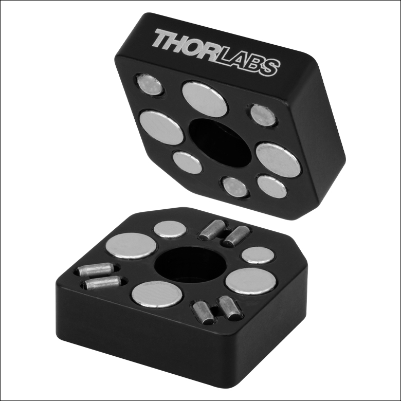
Click to Enlarge
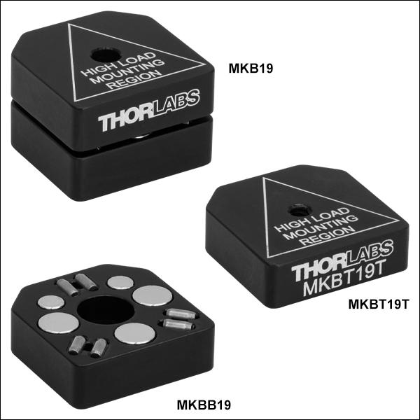
Figure G1.1 MKB19
Kinematic Base with its Five Pairs of Magnets and #4 (M3) Counterbores
- Ball and V-Groove Design Allows High-Precision Positioning
- Top Plate Included in Complete Base (Item # MKBT19) has a #4 (M3) Counterbore
- Bottom Plate Included in Complete Base (Item # MKBB19) has a #4 (M3) Counterbore
- Alternate Top Plate (MKBT19T(/M)) has a #4-40 or M3 x 0.5 Tapped Hole
Thorlabs' Mini-Series Kinematic Base is an excellent method for mounting mini-series optomechanical components that need to be inserted and removed from the optical path with a high degree of repeatability. With a ball and V-groove design, the top plate can be inserted and removed with high repeatability. The top mounting plate and bottom base plate of the MKB19 kinematic base are magnetically coupled using five pairs of high-strength magnets which provide a holding force of 1.9 lbs. Additionally, both plates have a center-located #4 (M3) counterbored hole which allows either plate to be mounted to miniseries optomechanical components like optical posts. The top plate and bottom plate are available individually (as Item #s MKBT19 and MKBB19, respectively) for applications where multiple interchangeable parts may be desired. The MKBT19 top plate is engraved to specify the high load mounting region. This illustrates the area where the center of gravity should be located for maximum stability.
Two alternate top plates (Item #s MKBT19T(/M)) are also available. These plates have a #4-40 or M3 x 0.5 tapped hole located within the high load mounting region.
Three MKB19 bases were tested for angular repeatability of position. In each case, the top plate mirror assembly was removed and replaced 50 times. During this testing, we obtained a mean angular deviation of 4.16 µrad and a maximum of 11.9 µrad (see the Repeatability tab for more information).

Click to Enlarge
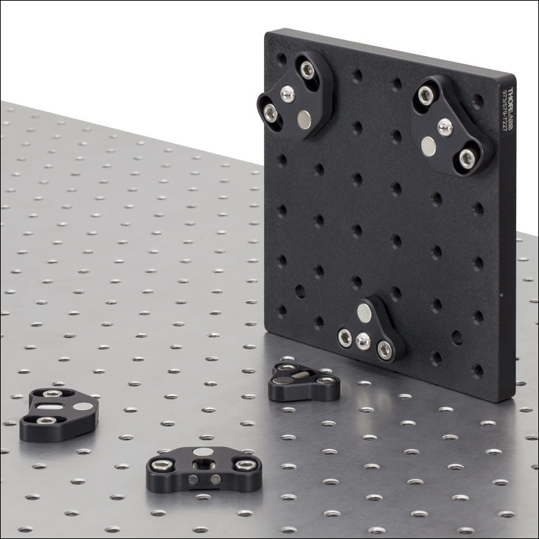
Figure G1.1 キネマティックベースセットKB1X1(KB25/M)
- ボールとV型の溝で高精度の位置決め
- セットに含まれる上部プレート(KBT25/M)はM4ザグリ穴1つ
- M4タップ穴4つ、M4ザグリ穴1つの上部プレート(KBT25T/M)もご用意
- 底部プレートにはM4ザグリ穴1つ
このキネマティックベースKB25/Mの上部取付けプレートと底部ベースプレートは、2対の強力なマグネットで磁気的に結合されています。磁力は16.0Nです。ボールとV溝により、上部プレートは高い再現性で脱着することが可能です。このベースの上部プレートは脱着しても高い再現性で元の位置に戻すことができます。上部プレートと底部プレートの中央にあるM4の貫通穴はキャップスクリュ用にザグリ穴となっており、どちらのプレートもØ12 mm~Ø12.7 mm(Ø1/2インチ)ポストへ取付けることができます。AE4M6Mのアダプタを使用すれば、このベースをM6のタップ穴付きの光学テーブルに取付けられます。また、KBT25T/Mの上部プレートには4つのM4タップ穴があります。角度再現性の試験では、平均6.36 µrad(最低0.58 µrad、最高26.72 µrad)が得られました。KB25/Mをはじめとしたキネマティックベースの再現性の試験結果については「再現性」タブをご参照ください。

 ズーム
ズーム
Click to Enlarge
Figure G2.1 キネマティックベースKB2X2(KB50/M)
- ボールとV溝により高精度の位置決めを実現
- 上部プレートには4個のM6タップ穴、4個のM4タップ穴、および1個のM6ザグリ穴
- 底部プレートにはM6ザグリ穴
- 上部プレートと底部プレートはそれぞれ単体でも、またはセットでもご提供可能
キネマティックベースKB50/Mの上部取付けプレートと底部のベースプレートのセットは、2対の強力なマグネットにより磁気的に結合されます。ボールとV溝により、上部プレートは高い再現性で脱着することが可能です。上部プレートの中央にあるM6ザグリ穴にはØ25 mmポストを取り付けられます。また上部プレートには、ザグリ穴用アダプタSD1を用いてØ12 mm~Ø12.7 mm(Ø1/2インチ)ポストのようなM4部品を取り付けることもできます。上部プレートKBT50/MにはM6タップ穴とM4タップ穴がそれぞれ4個ずつ付いているので、柔軟性の高い取付けが可能です。KB50/Mの上部プレートには三角形が刻印されており、高荷重の取付けが可能な範囲を示しています。
上部および底部プレートの側面には止まり穴があり、4 mmボール(六角)ドライバを挿入してこの2枚のプレートを取り外すことができます。また、KB50/Mに付いている3 mmの六角頭付き止めネジを用いて2枚のプレートを結合させ、使用中に上部プレートが外れないように固定できます。上部と底部が独立しているので、異なるオプトメカニクスセットアップへの交換が容易に行えます。上部プレートと底部プレートをロックするためのM4キャップスクリュは、上部および底部プレートを単体でご購入された時には付属しません。KB50/Mのマグネットの数を減らしたい(磁気的な結合を弱めたい)場合は、当社までご連絡ください。
角度再現性の試験では、平均11.87 µrad(最低3.60 µrad、最高30.96 µrad)が得られました。KB50/Mをはじめとしたキネマティックベースの再現性の試験結果については「再現性」タブをご覧ください。

 ズーム
ズーム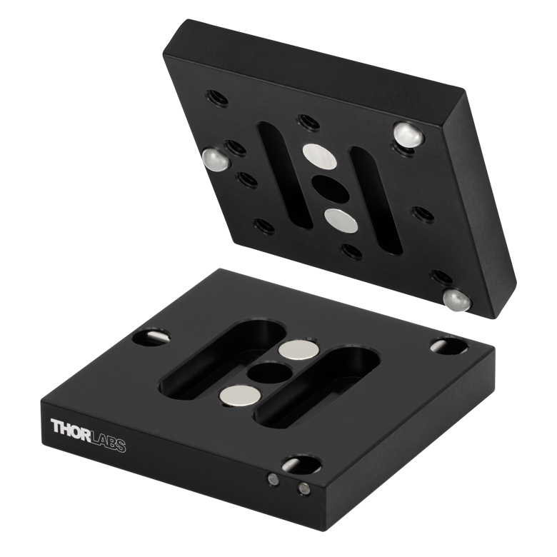
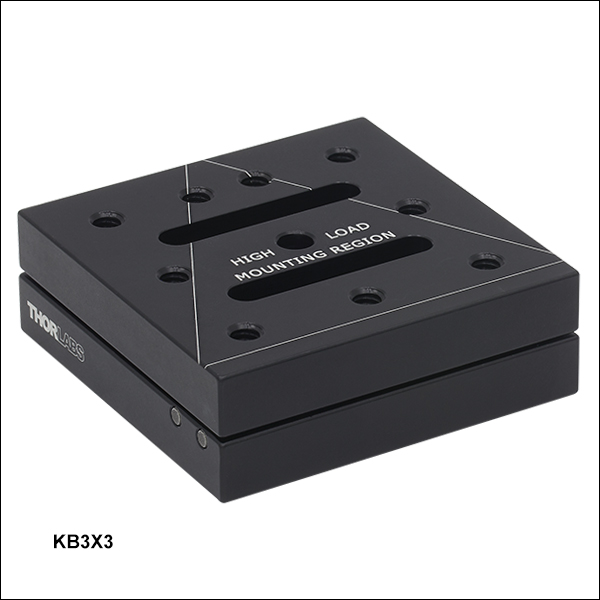
Click to Enlarge
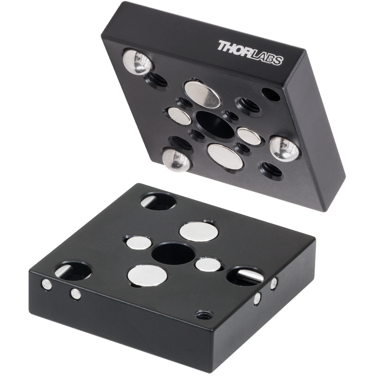
Figure G3.2 キネマティックベースセットKB3X3(KB75/M)

- ボールならびにV型溝設計が高精度の位置決めを実現
- 上部プレートには中央にM6ザグリ穴1つ、M6ザグリ穴スロット2つ、9個のM6タップ穴
- 底部プレートには中央にM6ザグリ穴1つ、M6ザグリ穴スロット2つ
- 上部プレートと底部プレートは単体、またはセットでご提供可能
キネマティックベースKB75/Mの上部取付けプレートと底部のベースプレートセットは、2対の強力なマグネットにより磁気的に結合されています。磁力は28.9Nです。ボールとV型溝設計により、上部プレートは高い再現性で脱着することが可能です。 上部プレートは、中央にあるM6の貫通穴でØ12 mm~Ø12.7 mm(Ø1/2インチ)ポストホルダに取付けることができ、かつ9個のM6ネジ穴の配列によって光学ブレッドボードと同じ取付け機能を有します。KB75/Mの上部には三角形が刻印されており、高荷重の取付けが可能な範囲を示しています。上部と底部が独立しているので、異なるオプトメカニクスセットアップへの交換が容易に行えます。
角度再現性の試験では、平均21.20 µrad(最低1.3 µrad、最高81.90 µrad)が得られました。KB75/Mをはじめとしたキネマティックベースの再現性の試験結果につきましては「再現性」タブをご覧ください。

 ズーム
ズーム
Click to Enlarge
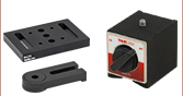
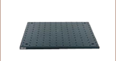
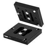
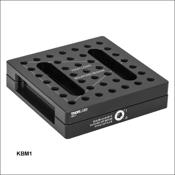
Figure G4.2 簡単脱着ブレッドボードKBM1(/M)
Click to Enlarge
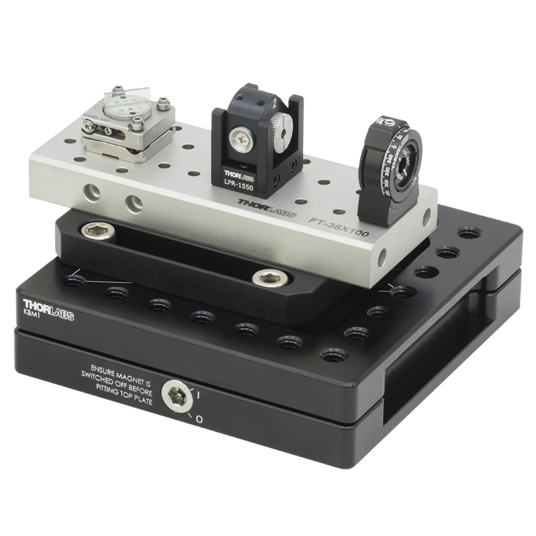
Figure G4.1 FiberBenchを取り付けたベースKBM1(/M)
- 磁力:40 N
- ボール位置決め機構ならびにV型溝設計が高精度の位置決めを実現
- 上部プレートには39個の取付け用M6タップ穴
- 上部プレートと底部プレートは単体、またはセットでご提供可能
KBM1/Mは、100.0 mm x 100.0 mm x 25.0 mmのコンパクトで高精度な薄型のロック機能付き簡単脱着マグネットブレッドボードです。 簡単脱着ブレッドボードKBM1(/M)の上部取付けプレートと底部のベースプレートセット(Figure G4.2参照)は、強力なマグネットにより磁気的に結合されています。ボール位置決め機構とV型溝設計により、上部プレートは脱着が可能です。 上部と底部が独立しているので、異なるオプトメカニクスセットアップへの交換が容易に行えます。
上部プレートには39個のM6タップ穴(深さ11.8 mm)が12.5 mm間隔で開いており、光学ブレッドボードと同様の取付機能を有しています。底部プレートには、M6キャップスクリュ用の長さ50.0 mmのザグリ穴が2つ開いているので、光学テーブルを取り付けることができます。 2つのプレート間の磁力は、5 mmの六角レンチを使って切り替え用ネジを90°回すことでオン/オフを切り替えることができます。磁力を切り替えられることにより、上部プレートは精密部品や壊れやすい機器を、損傷を与えたりミスアライメントすることを防いで取り付けることができます。
損傷を受けるのを防ぐため、上部プレートを設置する際には、底部の磁気スイッチはオフにしてください(上部プレートを設置してからスイッチを入れてください)。 プレートに取り付けたオプトメカニクスの重心を(マグネットが形成する)三角形の領域内に配置することで、上部プレートの安定性は最大になります(マグネット位置はFigure G4.1とG4.2参照)。
Figure G4.1では、KBM1/Mは当社のFiberBench FT-38X135と一緒に使用されています。 このFiberBenchシステムは、光ファイバから自由空間へのセットアップができるように設計されており、同じ光軸を保持しながら光学部品の素早い交換、挿入または取り外しが可能です。

 ズーム
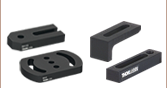
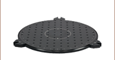
ズームClick to EnlargeFigure G5.1 キネマティックブレッドボード台座KBS98はブレッドボードをキネマティックプラットフォームに変換可能
- あらゆるブレッドボードをキネマティックプラットフォームに変換
- ボール位置決め機構ならびにV型溝設計が高精度の位置決めを実現
- ブレッドボード取付け用のM6ザグリ穴
- 上部プレートと底部プレートはセットまたは単体でご提供可能
キネマティックブレッドボード台座KBS98は、あらゆるブレッドボードを高精度で脱着できるキネマティックプラットフォームに変換することができます。KBS98は6枚のプレートで構成されています。プレートのうち3枚は底部プレートで、V溝があり、据え置き型の光学テーブルやブレッドボードに取り付けられます。他の3枚は上部プレートで、底部プレートのV溝に合う差込用ボールが付いています。台座は強力なマグネット付きです。 組み合わせて使用した場合、保持力は44.5 Nとなります。
上部プレートは、光学セットアップに脱着される光学ブレッドボードに取り付けてください。台座は光学ブレッドボードの隅/角の近くに、底部プレートにあるV溝で3角形状に配置していただくと、V溝の3軸を共通の点で位置合わせすることができます。光学ブレッドボードを最大限に安定させるためには、プレートの適切な位置決めが必要です。

 ズーム
ズーム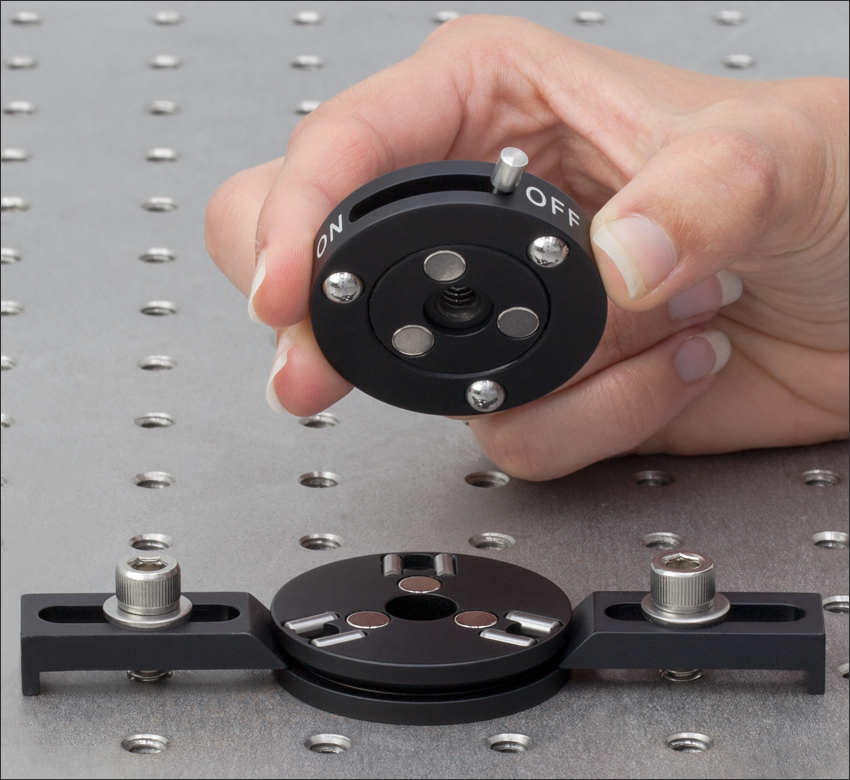
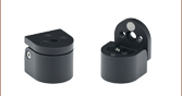
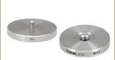
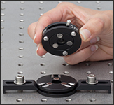
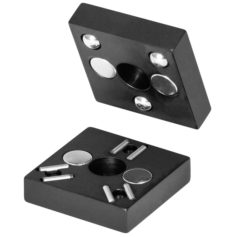
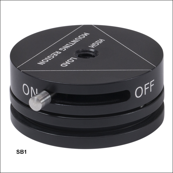
Click to EnlargeFigure G6.1 テーブルクランプCL6を用いて光学テーブルに取り付けられたキネマティックベースSB1(/M)
- プレートを結合/分離するためのOn/Offスイッチ
- SB1/MはM6タップ穴付き上部プレートとM6ザグリ穴付き底部プレートで構成
- 中央にM4タップ穴付きの上部プレートもご用意
円形キネマティックベースSB1/Mは上部プレートと底部プレートで構成されています。上部プレートと底部プレートは磁気的に結合しますが、On/Offスイッチにより容易に脱着ができます。強力な磁石により、Onにしたときの保持力は20.0 Nです。上部プレートは、ボールとV型溝により高い再現性で自動的かつ正確に元の位置に戻ります。底部プレートの中央にはM6貫通ザグリ穴があり、キャップスクリュを使ってベースを光学テーブルに取り付けることができます。またテーブルクランプCL6を底部プレートの溝に取り付け、ベース部分をFigure G6.1のように光学テーブルの任意の位置に固定することが可能です。角度再現性テストにおける平均値は11.21 µrad、最小値は0.52 µrad、最大値は159.47 µradでした。SB1/Mやその他のキネマティックベースの再現性テストの詳細については「再現性」タブをご覧ください。
円形キネマティックベースSB1/Mは、M6タップ穴付き上部プレートSB1T/Mと底部プレートSB1Bを一緒に発送いたします。なおM4タップ穴付きプレートSB1T4/Mは、SB1T/MとSB1Bのどちらにも取り付け可能ですが、別途ご購入いただく必要があります。
機構マウントベース: Ø33 mm(Ø1.3インチ)")
 ズーム
ズーム

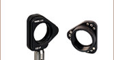
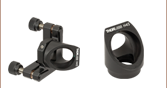
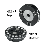
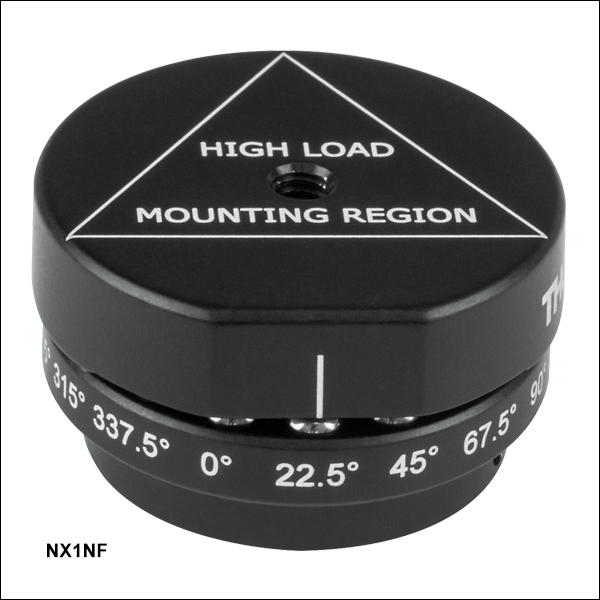
- 22.5°毎に16位置に断続回転
- 上部プレートに部品取り付け用のM4タップ穴
- 底部プレートに3つのM4取付け穴付き
- 光学部品を高い再現性で容易に交換可能
インデックス(角度割り出し)機構マウントベースNX1NF/Mは、22.5°毎に16位置に断続回転し、取り付けた部品を45°または90°に保持することも可能です。角度位置はベースプレートに刻印されているので素早いアライメントが可能です。上部プレートは高い再現性で、刻印された補助線で示されたどの位置にも戻すことができます。このマウントは、光学テーブル上の複数のターゲットにレーザの向きを変える場合や共有レーザーシステムの精密な切り替えに適しています。
最大の安定性を得るために、NX1NFT/Mの上部プレートに部品を取り付ける際は、重心が刻印されている規定の取付け範囲内(三角形の刻印部)に位置するようにしてください。
ネオジムイオン磁石が上部プレートと底部プレートを結合し、ステンレススチール製のボールベアリングとV字溝により16個所の回転位置が与えらます。底部プレートの3個のM4タップ取付け穴で、マウントベースをØ12 mm~Ø12.7 mm(Ø1/2インチ)ポストに取付けられます。ポストに取付ける際、底部プレートに刻印されている90°の位置の真下に位置する小さな貫通穴から2 mmのボール(六角)ドライバを使用すれば十分な締め付けが可能です。NX1NF/Mの磁石の磁力は上部プレートと底部プレート合わせて6.7Nです。角度再現性の試験では、平均10.6 µrad(最低0.38 µrad、最高140.50 µrad)が得られました。NX1NF(/M)をはじめとしたキネマティックベースの再現性の試験結果については「再現性」タブをご覧ください。
注: このインデックス機構マウントベースの上部プレートは、16位置のインデックス機構マウントNX1N/M(別売り)の底部プレートに取付け可能です。
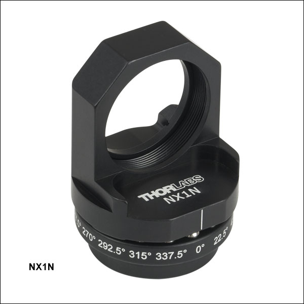
光学素子用インデックス(角度割り出し)機構マウント")
 ズーム
ズーム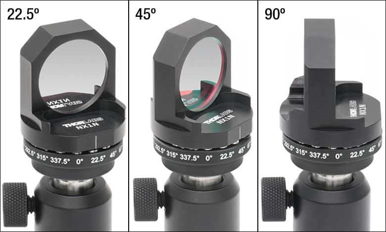
Click to Enlarge
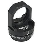
Figure 440A インデックス(角度割り出し)機構マウントNX1N(/M)が光学素子を45°ならびに90°を含む16通りの位置に保持できます。
- 22.5°毎に16位置に断続回転
- 厚さ7 mm以内のØ25 mm~Ø25.4 mm(Ø1インチ)光学素子を取付け
- 底部プレートに3つのM4取付け穴付き
- 光学部品を高い再現性で容易に交換可能
Ø25 mm~Ø25.4 mm(Ø1インチ)光学素子用インデックス(角度割り出し)機構マウントNX1N/Mには、22.5°毎に16位置に断続回転し、光学素子を45°または90°に保持することも可能です。 角度位置はベースプレートに刻印されているので素早いアライメントが可能です。 上部プレートは高い再現性で、刻印された補助線で示されたどの位置にも戻すことができます。角度再現性の試験では、平均10.6 µrad(最低0.38 µrad、最高140.50 µrad)が得られました。キネマティックベースNX1N(/M)をはじめとしたキネマティックベースの再現性の試験結果につきましては「再現性」タブをご覧ください。
付属のSM1固定リング(SM1RR)は、マウントの前側の縁に光学素子を固定します。 インデックス(角度割り出し)機構マウントは、厚さが7 mm以内の光学素子を保持します。 ネオジムと鉄を原料とした磁石が上部と底部プレートを結合し、ステンレススチール製のボールベアリングとV字溝により16個所の回転位置が与えらます。 底部プレートの3個のM4タップ穴で、マウントを12 mm~Ø12.7 mm(Ø1/2インチ)ポストに取付けられます。 マウントをポストに取付ける際、底部プレートに刻印されている90°の位置の真下に位置する小さな貫通穴から2 mmのボール(六角)ドライバを使用すれば十分な締め付けが可能です。
注:このインデックス機構マウントの上部プレートは、16ポジションのインデックス機構キネマティックベースNX1NF/M(別売り)の底部プレートに取付けることが可能です。