APTとLabVIEW
- Use APT with LabVIEW
- Download Example Virtual Instruments
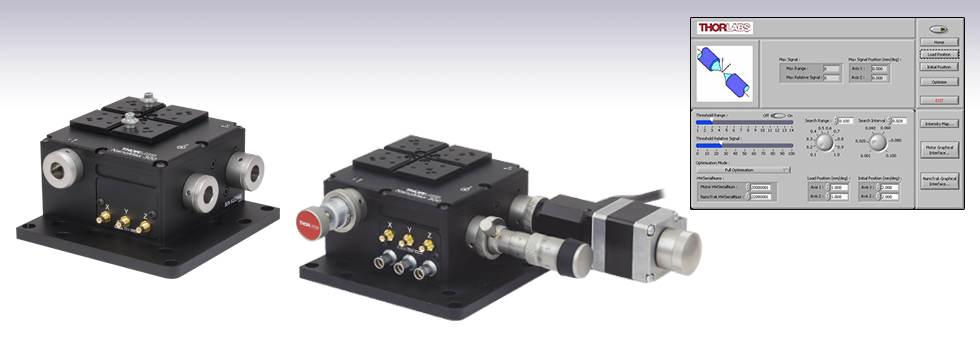
MAX302
3-Axis NanoMax Stage with 4 mm Travel and Internal Piezos
MAX301 with a Stepper Motor, Thumbscrew, and Differential Actuator Attached to the X, Y, and Z Axes, Respectively
Virtual Instrument GUI for 2-Axis Alignment Optimization

Please Wait
LabVIEWは、ActiveX技術によりあらゆるAPTベースのコントローラとの通信に使用できます。LabVIEWでは、ツールとオブジェクトでフロントパネルとして知られるユーザーインターフェイスを構築した後、グラフィカル表記の関数を使ってコードを追加し、フロントパネルのオブジェクトを制御します。LabVIEWチュートリアルでは、ActiveXを使用してAPT駆動デバイスのコントロールGUIを作成する方法がご覧いただけます。「LabVIEW」のタブではLabVIEWでAPTベースのコントローラを制御する際の基本情報が要約されています。「はじめに」のタブでは、LabVIEW GUIを用いてAPTベースのデバイスを操作する前に行うべき基本的な設定手順の解説があります。「初級VI」、「中級VI」、「上級VI」のタブには、お手持ちのコントローラのプラグラム作成に役立つ当社提供のLabVIEWの仮想計測器(VI)のサンプルをご用意しています。
LabVIEWを用いたAPT制御を行う際の包括的ガイドはこちらからダウンロードいただけます。各製品のAPTマニュアルについてはこちらをご覧ください。
Click to Enlarge
Figure 2.1 APTコントロールはLabVIEW環境に組み込むことができます。
Windows®の開発システム(LabVIEWなど)は通常、ソフトウェア開発者が使用しやすいようサードパーティのActiveXコントロールを環境に組み込めるようになっています。
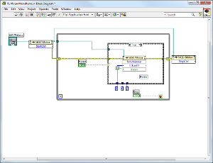
ActiveXコントロールをフロントパネルに配置後は、ほかのLabVIEWコントロールと同様の方法でご使用いただけます。なお、APTコントローラはそれぞれ下記の2つの手順で起動させる必要があります。詳細については下の青いボックス内の「LabVIEWでActiveXプロパティまたはメソッドを作成」をご覧ください。
- 「HWSerialNumber」のプロパティは、必ず(工場出荷時にプログラムされた)ハードウェアユニットのシリアルナンバに正しく設定してください。
- 「StartCtrl」のメソッドはコントロールの起動のために呼び出しが必要です。
LabVIEW環境でのAPTソフトウェアの使用ガイドはこちらからご覧ください。
注: LabVIEWのスレッド割り当ては動的です。スレッド数とスレッドの割り当て方法はアプリケーションによって異なります。アプリケーションでスレッド割り当てが重要になる場合のマルチスレッドに関する情報は下記をご覧ください。
実行可能な仮想計測器(VI)は、LabVIEW環境で一般的なプログラミングタスクを実行する初級、中級、上級サンプルと共に提供しています(「初級VI」、「中級VI」、「上級VI」のタブをご覧ください)。ソフトウェアには役立つコメントが追加され、プログラムの各ステップを詳細に説明しています。サンプルは実際のハードウェアの構成でもシミュレーションの構成でも実行可能で、当社ウェブサイトからもダウンロード可能なAPTサーバを介してハードウェアと対話します。なお、シミュレーションサーバも使用できますが、高度なアライメント操作などはシミュレーションにはない「本物」のパワーフィードバック信号が必要なため、実際のハードウェアと同様に機能しない場合があります。 サンプルには関連するハードウェアの設置や操作方法に関する情報が詳細に書かれていないため、ハンドブックも併せてご参照ください。
これらのサンプルに関する質問やご意見は当社までご連絡ください。
LabVIEWのマルチスレッド
LabVIEWではいくつか異なる種類のスレッドを割り当てます。
- ユーザーインターフェイススレッド: 画面描画、キーボード・マウス入力、プロパティノードやスレッドアンセーフのCINやDLLといった一部のVI実行に使われます。
- タイマースレッド: LabVIEWが2つのタイマースレッドを内部で使用(Windows NTがもう1つのタイマースレッドを割り当てて、内部で使用)。
- 実行スレッド: システムのCPU毎に20個の実行スレッドを使用。LabVIEWには5つの「実行システム」があり、各実行システムはスレッドを4つの異なった通常順位に割り当てます。合計すると20のスレッドで構成されていますが、これに含まれないユーザーインターフェイススレッドも実行に使用できます。実行スレッドの割り当ては、システム内のプロセッサの数に基づきます。デュアルプロセッサのPCには40の実行スレッドに加えて前述のスレッドがあります。
Windows NTでは、LabVIEWを制御するActiveXクライアントインターフェイスを使用して特定の操作向けにスレッドは動的に割り当てられています。シングルプロセッサーシステムの場合、アプリケーションの開始時には23または24のスレッドが割り当てられます。ActiveXクライアントインターフェイスをご使用の場合、仮想計測器実行中はスレッドをさらに増やすことができます。
優先順位:
サブVIは常に発呼者の実行システムを使用します。同じ実行システムを使用することが最も効率的なためです。「バックグラウンド優先順位」では通常スレッドが割り当てられていません。この優先順位で実行されているVIは他に実行できるものがなければ、次の優先順位の高いスレッドを使用します。
APTとLabVIEWのスレッドについて:
APTへはシングルスレッドのクライアントアプリケーションからのみアクセス可能です。LabVIEWはもともとマルチスレッドなので、APTソフトウェアへの1つ1つのアクセスはシングル実行スレッドに制約しなければなりません。プロパティノードは、LabVIEW環境やほかのLabVIEWベースのActiveX機能のUIスレッドへの切り替えを引き起こします。APTソフトウェアに確実にシングルスレッドでアクセスするためには、VIをユーザーインターフェイススレッドで実行する必要があります。現段階ではユーザーインターフェイススレッドでVIを実行しないとLabVIEWがAPTソフトウェアにスレッドマーシャリングできなくなり、次のLabVIEWエラーが表示されます: 「Error 3006 occurred at Automation Interface Execution System」。
LabVIEWでActiveXプロパティまたはメソッドを作成
ActiveXオブジェクトの新しい「プロパティノード」または「メソッドノード」は、関数パレットのナビゲーションなしで直接ブロックダイアグラム上に作成可能です。プロパティならびにメソッドノードは、LabVIEWのドロップダウンメニューから追加できます。
- 同じオブジェクトに対して複数のプロパティノードまたはメソッドノードを作成可能です。
- LabVIEWではメソッドノードをインボークノードと呼ぶことがあります。
ActiveXオブジェクト用にプロパティノードまたはメソッドノードを作成する方法
- ActiveXオブジェクトを右クリックし、ショートカットメニューより「作成→プロパティノード」または「作成→インボークノード」を選択する。オブジェクトはフロントパネルのActiveXコンテナ内のコントロールか、ActiveXのrefnumあるいはほかのVI、関数またはノードの端子でもよい。
- ブロックダイアグラム上で、プロパティノードまたはメソッドノードを配置したい場所をクリックする。クリックした場所にプロパティノードまたはメソッドノードが表示される。
- プロパティノードまたはメソッドノードの白い部分を右クリックし、アクセスするプロパティまたはメソッドを選択する。
LabVIEWでのメソッドの作成例はVideo 2.2~2.8でご覧いただけます。
LabVIEWでActiveXイベントを使用
ActiveXイベントは、ActiveX通信の結果として発生された特定のアクションのデータすべてが保存可能です。ActiveXイベントキューの作成、待機、破棄のVIの作成手順は下記のとおりです (注:イベントキューとはActiveXコントロールが受信するイベントの内部リストに対応するタグです)
- ブロックダイアグラム上で「Functions/Communication/ActiveX/ActiveX Events/Create ActiveX Event Queue」を選択する。
- ActiveXコンテナのrefnumまたはActiveXオートメーションのrefnumを「Create ActiveX Event Queue VI」のAutomation Refnum入力に配線する。
- 「Functions/Communication/ActiveX/ActiveX Events/Wait On ActiveX Event VI」を選択する。
- 「Create ActiveX Event Queue VI」のEvent Queue出力を「Wait On ActiveX Event VI」のEvent Queue入力に配線する。
- 「Functions/Communications/ActiveX/ActiveX Events/Destroy ActiveX Event Queue VI」を選択する。
- 「Wait On ActiveX Event VI」のEvent Queue出力を「DestroyActiveX Event Queue VI」のEvent Queue入力に配線する。
- イベントが発生するとイベントのデータがWait On ActiveX Event VIから実行可能なダイアグラム内に戻ります。
LabVIEWでのプロパティの作成例はVideo 2.2~2.8でご覧いただけます。
チュートリアルビデオ
LabVIEWによりActiveXがフルサポートされています。Video 2.2~2.8では、APTによるカスタム仕様のモーションコントロールシーケンスを作成する際の基本的な構成要素を示しています。まずソフトウェア開発中にオンラインヘルプを呼び出す方法をご紹介します。Part 2ではAPT ActiveXコントロールの作成方法をご紹介します。ActiveXコントロールではメソッド(機能)とプロパティ(数値設定)の両方を設定できます。Part 3と4では、ActiveXコントロールのメソッドとプロパティを作成してワイヤで接続する方法をご紹介します。Part 5ではまとめとして、カスタム仕様の移動シーケンスを実行するLabVIEWのプログラム例をご紹介します。
免責事項:Video 2.2~2.8は、当初はAdobe Flashによって作成されました。2020年のAdobe Flashのサポート終了後、これらのチュートリアルは再録画されています。各動画の下にはFlash Playerの操作ボタンが見えますが、機能しません。
はじめに
下記の手順はサンプル仮想計測器(VI)を使用して、APT制御デバイスに接続するためのスタートアップ手順です。このスタートアップ手順を踏んだ後、「初級VI」、「中級VI」、「上級VI」タブのVIが使用可能になります。
- ダウンロード サンプルを該当箇所(初級、中級、上級)からPCの希望の場所にダウンロードします。
- 軸の関連付け 特定のステージがシステムによって確実かつ適切に駆動されるためには、まずいくつかのパラメータを設定しなければなりません。これらのパラメータは、駆動されるステージの物理的特性に関連しています(例:最小ならびに最大位置、親ネジピッチ、ホーミング方向ほか)。パラメータの正確な設定の一助として、APT Config utilityを使用し、特定のステージタイプと軸をモーターコントローラーチャンネルに関連付けることが可能です。関連付けが終了すると、ソフトウェア起動時にAPTサーバが自動的に適切なデフォルトパラメータを適用します。ステージタイプと軸の指定方法に関する詳細についてはAPT Config Utilityのヘルプファイルをご覧ください。
- シリアルナンバの設定 ルーチンは予め設定された下記のシリアルナンバを実行するようハードコードされています。
モータ - 20000001
ピエゾ素子 - 21000001
NanoTrak® - 22000001
APTサーバでシリアルナンバは、実際のハードウェアまたはシミュレーション構成の使用に関わらず、VIダイアグラムに応じて変更する必要があります。このことについてはダイアグラムにもコメントが入っています。ハードウェアのシリアルナンバはユニットの後部に書かれています。
初級レベルの仮想計測器(VI)のサンプル
初級サンプルにはLabVIEWでAPTサーバを使い始める際に必要な情報すべてが入っていますが、カスタム仕様のベースとして使用されることを意図していません。各ActiveXコントロールがシンプルな.viファイルで関連ActiveXメソッドとプロパティの使用方法を示すことにより説明されています。また、サーバでエラーが生じた場合、そのエラーはポップアップダイアログで表示され、VIは停止します。
VIサンプルはモータ、NanoTrak、ピエゾ、歪ゲージ、そしてソレノイドの5つのコントロールに分かれて記載されています。
モータVI
モータのVIがすべて入っているZipファイルはこちらからダウンロードいただけます。
TL Motor MoveHome.vi
このVIはステージ軸をHome位置に移動させます。
関連されたステージの各軸はZero OffsetとMinimum Positionのパラメータの設定があります。Zero Offsetは負のリミットスイッチから移動終端までの距離です。Minimum Positionはステージ軸が設定可能な最小絶対位置です。通常、TL Motor MoveHome.viを実行すると、ステージ軸は負のリミットに移動して、その後設定された距離(ゼロオフセット)を前進します。その後絶対位置はゼロにリセットされ、後のすべての絶対移動の参照位置になります。ステージ軸の位置情報がなくなる場合はMove Homeのメソッドを呼び出し、ゼロ位置(Home)を再設定します。
TL Motor MoveAbsolute.vi
このVIはステージの軸を特定の絶対位置に移動させます。位置はHome位置からミリメートル単位で測定されます。
TL Motor MoveRelative.vi
このVIはステージの軸を現在の位置に対して特定の距離移動させます。
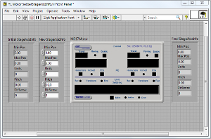
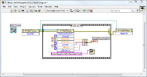
TL Motor SetGetStageAxisInfo.vi
このVIはステージのプロパティやステージの設計に特化した工場設定に関わるデータを設定または取得します。
- Unitsパラメータは、ステージの移動距離(ミリメートル)または回転角度(度)のどちらか適切な方で表記されています。
- MinPosとMaxPosパラメータはそれぞれ最小と最大移動量で、Home位置からの移動距離によって決定されます。MinPosは通常ゼロに設定されています。
- Pitchパラメータは、1回転あたりの移動距離(ミリメートル)または回転角度(度)で表記されるモータの親ネジのピッチを戻し、モータの1回転当たりの移動量の計算に使用します。
- DirSenseパラメータは今後開発用で現在使用していません。
TL Motor SetGetVelParams.vi
このVIはTL Motor MoveRelative.viまたはTL Motor MoveAbsolute.viを実行するソフトウェアにより開始される移動に適用できます。すべての移動に台形速度プロファイルのパラメータを設定可能にします。パラメータはステージタイプによりミリメートルまたは度の単位で設定されます。
TL Motor MoveComplete.vi
TL Motor MoveComplete.viを実行するにはシリアルナンバが正確に入力されなければなりません。MoveComplete.viはモータGUIパネルを表示します。ジョブボタンを押すか、位置を入力することによりモータを移動させることができます。移動完了後、MoveComplete CallBack.viが呼び出されて実行されます。2番目のVIはEventsダイアログボックスで移動完了のメッセージを表示します。
NanoTrakのVI
NanoTrakのVIがすべて入っているZipファイルはこちらからダウンロードいただけます。
TL NanoTrak LatchTrack.vi
このVIはNanoTrakのトラッキングモードを設定します。Latchedに設定された場合、走査機能が無効になり、ピエゾアクチュエータはその時点の位置で保持されます。Trackに設定されると、走査機能は有効で、NanoTrakが最大パワーの位置を追跡します。
TL NanoTrak SetGetCircDia.vi
このVIはNanoTrakの走査サークル径を設定または取得します。サークル径はNanoTrakのユニット単位で測定されます。10ユニットはスクリーンの幅と高さです。例えば、NanoTrakが20ミクロンのアクチュエータを駆動している場合、1ユニットのサークル径は実際2ミクロンとなります。走査サークル径は、0~5の範囲内の値になり、5はピエゾ移動範囲の半分に相当します。
注:注:このメソッドが呼び出されたときにNanoTrakがLatchedの状態ある場合、サークル径は変わりません。NanoTrakがTrackモードに設定されている場合、サークル径はこのメソッドにより設定された値に変更します。
TL NanoTrak SetGetCircDiaLUTVal.vi
このVIはサークル径の値(NanoTrakユニット単位)を入力範囲によって規定されているルックアップテーブル(LUT)を有効にします。システムはその段階で選択された入力範囲に対応するLUTの値を使用し、サークル径を変更します。この調整モードにより用途に応じた適切なサークル径の適用が可能となります。
TL NanoTrak SetGetCircleHomePos.vi
このVIはサークルのホーム位置を設定または取得します。現ホーム位置の水平・垂直座標は「Initial Pos」フィールドに表示されています。どちらの位置出力範囲も0.0~10.0(NanoTrakユニット単位)です。ディスプレイの原点(画面の中心)は(5.0、5.0)となります。
TL NanoTrak SetGetLoopGain.vi
このVIはフィードバックループ利得を設定または取得します。利得の設定は入力(フィードバックループ)信号のDCレベルを入力のダイナミックレンジ内に確実に収めるために使用されます。現利得は「Initial Gain」フィールドに表示されています。利得を変更したい場合には「New Gain」フィールドに値(100~10,000まで)を入力してください。
TL NanoTrak SetGetPhaseComp.vi
このVIは走査サークル経路の水平ならびに垂直成分の位相補償を設定または取得します。
典型的なNanoTrakの使用用途においてフィードバックループは、様々な電子部品や電気機械部品(パワーメータやピエゾアクチュエータなど)の動作と関わりがあり、これらの部品がループに位相シフトをもたらすことによりフィードバックの効率性や安定性に影響を与える場合があります。このような位相シフトは「Phase Compensation」係数を設定することにより補償できます。このVIは走査サークル経路の水平ならびに垂直成分の位相補償を設定または取得します。
現在の値は「Initial Phase Comp」フィールドに表示されています。変更したい場合には「New Phase Comp」フィールドに異なる値を入力してください。値は度で表記されており、範囲は-180.0~180.0度となります。通常どちらの位相オフセットも同じ値に設定しますが、電気機械システムによっては移動の異なる成分に異なる位相遅れが発生し、値が異なる場合があります。
TL NanoTrak SetGetRangingMode.vi
このVIはレンジングモードを設定または取得します。現在選択されているレンジングモードは「Initial Ranging Mode」フィールドの1番目のボックスに表示されています。1~4の番号を入力することにより設定が可能です。
- 現在選択されているレンジでレンジングモードをAutoに変更
- 現在選択されているレンジでレンジングモードをManualに変更
- SetRangeメソッド(または「Settings」パネル)で設定されたレンジでレンジングモードをManualに変更。Autoレンジングモードが選択されている場合、相対入力パワー信号が現在設定されているレンジの上限または下限に達するとレンジが変更します。
- SetRangeメソッド(または「Settings」パネル)で設定されたレンジでレンジングモードをAutoに変更。Autoレンジングモードが選択されている場合、相対入力パワー信号が現在設定されているレンジの上限または下限に達するとレンジが変更します。
「Initial Ranging Mode」フィールドの2番目のボックスにはシステムのレンジ変更実施方法が指定されます。
- ユニットは2つの入力信号レベルの間のレンジすべてにアクセスする
- ユニットは2つの入力信号レベルの間の奇数番号のレンジのみアクセスする
- 2つの入力信号レベルの間の偶数番号のレンジのみアクセスする。後者の2つのモードは入力信号の変動が大きく速いと予測されるときに便利です。アクセスするレンジ数が半分なので、応答が速くなるからです。
レンジングモードを変更したい場合には「New Ranging Mode」フィールドに異なる値を入力してください。
ピエゾ素子のVI
ピエゾ素子のVIがすべて入っているZipファイルはこちらからダウンロードいただけます。
TL Piezo GetMaxTravel.vi
位置センサが内蔵されているアクチュエータの場合、ピエゾコントロールユニットはアクチュエータの移動範囲を検知することができます。情報がアクチュエータ内の電子回路にプログラムされているからです。このVIは、lChanIDパラメータで指定されているチャンネルに関連するピエゾアクチュエータの最大移動量を取得し、plMaxTravelパラメータに値(ミクロン単位)を戻します。
TL Piezo SetGetControlMode.vi
閉ループモードの場合、位置はピエゾアクチュエータからのフィードバック信号によって保持されています。これは位置センサ付きのアクチュエータを使用しているときのみ可能です。このVIは制御ループステータスを設定します。詳細についてはAPTサーバーヘルプファイル(APTインストール後は「スタート/すべてのプログラム/Thorlabs/APT/Help」で)をご覧ください。
TL Piezo SetGetPosOutput.vi
このVIはピエゾアクチュエータの位置を設定または取得します。
アクチュエータの現在の位置は「Initial Position」フィールドで表示されています。アクチュエータの位置はZeroPositionメソッドで設定したゼロ位置との相対位置です。設定後、コントロールモジュールに接続されているアクチュエータの変位量がミクロン単位で読み込まれます。注: SetPosOutput VIは位置センサ内蔵のアクチュエータが閉ループモードで動作している場合のみに適用されます。フィードバック回路が付いているアクチュエータは、ピエゾモジュールによりミクロン単位の最大移動量を取得することが可能です(GetMaxTravel.vi参照)。
アクチュエータの位置は「New Position」フィールドに異なる値を入力することにより変更できます。
TL Piezo SetOutputLUTValue.vi
コントローラは任意波形発生モード(WGM)で使用可能です。ユニットによる調整可能で静的な電圧または位置出力ではなく、WGMはサンプリング間隔が選択可能となるユーザ定義の電圧または位置シーケンスを周期的または決められた回数で出力します。この波形発生機能は、特定のエリアを走査したり、あらかじめ定義した移動シーケンスが必要なアプリケーションに特に役立ちます。
波形は電圧または位置を表す値として配列に保存されており、チャンネル毎の最大サンプル数が8000です。チャンネルが開ループ動作の場合、配列の値は電圧です。閉ループ動作の場合、配列の値は位置です。出力波形のサンプル数が8000以下の場合、任意のサンプル数を指定できます。
歪ゲージのVI
歪ゲージVIがすべて入っているZipファイルはこちらからダウンロードいただけます。
TL Strain Guage Reader GetReading.vi
このVIは歪ゲージの現在の値を戻します。
単位はその時点での動作モードによります。ユニットがPositionモードで動作している場合、VIはミクロン単位の位置値を戻します。ユニットがVoltageモードで動作している場合、VIはボルト単位の電圧値を戻します。コントローラが「Force Sensing Mode」で動作している場合、ニュートン単位の発生力値が戻されます。戻り値は500 Hzでサンプリングされています。これは力の測定値を素早くポーリングすることが重要なタッチプローブやフォースセンシングアプリケーションに特に便利です。
すべての値はZeroPositionメソッドで設定した値との相対値です。
SolenoidのVI
SolenoidVIがすべて入っているZipファイルはこちらからダウンロードいただけます。
TL SetOperatingMode.vi
このVIはソレノイドコントローラーユニットの動作モードを設定します。 詳細についてはAPTサーバーヘルプファイル(APTインストール後は「スタート/すべてのプログラム/Thorlabs/APT/Help」で)をご覧ください。
中級レベルの仮想計測器(VI)のサンプル
中級レベルのサンプルにはAPTサーバを用いて書いたルーチンを5つご用意しています。これらのVIはカスタムプログラムを書く際の例として使用することを意図しています。すべてのパラメータはハードコーディングされています。サンプルをカスタムプログラム開発のベースとして使用する前にパラメータの変更が必要な場合もあります。例えば、走査ルーチンでは異なる開始点と間隔値が必要かもしれません。サーチ中、位置決め用パワーレンジの閾値も異なる場合があります。また、サーバでエラーが生じた場合、そのエラーはポップアップダイアログで表示され、VIは停止します。
各VIの機能は下記で簡単に説明しています。ファイルはこちらからダウンロードいただけます。
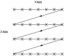
Figure 5.1 2次元ラスタ走査パターン
Motor2DScan.vi
このVIは、モーターコントロールを使用した最も基本的な2次元ラスタ走査を示します。座標はY軸に沿ってサーチ下限値と上限値の間で生成されます。上限値に達すると、サーチはZ軸の次のステップに進み、同様の手順が始まります。座標の数はサーチエリアとステップサイズによって異なります。
MotorScan2DFindRange.vi
このVIはMotor 2D Scanの拡張です。NanoTrakコントロールが含まれ、サーチしている信号が予め定義した閾値を超えると走査が終了します。
Piezo2DScan.vi
このVIはピエゾコントロールを使用した基本的な2次元ラスタ走査を示します。
これは最も基本的な走査パターンです。座標はY軸に沿ってサーチ下限値と上限値の間で生成されます。上限値に達すると、サーチはZ軸の次のステップに進み、同様の手順が始まります。座標の数はサーチエリアとステップサイズによって異なります。
PiezoNanoTrak2DScanFindRange.vi
このVIはPiezo 2D Scanの拡張です。NanoTrakコントロールが含まれ、サーチしている信号が予め定義した閾値を超えると走査が終了します。
MotorNanoTrak2DRevector.vi
すべてのアプリケーションにおいてNanoTrakがトラッキングモードに設定されているとき、信号のトラッキングはピエゾの移動量に限られています。熱ドリフトほか外部の影響によりNanoTrakが画面の端に達した場合、ピエゾの移動範囲を超えるため信号が失われます。リベクトルルーチンがサークルの位置を確認します。サークルの位置がNanoTrakの画面中心付近からずれた場合、モータを使用し、NanoTrakが信号をトラッキングすることができるように十分なサーチ範囲を確保します。
上級レベルの仮想計測器(VI)のサンプル
ここではステッピングモータ(NanoSteps)とピエゾポジショナを組み合わせてアライメント調整を行う方法をご紹介します。ステッピングモータで広い範囲を移動して粗調整を行い、もう一方のピエゾ素子で狭い範囲内での微調整を行います。ピエゾ素子はNanoTrak®で駆動しますが、このアナログ回路の装置は、検出される光パワーが最大となるようにピエゾ素子の長さを最適調整することができます。
上級レベルのサンプルにはAPTサーバを用いて書いたルーチンを5つご用意しています。これらのVIはカスタムプログラムを書く際の例として使用することを意図しています。サンプルをカスタムプログラム開発のベースとして使用する前に、コードの一部変更が必要な場合もあります。例えば最適化の順番やプロセスに変更が必要かもしれません。また、サーバでエラーが生じた場合、そのエラーはポップアップダイアログで表示され、VIは停止します。エンドアプリケーションではより複雑なエラー処理が必要となる場合があります。各VIの機能は下記で説明しています。上級VIサンプルがすべて入っているZipファイルはこちらからダウンロードいただけます。
注: これらのVIには、数セットの軸に沿ったアライメントの最適化を説明するためのサンプルコードが含まれています。コードはほかのプログラムで使用可能ですが、エンドアプリケーションの一部として実行するためにはさらに高度なエラー処理を追加する必要があります。
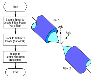
Figure 6.1 2軸最適化のフローチャート
2軸最適化
このVIは2軸に沿って2つのパーツのアライメントを最適化します(例えば2本のファイバをアライメントし、1本からの出射光をもう1本に最大限に結合させるなど)。NanoStepモータによって2次元のスパイラルサーチが行われ、初期(閾値)パワーを見つけ出します。その後、ピエゾ素子を用いて適切なパワーを見つけ出します。必要に応じてリベクトルが行われます。手順はFigure 6.1にまとめています。
上級VIサンプルがすべて入っているZipファイルはこちらからダウンロードいただけます。
NanoMaxステージのセットアップ
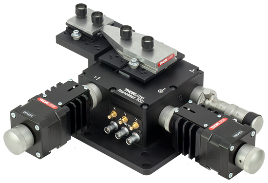
この例では、Figure 6.2のようにNanoMaxステージに2つのV溝ファイバーホルダを取り付けます。使用されているメカニクス部品はTable 6.3に載っています。アライメントが必要な部品はユーザによって異なるのでセットアップ内には含まれていません。デバイスのマニュアルに記載されているようにNanoMaxステージをPCに接続してください。
Click to Enlarge
Figure 6.2 2軸最適化VIにおけるNanoMaxステージのセットアップ。使用されている部品の型番はTable 6.3に記載されています。
| Table 6.3 2-Axis Configuration Components | ||
|---|---|---|
| Item # | Description | Quantity |
| MAX301 or MAX302 | NanoMax-HS 3-Axis Stage | 1 |
| DRV001 | NanoStep Actuator | 2 |
| DRV3 | Differential Micrometer | 1 |
| AMA007 or AMA009 | Fixed World Bracket | 1 |
| HFV001 | Standard V-Groove Fiber Holdera | 1 |
| HFV002 | Tapered V-Groove Fiber Holdera | 1 |
| HFC005 | Standard Fiber Chuck | 1 |
| BNT001/IR | APT NanoTrak® Controller | 1 |
| BSC202 | APT Stepper Motor Controller | 1 |
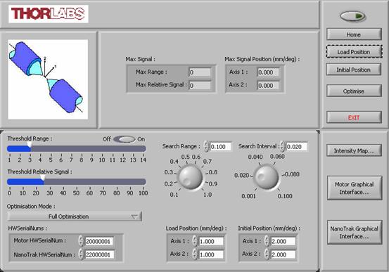
Figure 6.4 2軸最適化VIのGUI
2軸最適化GUI
2軸最適化VIのGUIがFigure 6.4でご覧いただけます。各項目の説明がTable 6.5に記載されています。GUIの実行方法は以下の通りです。
- システムが「はじめに」のタブに記載されている通りセットアップされているかどうか確認する。
- 電源を入れる。
- LabVIEWを開き、2AxisOptimization.viファイルを実行する。
- ステッピングモータとNanoTrakユニットのシリアルナンバを入力する。
- Threshold RangeとThreshold Relative Signalに用途に応じて適切な値を設定し、ThresholdのスライドスイッチをOnに設定する。
- Search RangeとSearch Intervalに用途に応じて適切な値を入力する。
- Load PositionとInitial Positionに値を入力する(デフォルトの値はほとんどの用途を満たす値となっています)。
-
 ボタンをクリックしてソフトウェアとハードウェア間の通信を開始する。
 - HomeボタンをクリックしてモータがHome位置に移動するまで待つ。
- Load Positionボタンをクリックしてモータがアライメント部品の着脱位置に移動するまで待つ。
- アライメントするデバイスを取り付ける。
- Initial Positionボタンをクリックしてモータが初期位置に移動するまで待つ。
- ご希望のOptimization Modeを選択して、Optimizeボタンを押すと最適化のシーケンスが開始されます。
- パワー閾値が見つからない場合、Threshold RangeとThreshold Relative Signalを低い値に設定してみてください。
注意事項:
- アライメント中、最大信号レベルとその位置はMax SignalとMax Signal Positionに表示されます。
- アライメントシーケンスが終了するとNanoTrakは「Latch」モードに設定されます。
- Search Rangeには大きな値、かつ・またはSearch Intervalに小さな値が設定されている場合、走査座標を生成するのに時間を要する場合があります。座標を生成するのにかかる実際の所要時間はPCの性能によって異なります。
| Table 6.5 2-Axis VI GUI Field Descriptions | ||
|---|---|---|
| Field Name | Description | |
| Max Signal | Displays the maximum power located during the search. The power is displayed as a relative signal and a range value. | |
| Max Signal Position | Displays the position at which the maximum power was located. | |
| Threshold Range and Relative Signal | The combination of these two settings determines the power level to be located by the spiral search. The search is terminated when the threshold level is exceeded. The level set should be higher than the noise floor to ensure the NanoTrak® does not track to a false power peak. | |
| Search Range and Interval | The range and interval (step size) of the search pattern (in mm). | |
| Optimization Mode | The type of optimization to perform. Select from: | Full Optimization: A complete optimization including NanoTrak scan for max power. |
| Stop Optimization Upon Threshold Signal: The optimization is stopped once the level of power found exceeds the threshold level set for the 2D scan. If no threshold level is set, a full 2D scan is performed. The system then moves to the position where max power was located. | ||
| HWSerialNums | Enter the serial numbers of each APT unit in the system. | |
| Load Position | Moves all the motors to the initial position. These are the safe positions where load or unload operations can be performed. The positions are measured in mm (or degrees) from the Home position. | |
| Initial Position | The position of the motors immediately prior to the commencement of an optimization. The position is measured in mm (or degrees) from the Home position. | |
| Home | Moves all motors to the Home position. | |
| Load Position | Moves all motors to the initial position. | |
| Optimize | Start button for the optimization. | |
| Exit | Stops the current LabVIEW VI. To restart a VI, select 'Run' from the LabVIEW environment. | |
| Intensity Map | Displays a graphical representation of the search results. | |
| Motor Graphical Interface | Displays the GUI panel for the stepper motor controller unit whose serial number is selected in the HWSerialNums field. | |
| NanoTrak® Graphical Interface | Displays the GUI panel for the NanoTrak unit whose serial number is selected in the HWSerialNums field. | |
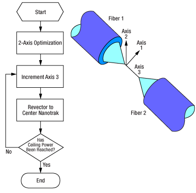
Figure 6.6 3軸最適化のフローチャート
3軸最適化
このVIは3軸アライメントの最適化に使用されます。まず2次元のスパイラルサーチがNanoStepモータによって実行され、初期(閾値)パワーを見つけ出します。ピエゾ素子を用いて適切なパワーを見つけ出します。必要に応じてリベクトルが行われます。軸1と2の最大パワーが見つかると、軸3の位置を調整することによりパワーがさらに最適化されます。一方で軸1と2の位置はNanoTrakを「そっと動かす」ことにより維持されます。最大パワーが得られるとアライメントは終了します。
上級VIサンプルがすべて入っているZipファイルはこちらからダウンロードいただけます。
NanoMaxステージのセットアップ
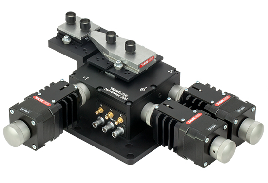
この例では、Figure 6.7のようにNanoMaxステージに2つのV溝ファイバーホルダを取り付けます。使用されているメカニクス部品はTable 6.8に載っています。アライメントが必要な部品はユーザによって異なるのでセットアップ内には含まれていません。デバイスのマニュアルに記載されているようにNanoMaxステージをPCに接続してください。
Click to Enlarge
Figure 6.7 3軸最適化VIにおけるNanoMaxステージのセットアップ。使用されている部品の型番はTable 6.8に記載されています。
| Table 6.8 3-Axis Configuration Components | ||
|---|---|---|
| Item # | Description | Quantity |
| MAX301 or MAX302 | NanoMax-HS 3-Axis Stage | 1 |
| DRV001 | NanoStep Actuator | 3 |
| AMA007 or AMA009 | Fixed World Bracket | 1 |
| HFV001 | Standard V-Groove Fiber Holdera | 1 |
| HFV002 | Tapered V-Groove Fiber Holdera | 1 |
| HFC005 | Standard Fiber Chuck | 1 |
| BNT001/IR | APT NanoTrak® Controller | 1 |
| BSC202 | APT Stepper Motor Controller | 1 |
3軸最適化GUI
3軸最適化VIのGUIがFigure 6.9でご覧いただけます。各項目の説明がTable 6.10に記載されています。GUIの実行方法は以下の通りです。
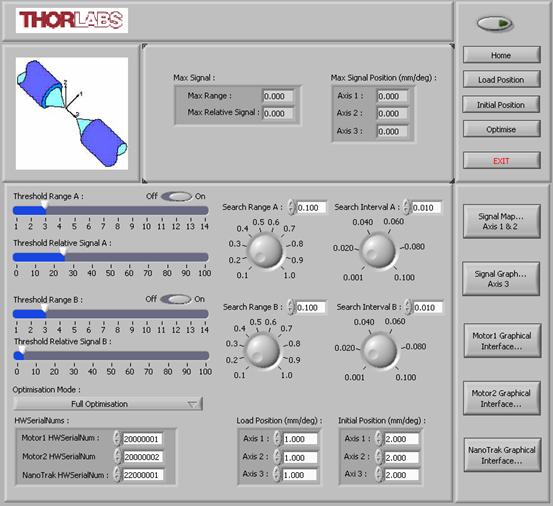
Figure 6.9 3軸最適化VIのGUI
- システムが「はじめに」のタブに記載されている通りセットアップされているかどうか確認する。
- 電源を入れる。
- LabVIEWを開き、3AxisOptimization.viファイルを実行する。
- ステッピングモータとNanoTrakユニットのシリアルナンバを入力する。
- Threshold Range AとThreshold Relative Signal Aに用途に応じて適切な値を設定し、ThresholdのスライドスイッチをOnに設定する。
- Search Range AとSearch Interval Aに用途に応じて適切な値を入力する。
- Threshold Range BとThreshold Relative Signal Bに用途に応じて適切な値を設定し、ThresholdのスライドスイッチをOnに設定する。
- Search Range BとSearch Interval Bに用途に応じて適切な値を入力する。
- Load PositionとInitial Positionに値を入力する(デフォルトの値はほとんどの用途を満たす値となっています)。
-
 ボタンをクリックしてソフトウェアとハードウェア間の通信を開始する。
 - HomeボタンをクリックしてモータがHome位置に移動するまで待つ。
- Load Positionボタンをクリックしてモータがアライメント部品の着脱位置に移動するまで待つ。
- アライメントするデバイスを取り付ける。
- Initial Positionボタンをクリックしてモータが初期位置に移動するまで待つ。
- ご希望のOptimization Modeを選択して、Optimizeボタンを押すと最適化のシーケンスが開始されます。
- パワー閾値が見つからない場合、Threshold Range AとThreshold Relative Signal Aを低い値に設定してみてください。
注意事項:
- アライメント中、最大信号レベルとその位置はMax SignalとMax Signal Positionに表示されます。
- アライメントシーケンスが終了するとNanoTrakは「Latch」モードに設定されます。
- Search Rangeには大きな値、かつ・またはSearch Intervalに小さな値が設定されている場合、走査座標を生成するのに時間を要する場合があります。座標を生成するのにかかる実際の所要時間はPCの性能によって異なります。
| Table 6.10 3-Axis VI GUI Field Descriptions | ||
|---|---|---|
| Field Name | Description | |
| Max Signal | Displays the maximum power located during the search. The power is displayed as a relative signal and a range value. | |
| Max Signal Position | Displays the position at which the maximum power was located. | |
| Threshold Range A and Relative Signal A | The combination of these two settings determines the signal level to be located by the spiral search on axes 1 and 2. The search is terminated when the threshold level is exceeded. The signal level set should be higher than the noise floor to ensure the NanoTrak® does not track to a false power peak. | |
| Search Range A and Interval A | The range and interval (step size) of the search pattern (in mm). | |
| Threshold Range B and Relative Signal B | The combination of these two settings determines the signal level to be located by the step search on axis 3. The search is terminated when the threshold level is exceeded. The signal level set should be higher than that set for search A and less than or equal to the maximum signal level expected for the application. | |
| Search Range B and Interval B | The range and interval (step size) of the step search (in mm). | |
| Optimization Mode | The type of optimization to perform. Select from: | Full Optimization: A complete optimization including NanoTrak scan for max power. |
| Stop Optimization Upon Threshold Signal: The optimization is stopped once the level of power found exceeds the threshold level set for the 2D scan. If no threshold level is set, a full 2D scan is performed. The system then moves to the position where max power was located. | ||
| HWSerialNums | Enter the serial numbers of each APT unit in the system. | |
| Load Position | Moves all the motors to the initial position. These are the safe positions where load or unload operations can be performed. The positions are measured in mm (or degrees) from the Home position. | |
| Initial Position | The position of the motors immediately prior to the commencement of an optimization. The position is measured in mm (or degrees) from the Home position. | |
| Home | Moves all motors to the Home position. | |
| Load Position | Moves all motors to the initial position. | |
| Optimize | Start button for the optimization. | |
| Exit | Stops the current LabVIEW VI. To restart a VI, select 'Run' from the LabVIEW environment. | |
| Intensity Map | Displays a graphical representation of the search results. | |
| Motor Graphical Interface | Displays the GUI panel for the stepper motor controller unit whose serial number is selected in the HWSerialNums field. | |
| NanoTrak® Graphical Interface | Displays the GUI panel for the NanoTrak unit whose serial number is selected in the HWSerialNums field. | |
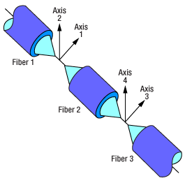
Figure 6.11 4軸最適化のフローチャート
4軸最適化
このVIは2台のNanoMaxステージを2軸ずつに沿ってアライメントする際に便利です。Figure 6.11では各軸の定義を示しています。2次元スパイラルサーチがNanoStepモータにより軸1と2、そして軸3と4に実行されます。初期(閾値)パワーが見つかると、ピエゾ素子を用いて最適化します。必要に応じてリベクトルが行われます。トラッキングはアライメントされているデバイスのそれぞれの端で2台のNanoTrak(異なる周波数に設定)で同時に行われます。
上級VIサンプルがすべて入っているZipファイルはこちらからダウンロードいただけます。
NanoMaxステージのセットアップ
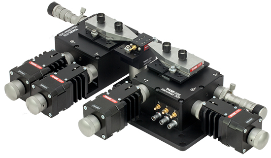
この例では、Figure 6.12のようにNanoMaxステージに2つのV溝ファイバーホルダを取り付けます。使用されているメカニクス部品はTable 6.13に載っています。アライメントが必要な部品はユーザによって異なるのでセットアップ内には含まれていません。デバイスのマニュアルに記載されているようにNanoMaxステージをPCに接続してください。
Click to Enlarge
Figure 6.12 4軸最適化VIにおけるNanoMaxステージのセットアップ。使用されている部品の型番はTable 6.13に記載されています。
| Table 6.13 4-Axis Configuration Components | ||
|---|---|---|
| Item # | Description | Quantity |
| MAX301 or MAX302 | NanoMax-HS 3-Axis Stage | 2 |
| DRV001 | NanoStep Actuator | 4 |
| DRV3 | Differential Micrometer | 2 |
| AMA029C | Fixed Platform | 1 |
| HWV001 | Waveguide Mount with Vacuum Holddowna | 1 |
| HFV002 | Tapered V-Groove Fiber Holdera | 1 |
| BNT001/IR | APT NanoTrak® Controller | 2 |
| BSC202 | APT Stepper Motor Controller | 2 |
4軸最適化GUI
4軸最適化VIのGUIがFigure 6.14でご覧いただけます。各項目の説明がそのTable 6.15に記載されています。GUIの実行方法は以下の通りです。
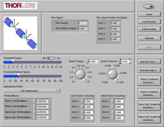
Figure 6.14 4軸最適化VIのGUI
- システムが「はじめに」のタブに記載されている通りセットアップされているかどうか確認する。
- 電源を入れる。
- LabVIEWを開き、4AxisOptimization.viファイルを実行する。
- ステッピングモータとNanoTrakユニットのシリアルナンバを入力する。
- Threshold RangeとThreshold Relative Signalに用途に応じて適切な値を設定し、ThresholdのスライドスイッチをOnに設定する。
- Search RangeとSearch Intervalに用途に応じて適切な値を入力する。
- Load PositionとInitial Positionに値を入力する(デフォルトの値はほとんどの用途を満たす値となっています)。
-
 ボタンをクリックしてソフトウェアとハードウェア間の通信を開始する。
 - HomeボタンをクリックしてモータがHome位置に移動するまで待つ。
- Load Positionボタンをクリックしてモータがアライメント部品の着脱位置に移動するまで待つ。
- アライメントするデバイスを取り付ける。
- Initial Positionボタンをクリックしてモータが初期位置に移動するまで待つ。
- ご希望のOptimization Modeを選択して、Optimizeボタンを押すと最適化のシーケンスが開始されます。
- パワー閾値が見つからない場合、Threshold RangeとThreshold Relative Signalを低い値に設定してみてください。
注意事項:
- アライメント中、最大信号レベルとその位置はMax SignalとMax Signal Positionに表示されます。
- アライメントシーケンスが終了するとNanoTrakは「Latch」モードに設定されます。
- Search Rangeには大きな値、かつ・またはSearch Intervalに小さな値が設定されている場合、走査座標を生成するのに時間を要する場合があります。座標を生成するのにかかる実際の所要時間はPCの性能によって異なります。
| Table 6.15 4-Axis VI GUI Field Descriptions | ||
|---|---|---|
| Field Name | Description | |
| Max Signal | Displays the maximum power located during the search. The power is displayed as a relative signal and a range value. | |
| Max Signal Position | Displays the position at which the maximum power was located along each axis. | |
| Threshold Range and Relative Signal | The combination of these two settings determines the signal level to be located by the spiral search on axes 1 and 2. The search is terminated when the threshold level is exceeded. The signal level set should be higher than the noise floor to ensure the NanoTrak® does not track to a false power peak. | |
| Search Range and Interval | The range and interval (step size) of the search pattern (in mm). | |
| Optimization Mode | The type of optimization to perform. Select from: | Full Optimization: A complete optimization including NanoTrak scan for max power. |
| Stop Optimization Upon Threshold Signal: The optimization is stopped once the level of power found exceeds the threshold level set for the 2D scan. If no threshold level is set, a full 2D scan is performed. The system then moves to the position where max power was located. | ||
| HWSerialNums | Enter the serial numbers of each APT unit in the system. | |
| Load Position | Moves all the motors to the initial position. These are the safe positions where load or unload operations can be performed. The positions are measured in mm (or degrees) from the Home position. | |
| Initial Position | The position of the motors immediately prior to the commencement of an optimization. The position is measured in mm (or degrees) from the Home position. | |
| Home | Moves all motors to the Home position. | |
| Load Position | Moves all motors to the initial position. | |
| Optimize | Start button for the optimization. | |
| Exit | Stops the current LabVIEW VI. To restart a VI, select 'Run' from the LabVIEW environment. | |
| Intensity Map | Displays a graphical representation of the search results. | |
| Motor Graphical Interface | Displays the GUI panel for the stepper motor controller unit whose serial number is selected in the HWSerialNums field. | |
| NanoTrak® Graphical Interface | Displays the GUI panel for the NanoTrak unit whose serial number is selected in the HWSerialNums field. | |
6軸最適化
このVIは2台のNanoMaxステージを3軸ずつに沿って、真ん中の部品にアライメントする際に便利です。2次元のスパイラルサーチが軸1と2、そして軸3と4同時に実行されます。NanoStepモータによって初期(閾値)のパワーが見つかります。その後、ピエゾ素子を用いて最適化します。必要に応じてリベクトルが行われます。軸1、2、3と4の最大パワーが見つかると、軸5と6の位置を調整することによりパワーがさらに最適化されます。一方で軸1、2、3と4の位置はNanoTrakを「そっと動かす」ことにより維持されます。
トラッキングはアライメントされているデバイスのそれぞれの端で2台のNanoTrak(異なる周波数に設定)で同時に行われます。同様に走査サークルがNanoTrakの中心にくるように軸1、2、3と4が調整されます。最大パワーが得られるとアライメントは終了します。
上級VIサンプルがすべて入っているZipファイルはこちらからダウンロードいただけます。
NanoMaxステージのセットアップ
この例では、Figure 6.16のようにNanoMaxステージに2つのV溝ファイバーホルダを取り付けます。使用されているメカニクス部品はTable 6.17に載っています。アライメントが必要な部品はユーザによって異なるのでセットアップ内には含まれていません。デバイスのマニュアルに記載されているようにNanoMaxステージをPCに接続してください。
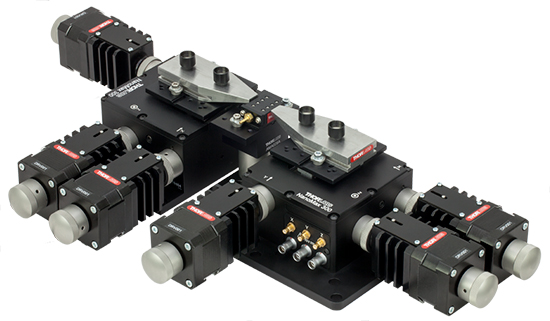
Click to Enlarge
Figure 6.16 6軸最適化VIにおけるNanoMaxステージのセットアップ。使用されている部品の型番はTable 6.17に記載されています。
| Table 6.17 6-Axis Configuration Components | ||
|---|---|---|
| Item # | Description | Quantity |
| MAX301 or MAX302 | NanoMax-HS 3-Axis Stage | 2 |
| DRV001 | NanoStep Actuator | 6 |
| AMA029C | Fixed Platform | 1 |
| HWV001 | Waveguide with Vacuum Holddowna | 1 |
| HFV002 | Tapered V-Groove Fiber Holdera | 2 |
| HFC005 | Standard Fiber Chuck | 1 |
| BNT001/IR | APT NanoTrak® Controller | 2 |
| BSC202 | APT Stepper Motor Controller | 2 |
6軸最適化GUI
6軸最適化VIのGUIがFigure 6.18でご覧いただけます。各項目の説明がそのTable 6.19に記載されています。GUIの実行方法は以下の通りです。
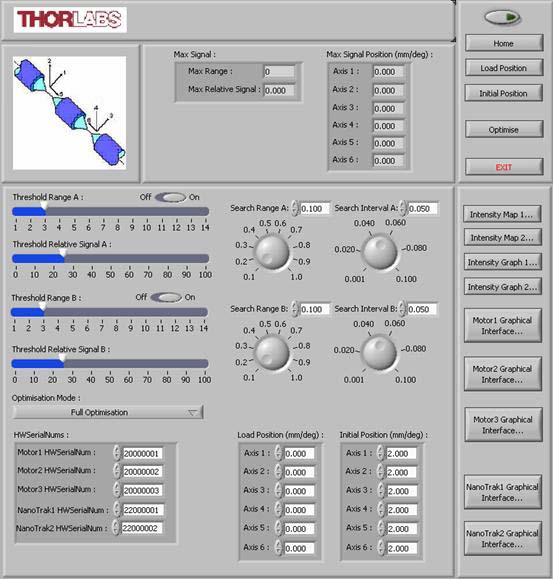
Figure 6.18 6軸最適化VIのGU
- システムが「はじめに」のタブに記載されている通りセットアップされているかどうか確認する。
- 電源を入れる。
- LabVIEWを開き、6AxisOptimization.viファイルを実行する。
- ステッピングモータとNanoTrakユニットのシリアルナンバを入力する。
- Threshold Range AとThreshold Relative Signal Aに用途に応じて適切な値を設定し、ThresholdのスライドスイッチをOnに設定する。
- Search Range AとSearch Interval Aに用途に応じて適切な値を入力する。
- Threshold Range BとThreshold Relative Signal Bに用途に応じて適切な値を設定し、ThresholdのスライドスイッチをOnに設定する。
- Search Range BとSearch Interval Bに用途に応じて適切な値を入力する。
- Load PositionとInitial Positionに値を入力する(デフォルトの値はほとんどの用途を満たす値となっています)。
-
 ボタンをクリックしてソフトウェアとハードウェア間の通信を開始する。
 - HomeボタンをクリックしてモータがHome位置に移動するまで待つ。
- Load Positionボタンをクリックしてモータがアライメント部品の着脱位置に移動するまで待つ。
- アライメントするデバイスを取り付ける。
- Initial Positionボタンをクリックしてモータが初期位置に移動するまで待つ。
- ご希望のOptimization Modeを選択して、Optimizeボタンを押すと最適化のシーケンスが開始されます。
- パワー閾値が見つからない場合、Threshold Range AとThreshold Relative Signal Aを低い値に設定してみてください。
注意事項:
- アライメント中、最大信号レベルとその位置はMax SignalとMax Signal Positionに表示されます。
- アライメントシーケンスが終了するとNanoTrakは「Latch」モードに設定されます。
- Search Rangeには大きな値、かつ・またはSearch Intervalに小さな値が設定されている場合、走査座標を生成するのに時間を要する場合があります。座標を生成するのにかかる実際の所要時間はPCの性能によって異なります。
| Table 6.19 6-Axis VI GUI Field Descriptions | ||
|---|---|---|
| Field Name | Description | |
| Max Signal | Displays the maximum power located during the search. The power is displayed as a relative signal and a range value. | |
| Max Signal Position | Displays the position at which the maximum power was located. | |
| Threshold Range A and Relative Signal A | The combination of these two settings determines the signal level to be located by the spiral search on axes 1 and 2. The search is terminated when the threshold level is exceeded. The signal level set should be higher than the noise floor to ensure the NanoTrak® does not track to a false power peak. | |
| Search Range A and Interval A | The range and interval (step size) of the search pattern (in mm). | |
| Threshold Range B and Relative Signal B | The combination of these two settings determines the signal level to be located by the step search on axis 3. The search is terminated when the threshold level is exceeded. The signal level set should be higher than that set for search A and less than or equal to the maximum signal level expected for the application. | |
| Search Range B and Interval B | The range and interval (step size) of the step search (in mm). | |
| Optimization Mode | The type of optimization to perform. Select from: | Full Optimization: A complete optimization including NanoTrak scan for max power. |
| Stop Optimization Upon Threshold Signal: The optimization is stopped once the level of power found exceeds the threshold level set for the 2D scan. If no threshold level is set, a full 2D scan is performed. The system then moves to the position where max power was located. | ||
| HWSerialNums | Enter the serial numbers of each APT unit in the system. | |
| Load Position | Moves all the motors to the initial position. These are the safe positions where load or unload operations can be performed. The positions are measured in mm (or degrees) from the Home position. | |
| Initial Position | The position of the motors immediately prior to the commencement of an optimization. The position is measured in mm (or degrees) from the Home position. | |
| Home | Moves all motors to the Home position. | |
| Load Position | Moves all motors to the initial position. | |
| Optimize | Start button for the optimization. | |
| Exit | Stops the current LabVIEW VI. To restart a VI, select 'Run' from the LabVIEW environment. | |
| Intensity Map | Displays a graphical representation of the search results. | |
| Motor Graphical Interface | Displays the GUI panel for the stepper motor controller unit whose serial number is selected in the HWSerialNums field. | |
| NanoTrak® Graphical Interface | Displays the GUI panel for the NanoTrak unit whose serial number is selected in the HWSerialNums field. | |
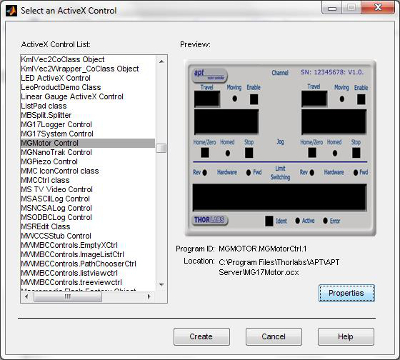
Figure 7.1 MATLABでActiveXコントロールにアクセスした様子
APTシステムソフトウェアはActiveXコントロールとセットで実装され、APTソフトウェアがインストールされるとActiveXコントロールがホストPCのコントロールライブラリに追加されます。通常、ActiveXコントロールはユーザーインターフェイスを有し、複数のプログラミング環境のうちの1つと通信します。複数のプログラミング環境下でActiveXコントロールを使用する際は、Microsoft®コンポーネントオブジェクトモデル(COM)を利用します。COMは、オブジェクトの作成時とは異なる環境下でも使用可能なオブジェクトとして実装するための標準的なバイナリインターフェイスです。つまり、内部の実装についての情報がなくてもオブジェクトを再利用することができます。Microsoft社のActiveXコントロールはコントロールコンテナを必要とするインプロセスのCOMサーバで、ActiveXコントロールをホストできるアプリケーションです。プログラミング環境や、MATLAB®、Visual C++、C#のような言語を使用してコントロールコンテナを作成できるため、目的に応じてActiveXコントロールと通信することができます。
MATLAB®
MATLAB figureウィンドウやSlinkink®モデルはコントロールコンテナの1例です。一般的な使い方では、MATLABでfigureウィンドウにActiveXコントロールを作成し、コントロールのプロパティ、メソッドおよびイベントを通じてこれを操作します。この場合、当社のAPT ActiveXコントロールはサーバとして、MATLABはクライアントとして動作します。また、グラフィカルユーザーインターフェイス(GUI)コンポーネントはAPT ActiveXコントロールとして実装されます。MATLABは、ActiveXオブジェクトを作成することによって、APT GUIコンポーネントを用いてハードウェアを制御することができます。MATLABおよびActiveXコントロールを当社のAPTポジショナと使用する場合の詳細については、こちらからご覧いただけます。
Visual C++
目的とする新しいC++プロジェクトを作成し、メインアプリケーションのダイアログボックスを表示させ、表示されたライブラリから必要なAPT ActiveXコントロールを選択します。Video 7.2と7.3では、APT ActiveXコントロールをVisual C++で動作させる方法や、カスタム仕様のポジショニングシーケンスのプログラミング方法をご覧いただけます。
C#
C#とAPT Serverを用いて始めるためのサンプルプログラムをご覧いただけます。各ActiveXコントロールの使用方法は、サンプルプロジェクトファイルのデモでご覧いただけます。ファイルはVisual Studioまたはその他の同様の開発パッケージで開くことができます。サンプルは関連する制御装置ごとに以下の4つのセクションに分かれています:モータ、NanoTrack、ピエゾ素子、クォドラントディテクタ。サンプルはこちらからダウンロードいただけます。
| Posted Comments: | |
Kareem Asham
(posted 2025-03-24 17:02:23.403) Hi, I am trying to use an older Apt brushless motor with labview 2025. Whenever I run the program, an error comes up detailing EnableHWchannel error where when there is a software call done to the driver, there is no response. However, I am able to control the driver and stage using Kinesis program. dnewnham
(posted 2025-04-11 04:49:27.0) Thank you for your inquiry I will reach out to you directly to discuss troubleshooting steps for you Hashim Ali
(posted 2024-02-01 19:06:59.117) Hi. I am trying to make labview program for nanomax 300 with APT Piezo controller BPC 203. I want to move my sample along lateral and axial axis using labview. Could you send me the exact labview program for nanomax 300. do'neill
(posted 2024-02-13 06:03:30.0) Thank you for reaching out. I will contact you directly with an example and to help with your application. Daniel E
(posted 2023-01-24 05:26:11.433) Hi. I am interested in creating a GUI interface with Labview to control 3 devices: 1 LTS and 2 KDC 101. The KDCs will use Z825B Stepper Motors to move each stage along X and Y axis.
I will like to know if the Motor2DScan.vi can be used to implement that and if yes, how do I configure it? JReeder
(posted 2023-01-25 11:34:00.0) Thanks for your enquiry. The example VIs such as Motor2DScan.vi are to enable you to get started with the functions and provide you with a starting point so you can get set up for your specific application quicker. The Motor2DScan VI shows a basic 2D raster scan using two motor controllers, not three. However adding in a third controller is the same as adding in a second controller, which this VI shows how to do. In order to get these examples configured, you will need to have installed the APT software and you will need to change the serial numbers to those of your devices. I would advise that you read through our documentation on how to set up these controls up in LabVIEW, further information can be found here: https://www.thorlabs.de/images/TabImages/GuideToLabVIEWandAPT.pdf Simon S.
(posted 2021-07-27 10:12:48.23) It seems like for the Linear Travel Stages the StartCtrl outputs a 0 (not indicating an error) even if the stage is not connected to the PC. I followed the guide on error handling and also had a look at the Basic and Intermediate Example VIs you kindly made available.
Because the method StartCtrl does not indicate an error, I wonder how can I catch the exception and avoid runtime-errors?
Thank you! DJayasuriya
(posted 2021-07-29 05:17:10.0) Thank you for your inquiry. We will get in touch with you directly to resolve your issue. Dmytro Afanasiev
(posted 2021-05-31 17:05:33.28) I have an issue with the programming APT LabView interface. Actually it works fine with a single motor but once I run two instances of the APT interfaces it crashes giving me a lot of errors. Can I actually in one LabView .vi control two devices and if it is so than how?
Thanks a lot for your answer! jcater
(posted 2021-06-02 07:10:15.0) Response from Jack at Thorlabs: Thank you for your feedback. You can use APT in LabVIEW to control multiple devices at once. You can create an ActiveX control for each individual device to control them individually, I will reach out to you with an example of how to do this. Emily R
(posted 2021-02-04 17:55:02.713) Hi, I'm using the MFF101 with LabVIEW and every time I run my code, LabVIEW crashes. I saw another comment which stated LabVIEW would crash if IChanID was not set to 0, but this happens as soon at it reaches the "StartCtrl" property node, before IChanID is even specified. Previously, I was able to control the flipper with the ATP User application, but now ATP User does not load up at all while the flipper is connected to my computer. If I disconnect the flipper, ATP User loads up fine. cwright
(posted 2021-02-05 11:12:19.0) Response from Charles at Thorlabs: Thank you for contacting us. We will reach out to you directly to help troubleshoot this. Gayatri Vasudevan Rajeswari
(posted 2020-12-07 18:00:33.017) I would like to align fiber to the photonic integrated circuit using BNT001/IR stage. I wanted to program in LABVIEW to move to the desired position automatically using APT module. Initially, I was planning to use APT Active X MG17Nanotrak to achieve this, but later I found it out that the MG17 Nanotrak does not have an inbuilt 'move' function to move the piezo actuator to the desired position. So I thought of MG17Piezo ActiveX for this, but I am not able to achieve proper communication between the software and hardware. Kindly let me know does MG17 Piezo ActiveX be communicated to BNT001/IR device. If not please suggest an alternative way to achieve it. cwright
(posted 2020-12-09 04:42:16.0) Response from Charles at Thorlabs: Thank you for your query. To communicate with the BNT001/IR one must use the MG17NanoTrack control, there is no 'move' command with the BNT001/IR as this is designed for an auto-alignment system. The piezo actuators will use the MG17Piezo control and the Piezo Inertial motors will use the MG17PZMotor control. To set the output voltage on the piezo actuator you can use the SetVoltOutput method. Setting the NanoTrack to 'Track' using the Track() function will automatically control the output voltage for the piezo actuators. Edit: it appears this request was misunderstood. The correct method to take is to use the SetCircHomePos method on the MG17NanoTrack control to move the circle around and hence set the piezo outputs. You should Latch the NanoTrak before doing this. xinxin xing
(posted 2020-10-30 13:24:03.727) Hi, I'm using KDC101 on LabVIEW 2017 (64-bit windows). I have two Z825B Stepper Motors and I need to move the stage in raster scan (one motor along X and other along Y) like X stage will move 8 mm while Y waits then Y moves for 0.5 mm then the process repeats until a specified area (e.g 64 mm^2) is covered. When I try to use the Motor2DScan.vi example download from Thorlabs, LabVIEW breaks down. Then I have to reinstall the LabVIEW software. It happens several times. Is that a problem with LabVIEW or with the controller? thanks for your help. cwright
(posted 2020-11-04 03:10:17.0) Response from Charles at Thorlabs: Hello and thank you for your query. While we have previously encountered an error which caused LabVIEW to crash, we have not heard of one which causes it to require reinstallation. We will reach out to you to get the details of your APT installation and to troubleshoot this with you. Update: The issue in this case was using the wrong channel number for the parameter "lChanID - the channel identifier". This channel ID should be 0 for single motor controllers. Spencer Nelson
(posted 2020-10-29 17:33:57.73) I'm interfacing to the APT ActiveX controller with LabWindows/CVI. In debug mode, I get an intermittent "Fatal Run-Time Error. Unknown source position, thread id 0x00002C48 A non-debuggable tread caused a 'General Protection"' fault at address 0x590AEF90." Was occurring occasionally, but now at least 4 out of 5 times after a power cycle on the linear stage. Any help would be appreciated. Thanks. cwright
(posted 2020-11-03 05:01:24.0) Response from Charles at Thorlabs: Hello Spencer and thank you for your query. While we have not been approached with this error before, and do not have any experience running LabWindows, we can see that this error has arisen and been addressed by NI. It appears to be an issue with how some versions of LabWindows load controls. We will reach out to you to discuss this and see if it solves your issue. Angeliki Vavladeli
(posted 2020-08-03 05:30:50.23) I am using Thorlabs APT software through LabVIEW, to control a stepper motor (3 channels BSC203). For this purpose, I had referred to Thorlabs' Guide to LabVIEW and APT. My project requires me to use APT with certain settings as default, therefore I need to modify the default settings. While it is possible to "save” and ''load’' the settings as a template in the APT software, I am not able to access this file (no prompt window appears to see filepath) in order to apply the same APT settings through LabVIEW, or to save settings through APT LAbVIEW program.
Do you know where this settings file is most likely located in my PC?
Or do you know how I can change and save/load APT settings through LabVIEW? DJayasuriya
(posted 2020-08-05 10:21:06.0) Thank you for your inquiry. You would be able to save the settings in APT and they get saved into the registry. The location its saved into is: Thorlabs >APT server> User. Please get in touch with us if directly if you have any have any questions. Wenquan Liu
(posted 2020-05-21 20:40:35.507) Hi, I am using a KBD101 to control a DDSM100(/M) stage through the LabView 2009 (fairly old, and the OS is Windows XP). Could you provide us with the APT 32-Bit Software for 32-Bit Windows XP system? Thanks a lot. DJayasuriya
(posted 2020-05-22 03:48:44.0) Thank you for your inquiry. Please have a look at this link to find APT 32-Bit Software for 32-Bit Windows:https://www.thorlabs.com/software_pages/ViewSoftwarePage.cfm?Code=Motion_Control&viewtab=0
If you have any other questions you can reach your local techsupport team on techsupport-cn@thorlabs.com DJayasuriya
(posted 2020-05-22 03:48:44.0) Thank you for your inquiry. Please have a look at this link to find APT 32-Bit Software for 32-Bit Windows:https://www.thorlabs.com/software_pages/ViewSoftwarePage.cfm?Code=Motion_Control&viewtab=0
If you have any other questions you can reach your local techsupport team on techsupport-cn@thorlabs.com Victor de Bar
(posted 2020-05-01 09:26:43.02) Hello Thorlabs,
Is it possible to simulate the Thorlabs Kinesis hardware in LabVIEW, is there a manual for this?
I know there is a Kinesis simulator tool but I cannot connect to the simulator through LabVIEW.
Unfortunately I do not have acces to the hardware at the moment so it would be really nice to check the code with the simulator.
I am using Kcube Stepper controller, Thorlabs, KST101 and a Microstepper stage, Thorlabs, LNR25ZFS
Kind regards,
Victor DJayasuriya
(posted 2020-05-04 04:00:46.0) Thank you for your inquiry. Yes we do have a simulator that works with Labview. I will get in touch with you directly to resolve your issue. 15652586760
(posted 2019-03-08 10:00:46.69) Hello, our LabView MG17motor's number is 123456 which is different from the number on the hardware . So the LabView cannot work even as the instructions you give. I hope you can give me some advice, thanks. rmiron
(posted 2019-03-12 08:47:00.0) Response from Radu at Thorlabs: This probably means that the stage's EEPROM has not been correctly programmed, in which case I apologise on behalf of Thorlabs. If that is the situation, you would simply have to set the serial number property in LabVIEW to 123456. I will contact you directly to check whether that is indeed the case and to help you run your virtual instrument. protap.mahanta
(posted 2019-02-06 12:46:20.31) Hi, I am trying to control Thorlab's BPC 303 controller using Labview. I am following the manual's guide to accomplish it, however, it shows the following error message:
A software call has been made to a control which is not currently communicating with any hardware! This may be because the control has not been started or wrong serial number or missing hardware!
I checked the controller is powered on, connected, serial no is right...Now, what should i cehck? Thanks! rmiron
(posted 2019-02-07 05:36:52.0) Response from Radu at Thorlabs: This error can indicate that there are problems with the USB communication, or that the nodes are not called in the correct order. Your local tech support team will help you troubleshoot your application if you send them over a screenshot of your VI. They might also be interested in which node raises the error and in whether the controller is visible in Device Manager. pmillho
(posted 2018-11-21 14:15:20.64) Hi there,
I'm wondering what version of LabVIEW (32-bit or 64-bit) your APT motor controller software works with?
We are using LTS300 and LTS150 stages, can these be controlled using 64-bit LabVIEW?
Thanks! rmiron
(posted 2018-11-22 05:57:52.0) Response from Radu at Thorlabs: APT must have the same bit-version as LabVIEW in order for the provided ActiveX Controls to be successfully inserted in a VI. Therefore, you require a 64-bit version of APT. arne
(posted 2018-10-09 13:48:16.167) Hi there,
I need to address and control Thorlabs "Rotation Stage with Resonant Piezoelectric Motor" ELL8K/M with LabVIEW. Is it possible to use the VIs provided here for a start. And which one would be the best. I guess the Piezo VIs, isn't it?
Thank you very much and best regard from the very south of Germany,
Arne Lüker, Ph.D. rmiron
(posted 2018-10-12 10:01:17.0) Response from Radu at Thorlabs: Thank you for raising this question Arne. It is possible to control Elliptec device from LabVIEW, but not through our APT or Kinesis software packages. You require the Elliptec software for this. Furthermore, because we have yet to release a 32-bit for 64-bit OS version of Elliptec, the bit-version of LabVIEW needs to match the bit-version of your OS. At the moment we don't have any tutorials on the website for how to use the Elliptec .NET assembly. We are looking to add some in the near future. I will contact you directly in order to provide you with a suitable example VI. s.j.goodband
(posted 2018-09-24 09:15:28.923) Hi,
I am using a KDC101 to control a Z825B stage.
I have written a labview script which gets the motor to step forward at a known speed (and known step size) - but I can't find a way to get it to step back as it won't allow negative steps. Can you think of any way to do this? rmiron
(posted 2018-09-24 11:35:47.0) Response from Radu at Thorlabs: I will contact you directly in order to offer assistance. I think the solution lies in using MoveRelative() methods instead of Jog(). shenwb
(posted 2018-08-03 21:24:13.66) Hi,
I am using Thorlabs KDC101 to control MTS50. How could I change the parameter like loop times and step length in your intermediate VIs examples?
Thank you! rmiron
(posted 2018-08-06 10:43:09.0) Response from Radu at Thorlabs: If you look into the block diagram, you will see two controls labelled "Scale" and "Num of Steps". If you right-click on them and choose the "Show Control" option, they will reveal themselves on the front panel. By changing the value fed into "Scale" you will change the step length and by changing the value taken by "Num of Steps" you will change the loop times. I will contact you directly in case further assistance is required. djoyce
(posted 2018-06-11 15:24:28.997) Have a Thorlabs nano rotation stage on a BSC201. I also have LabView 8.5-- fairly old (10 yr)
The LabView software won't seem to load the motor control-- a big blank area appears.
Is the LabView version too old? rmiron
(posted 2018-06-15 07:24:48.0) Response from Radu at Thorlabs: Unless you already configured LabVIEW to use the 4.0 version of the Common Language Runtime, this behaviour is to be expected. In order to fix this issue, I suggest you follow the steps listed here: https://knowledge.ni.com/KnowledgeArticleDetails?id=kA00Z0000019LDcSAM
If adding that configuration file does not fix the problem, you might have compatibility issues because your operating system is too new. According to National Instruments, Windows Vista is the latest OS which is compatible with LabVIEW 8.5. peatkinson2
(posted 2018-04-23 09:29:10.417) Hi,
I have a Thorlabs stepper motor K10CR1 and I'm trying to run it in labview. In APT User I can control the position accuracy to 0.01 degrees however using Active X to operate the motor in labview and the basic "move relative" and "move absolute" I am only able to control the position to the nearest degree? How might this be overcome in my labview programming?
Kind regards,
Peggy Atkinson (assistant researcher Lund University) rmiron
(posted 2018-04-26 06:01:11.0) Response from Radu at Thorlabs: Dear Peggy, I am surprised to hear this given that the MoveAbsoluteRot and the SetAbsMovePos methods are meant to take real numbers as parameters specifying the position. The same applies to relative movements. Perhaps the numeric controls that you use to feed those parameters have integer representations. If that is the case, then right-clicking on them and selecting Representations\Double Precision, should fix this issue. If that is not the case, please contact one of our technical support teams. runarplu
(posted 2017-01-20 04:35:38.513) Hi,
I have a Thorlabs stepper motor and the BSC103 controller currently running on the 32bit APT-software. I am using the sequencer and it works just fine. One question though:
- Is there an easy way to import the stage-position from this software directly into LabView without making a VI for the stage (https://www.thorlabs.com/images/TabImages/GuideToLabVIEWandAPT.pdf)?
- Can the stage movement history easily be logged in a .txt-file (updates continuously as new positions occur)?
Best regards
. . . . . . . . . . . . . . . . . . . . . . . . . . . . . . . . . . . .
Runar P. Dahl-Hansen
PhD Candidate
Dept. of Electronics and Telecom.
Norwegian University of Science and Technology (NTNU)
Trondheim, Norway
Mobile: +47 926 54821
www.ntnu.no
. . . . . . . . . . . . . . . . . . . . . . . . . . . . . . . . . . . . bhallewell
(posted 2017-02-01 06:26:20.0) Response from Ben at Thorlabs: Thank you for your question here. An ActiveX object will need to be added into your VI in order to make use of the ActiveX methods which will control & enable you to access information from the stage. When you add in the ActiveX object, a GUI is built. It is possible to grey out & re-size this UI & title font within LabVIEW Front Panel however this unfortunately needs to exist. In terms of outputting positions to a text file, this can be done through use of the 'Write to Text File' function from the Programming > 'File I/O' palette within the LabVIEW block diagram. Through use of an iterative loop, you can open a text file, within each iteration write to text file, what is output from the GetPosition method. Some of the following may be of use to you.
https://www.thorlabs.com/images/TabImages/GuideToLabVIEWandAPT.pdf
https://zone.ni.com/reference/en-XX/help/371361H-01/glang/write_characters_to_file/
https://forums.ni.com/t5/LabVIEW/how-continuously-write-data-to-a-txt-file/td-p/1846549 |
 Products Home
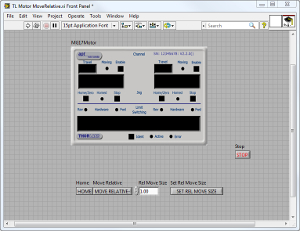
 APT™とLabVIEW™