半導体光増幅器、Cバンド(1550nm)、偏光依存型(BOA)および偏光無依存型(SOA)
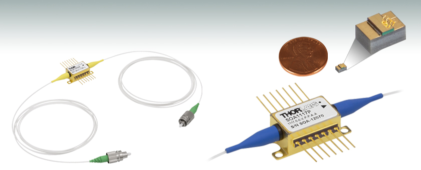
- Compact Optical Amplifier in Butterfly Package
- Low Noise, Broad, Flat Optical Bandwidth, High Saturation Power (>15 dBm)
- Polarization-Independent and Polarization-Maintaining Versions
BOA1004S
BOA with SM Fiber and FC/APC Connectors
BOA1007C
Actual Size Compared to a U.S. Penny
SOA1117P
SOA with PM Fiber and FC/APC Connectors, Close-up of Butterfly Package Shown

Please Wait
| Optical Amplifier Selection Guide |
|---|
| 780 - 795 nm BOAs |
| 830 nm BOAs |
| 930 nm BOAs |
| 980 nm BOAs |
| 1050 nm BOAs |
| 1210 nm BOAs |
| 1250 nm BOAs |
| O-Band (1285 - 1350 nm) BOAs |
| E-Band (1410 nm) BOAs |
| C-Band (1550 nm) BOAs and SOAs |
| L-Band (1590 - 1625 nm) BOAs |
| 1685 nm BOAs |
| 1700 nm BOAs |
お問い合わせください。
Click to Enlarge
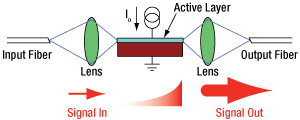
電流がリッジ導波路に印加されると、励起状態の電子が入射光の刺激を受けます。これにより光子が複製され、信号利得が得られます。
特長
- 半導体光増幅器、偏光依存型(BOA)
- 1つの偏光状態のみを増幅
- FC/APCコネクタ付きの1.5 m長のシングルモードまたは偏波保持ファイバーピグテール
- サブマウントまたはヒートシンクを取り付けた自由空間入出力用の半導体光増幅器チップもご用意
- 一般的な用途:変調、MUX/DeMUXの挿入損失の補償、光シャッタ
- 半導体光増幅器、偏光無依存型(SOA)
- すべての偏光状態を増幅
- FC/APCコネクタ付きの1.5 m長のシングルモードまたは偏波保持ファイバーピグテール
- 一般的な用途:インライン増幅器、ディテクタ用プリアンプ、高速光スイッチ (切替速度およそ1 ns)
半導体光増幅器は、シングルパスの進行波増幅器で、単色信号あるいは多波長信号の両方において性能を発揮します。偏光依存型半導体光増幅器(BOA)は1つの偏光状態のみを増幅するので、入力光の偏光状態が分かっている条件での使用に適しています。これに対して入力信号の偏光状態が不明の場合や変動する用途では、偏光無依存型半導体光増幅器(SOA)が必要となります。しかしながら利得、雑音、バンド幅や飽和出力強度の仕様は、偏光依存型(BOA)の方が偏光無依存型(SOA)と比較して優れています。これは偏光無依存型(SOA)では偏光無依存の特性を付与している設計により上記特性が犠牲になっているためです。
当社では結合損失が低いファイバー出力型の半導体光増幅器(BOAおよびSOA)のほかにも、サブマウント(C)またはヒートシンク(H)に取り付けた半導体光増幅器チップ(偏光依存型BOA)もご用意しております。損失の典型値はファイバからチップ、そしてチップからファイバそれぞれの結合において1.5~2.5 dBです。この結合損失は、総利得、雑音指数(NF)、および飽和出力強度(Psat)に影響を及ぼします。増幅によって得られる利得が損失を上回ったとしても、これらの損失はデバイスの性能に重要な影響を与えます。例えば、入力結合効率が1 dB減少した場合、雑音指数は1 dB増加します。これに対して出力結合が1 dB減少した場合は、飽和出力強度も1 dB減少します。
マウントとドライバについて
これらのバタフライパッケージは電流ドライバとTECドライバが内蔵されている半導体レーザーマウント付き電源CLD1015に対応します。こちらの半導体光増幅器をCLD1015で駆動する際は、タイプ1のピン配列の向きでご使用ください。また、こちらはレーザーマウントLM14TSとLM14S2にも対応しますが、マウントを使用することにより、当社の半導体レーザ、温度コントローラ、半導体レーザ/TECコントローラをご使用いただけます。5 °C以上の温度変動のある環境下においては、半導体レーザーのケース温度をアクティブ制御し、増幅器の波長と出力パワーを安定させるマウントLM14TSのご使用をお勧めいたします。
中心波長について
光増幅器などの広帯域半導体デバイスにおける自然放射光増幅(ASE)スペクトルの中心波長(CWL)は、ロット毎にバラつきがある可能性があります。各モデルのCWLの公差については、「仕様」タブをご参照ください。特定のASE中心波長をご要望の場合、現在ご提供可能なロットの中心波長についての情報をご提供できますので、当社までお問い合わせください。
偏光依存型半導体光増幅器(BOA)、バタフライパッケージ
| Item # | BOA1004S and BOA1004P | BOA1550S and BOA1550P | |||||
|---|---|---|---|---|---|---|---|
| Parametera | Symbol | Min | Typical | Max | Min | Typical | Max |
| Operating Current | IOP | - | 600 mA | 750 mA | - | 900 mA | 950 mA |
| Center Wavelength | λC | 1530 nm | 1550 nm | 1570 nm | 1530 nmb | 1550 nmb | 1580 nmb |
| ASE Optical 3 dB Bandwidth | BW | 80 nm | 85 nm | - | 95 nm | 105 nm | - |
| Saturation Output Powerc (@ -3 dB) | PSAT | 13 dBm | 15 dBm | - | 17 dBmd,e | 18 dBmd,e | - |
| Small Signal Gain (@ PIN = -20 dBm) | G | 23 dBd | 27 dBd | - | 24 dBd,e | 27 dBd,e | - |
| Gain Ripple (RMS)e | δG | - | 0.05 dB | 0.3 dB | - | 0.04 dB | 0.3 dB |
| Polarization Extinction Ratio | PER | - | 18 dB | - | - | 18 dBf | - |
| Noise Figure | NF | - | 7.5 dB | 9 dB | - | 8.5 dBd,e | 9.5 dBd,e |
| Forward Voltage | VF | - | 1.3 V | 1.6 V | - | 1.6 V | 2.1 V |
| Chip Length | - | - | 1.5 mm | - | - | 1.5 mm | - |
| Waveguide Refractive Index | - | - | 3.2 | - | - | - | - |
| TEC Operation (Typical/Max @ TCASE = 25 °C/70 °C) | |||||||
| TEC Current | ITEC | - | 0.13 A | 1.5 A | - | 0.55 A | 1.5 A |
| TEC Voltage | VTEC | - | 0.28 V | 4.0 V | - | 0.70 V | 4.0 V |
| Thermistor Resistance | RTH | - | 10 kΩ | - | - | 10 kΩ | - |
偏光無依存型半導体光増幅(SOA)、バタフライパッケージ
| Item # | SOA1013S | SOA1117S and SOA1117P | |||||
|---|---|---|---|---|---|---|---|
| Parameter | Symbol | Min | Typical | Max | Min | Typical | Max |
| Operating Current | IOP | - | 500 mA | 750 mA | - | 500 mA | 600 mA |
| Operating Wavelength Range | - | 1528 nm | - | 1562 nm | 1528 nm | - | 1562 nm |
| Center Wavelength | λC | - | 1500 nma | - | - | 1550 nm | - |
| Saturation Output Powerb (@ -3 dB) | PSAT | 12 dBm | 14 dBm | - | 6 dBmc | 9 dBmc | - |
| Small Signal Gain (Over C-Band @ Pin = -20 dBm) | G | 10 dB | 13 dB | - | 15 dB | 20 dB | - |
| Gain Flatness (Over C-Band @ Pin = -20 dBm) | ΔG | - | 5 dB | 7 dB | - | - | - |
| Gain Ripple (p-p) @ IOP, λC | δG | - | 0.1 dB | 0.5 dB | - | 0.2 dB | 0.5 dB |
| Polarization Dependent Gain | PDG | - | 1.0 dB | 1.8 dB | - | 1 dB | 2.5 dB |
| Noise Figure | NF | - | 8 dB | 9.5 dB | - | 10 dB | 11.5 dB |
| Forward Voltage | VF | - | 1.6 V | 1.8 V | - | 1.4 V | 2.0 V |
| Chip Length | - | - | 1.5 mm | - | - | 1.0 mm | - |
| Waveguide Refractive Index | - | - | 3.2 | - | - | 3.2 | - |
| TEC Operation (Typical/Max @ TCASE = 25/70 °C) | |||||||
| TEC Current | ITEC | - | 0.23 A | 1.5 A | - | 0.2 A | 1.5 A |
| TEC Voltage | VTEC | - | 0.5 V | 4.0 V | - | 0.4 V | 4.0 V |
| Thermistor Resistance | RTH | - | 10 kΩ | - | - | 10 kΩ | - |
偏光依存型半導体光増幅器(BOA)チップ
| Item # | BOA1007C and BOA1007H | |||
|---|---|---|---|---|
| Parameter | Symbol | Min | Typical | Max |
| Operating Current | IOP | - | 600 mA | 750 mA |
| Central Wavelength | λC | 1530 nm | 1550 nm | 1580 nm |
| Optical 3 dB Bandwidth | BW | 80 nm | 85 nm | - |
| Saturation Output Powera (@ -3 dB) | PSAT | 15 dBm | 18 dBm | - |
| Small Signal Gain (@ PIN = -20 dBm, λ = 1550 nm) | G | 26 dB | 30 dB | - |
| Gain Ripple (RMS) @ IOP | δG | - | 0.05 dB | 0.3 dB |
| Polarization Extinction Ratio | PER | - | 18 dB | - |
| Chip Noise Figure | NF | - | 6.0 dB | 8.0 dB |
| Forward Voltage | VF | - | 1.3 V | 1.6 V |
| Chip Length | L | - | 1.5 mm | - |
| Waveguide Refractive Index | - | 3.2 | - | |
| Lateral Beam Exit Angle | ΘEXT | - | 19.5° | - |
| Beam Divergence Angle (FWHM) | ||||
| Transverse | ΘT | 26° | 34° | 42° |
| Lateral | ΘL | 10° | 14° | 30° |
Click to Enlarge
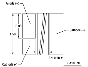
図1:BOA1007Cの図(上面)。チップのアノードとカソードが示されています。なおBOA1007Hは同様のチップ構造をしていますので、アノードとカソードの位置も同様です。
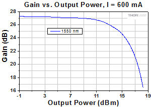
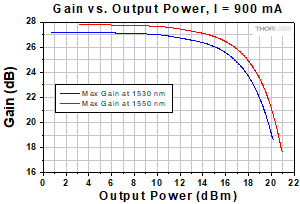
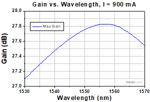
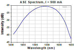
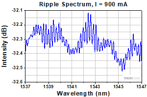
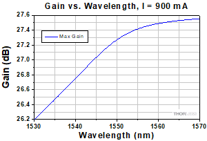
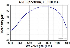
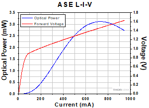
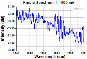
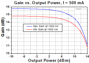
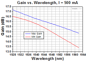
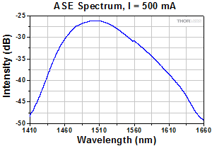
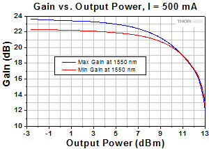
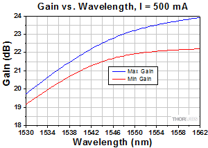
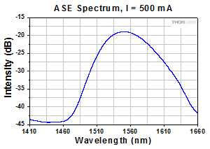
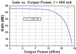
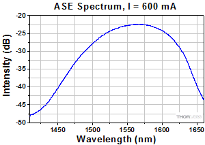
注:すべてのグラフは典型的な性能を示しており、ユニットにより「仕様」タブ内の仕様値の範囲内で若干異なる可能性があります。
BOA1004S&BOA1004Pのグラフ
BOA1550Sのグラフ
BOA1550Pのグラフ
SOA1013Sのグラフ
SOA1117S&SOA1117Pのグラフ
BOA1007C&BOA1007Hのグラフ
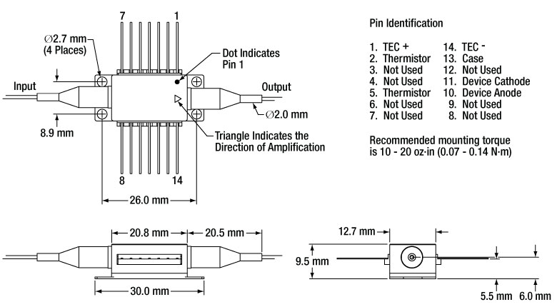
バタフライ型パッケージのピン配置図と図面
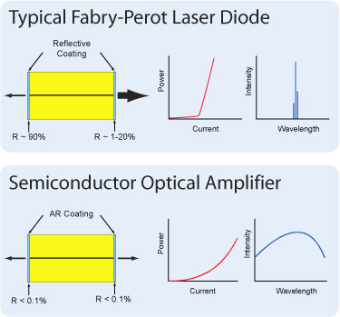
半導体光増幅器(BOAおよびSOA)は、シングルパスの進行波増幅器で、単色信号あるいは多波長信号の両方において性能を発揮します。偏光依存型半導体光増幅器(BOA)は1つの偏光状態のみを増幅するので、入力光の偏光状態が分かっている条件での使用に適しています。これに対して入力信号の偏光状態が不明の場合や変動する用途では、偏光無依存型半導体光増幅器(SOA)が必要となります。しかしながら利得、雑音、バンド幅や飽和出力強度の仕様は、偏光依存型(BOA)の方が偏光無依存型(SOA)と比較して優れています。これは偏光無依存型(SOA)では偏光無依存の特性を付与している設計により上記特性が犠牲になっているためです。
半導体光増幅器はファブリペローレーザと似た設計ですが、相違しているのは、ファブリペローレーザでは、半導体チップの両端面に反射コーティングが施されている点です。両端の反射面からの戻り光が共振器として機能し、レーザ発振が生じます。半導体光増幅器では、半導体チップの両端面に反射防止(AR)コーティングが施されています。これによりチップに戻る光は制限されるので、レーザ発振は生じません。
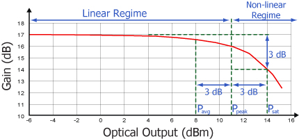
全ての増幅器に共通する典型的な特性ですが、半導体光増幅器にも2つの動作領域があります。1つは線形でフラットな一定利得の領域で、もう1つは非線形で出力が飽和する領域です。変調信号を増幅するのに使用されるのは一般に線形領域で、そこではパターン効果、マルチチャンネルクロストーク、エルビウムドープファイバ増幅器(EDFA)でも見られる過度応答といった問題が発生しません。非線形領域は、半導体利得媒質の高非線形性(相互利得変調や相互位相変調)を活かして、波長変換、光3R再生、ヘッダ認識、その他の高速光信号処理などに利用されます。
CW入力信号では、増幅器が生成できるパワーの合計は飽和出力(Psat)のパラメータで決定されます。Psatは、小信号利得が3 dB低くなる出力で定義されます。一般的に出力可能な最大のCWパワーは、飽和出力よりもおよそ3 dB高くなります。
| Posted Comments: | |
William Swann
(posted 2024-10-18 13:51:24.067) Hello Thorlabs, We would like to know if your SOA1117S can operate bi-directionally, that is will it simultaneously amplify a signal entering the output and exiting the input along with a signal entering the input and exiting the output? If it cannot operate this way, can you comment as to why not? Thank you. jpolaris
(posted 2024-10-22 08:15:47.0) Thank you for contacting Thorlabs. These SOAs are built with a symmetric structure so they can be used bidirectionally and the gain will be the same. However, if it is operated backwards, it is likely that the saturation power and the noise figure will deviate from their specified values because it is common for the coupling efficiencies of the input and output fibers to be different. user
(posted 2022-08-16 11:49:50.877) i'm using BOA1004P on our project and i want to operate BOA1004P on 35°C. So i want to know BOA1004P's thermistor temperature coefficient or equation.
Thank you. ksosnowski
(posted 2022-08-23 01:17:38.0) Thanks for reaching out to Thorlabs. We use the same 10kOhm thermistor in most of our butterfly devices. The Steinhart-Hart coefficients for this are as follows: A= 1.129241E-03, B= 2.341077E-04, C= 8.775468E-08. user
(posted 2021-02-17 08:04:44.963) Dear Sir or Madam,
I could not find following information in the spec sheet:
(1) FC/APC connector key is aligned to slow or fast axis?
(2) Amplification is really aligned to fast axis as commented in Feedback section? (slow axis typically is better suited for PM stability and wide spread standard)
(3) What is the absorption value of the BOA when short circuit? Preferably high, in range 40...50dB?
Thank you very much YLohia
(posted 2021-03-12 04:47:46.0) Hello, thank you for contacting Thorlabs. (1) It is aligned to the slow-axis (2) It is aligned to the slow axis, not the fast axis (3) Unfortunately, we don’t have spec of absorption value for BOA1004P when no current is applied. If you have a key requirement for it, the BOA1004PXS would be more suitable since it has an isolation spec of > 40 dB when no current is applied. alexey Kokhanovskiy
(posted 2020-12-01 00:26:02.43) Dear Sir/Mme
We have purchased BOA1004P. What state of the polarization does BOA amplifies? That goes along fast or slow axis of PM fiber?
With respect,
Alexey Kokhanovskiy YLohia
(posted 2020-12-01 10:20:21.0) Hello Alexey, thank you for contacting Thorlabs. The BOA amplifies the polarization state along the slow axis of the fiber. Vasili Savitski
(posted 2020-04-07 05:11:46.033) Hi. Could you please give some numbers on the rise time of your BOA and SOA working in pulsed regime? Thank you. YLohia
(posted 2020-04-07 09:24:54.0) Hello, thank you for contacting Thorlabs. We have seen rise times on the order of hundreds of picoseconds for these BOAs in the past. Unfortunately, we do not have a formal rise time spec for these. I have reached out to you directly to discuss this further. DH Lee
(posted 2019-08-08 19:24:22.277) Can you show me the width and height of the ridge waveguide? YLohia
(posted 2019-08-09 09:56:59.0) Hello, thank you for contacting Thorlabs. Unfortunately, we cannot share this information as it is proprietary. We do, however, post the chip length, refractive index, and transverse/lateral beam divergence angles for the BOA1007C (see Specs tab for more information). yedukondalu patha
(posted 2019-05-16 08:09:06.867) Could you please send the manual, how to operate SOA1117S.
Thanks,
Yedukondalu P YLohia
(posted 2019-05-16 09:02:47.0) Hello Yedukondalu, thank you for contacting Thorlabs. Unfortunately, we do not offer a manual for this as the operation is very similar to that of a regular butterfly pigtail laser diode. I have reached out to you directly to discuss your application further and offer any assistance I can. kimyeonhwa1006
(posted 2018-10-15 21:07:20.387) Hi, I have a question for SOA graphs. I'm just wondering that the reason why the SOA 1013S and SOA1117S has different tendency according to Gain vs wavelength.
The graph of SOA 1013S in appendix tends to be decreased while that of SOA 1117S tends to be increased. I'm waiting for your reply. Thank you. YLohia
(posted 2018-10-19 12:08:41.0) Hello, thank you for contacting Thorlabs. The reason is that the peak of the ASE for SOA1013S happens at ~1500-1510 and that of the SOA1117S is at ~1550nm. Thus, based on the 1528-1562nm (C-band) region shown in the plots in question, the plot decreases for SOA1013S and increases for SOA1117S. Both of SOA1013S and SOA1117S are for C-band applications and we only test gain across this window. For the SOA1013S, which is marketed as a linear device (due to its high saturation power), we intentionally set peak gain wavelength at ~1500nm to obtain higher saturation power in the C-band. The saturation power tends to be higher on the longer wavelength side of the peak. kyeongpyo.lee
(posted 2018-09-19 05:10:10.58) I was testing the small signal gain by using BOA1007H, and I found that whatever the input power is (i.e. -50dBm or -20dBm) its amplified output is fixed at about -13dBm for 200mA current supply. I cannot understand this situation. Is it possible to do so? YLohia
(posted 2018-09-25 10:05:02.0) Hello, thank you for contacting Thorlabs. Please note that the performance of the BOA is highly dependent on its junction temperature and, thus, the unit should be used under properly temperature controlled environments. The BOA1007H will already start to produce gain (around 10-20dB) even with a 200mA drive current at 1550nm. It is quite likely that your input coupling efficiency to the BOA is not high enough, which would imply that the chip is not receiving enough light to amplify. The measured power then will be the BOA's ASE power itself, which can be around 5mW at 500-600mA of drive current. This is the fixed output you are seeing at these low input power levels. If you find that the power of your signal of interest is not high enough compared to the ASE, you may want to use spectral filters to attenuate the ASE signal. FBH1550-12 or FB1550-12 would be good choices to look into for the 1550nm center wavelength. mdrolet
(posted 2018-09-09 22:39:48.94) Hi, Do you have any graph showing amplification in pulsed regime?
Thanks,
Mathieu YLohia
(posted 2018-09-17 02:22:57.0) Hello Mathieu, thank you for contacting Thorlabs. Based on our discussion, your 150ns pulse width with 40 kHz rep rate supplied to this SOA will be perfectly fine, assuming that you use appropriate drivers/mounts. I have reached out to you directly with an eye diagram for an informal test we performed on one of our SOAs in the past/ jchg2758
(posted 2018-08-27 07:28:15.16) Can I know the general recovery time of those c-band SOAs? I want to know how fast pulse train could be applied to this amplifier.
Thanks. YLohia
(posted 2018-08-27 10:53:12.0) Thank you for contacting Thorlabs. SOA1117S gain recovery time is not a parameter that we specify or measure, but we expect it to be in the 300-500 ps range (potentially on the faster side). robert.supe
(posted 2017-10-02 10:13:51.683) in regards to product BOA1007C. We have several units and the height of each chip varies greatly. from 905um to 765um. I am unable to locate a height specification or tolerance on any of the data sheet provided on the website for the product. In order to proceed with our product development we need to know what the tolerances and specifications are for this product. Are there any which can be provided? tfrisch
(posted 2017-10-02 06:22:35.0) Hello, thank you for contacting Thorlabs. We will reach out to you directly to discuss these tolerances. hvdbrom
(posted 2015-12-15 17:24:51.02) Is this amplifier meant for CW or for digital signals? We need to amplify digital signals with pulse repetition rate of 10 Gb/s or 20 Gb/s. besembeson
(posted 2015-12-16 09:52:24.0) Response from Bweh at Thorlabs USA: Yes these can amplify a 10Gb/s or 20Gb/s modulated optical input as well as cw. In fact, the original application of the SOA design was a telecom alternative to EDFAs. However, the peak power levels will be limited to the cw saturation power. bdada
(posted 2011-09-09 11:09:00.0) Response from Buki at Thorlabs:
Thank you for using our Feedback tool. We apologize for not providing the drawing for the BOA1007H on our website. We will add it shortly. In the meantime, please refer to SAF1093H, which has the same mechanical drawing as the BOA1007H.
You can access the drawing on the right side of the SAF1093H product page linked below.
http://www.thorlabs.com/thorProduct.cfm?partNumber=SAF1093H jikim
(posted 2011-09-09 11:34:06.0) I would like to ask the mechanical dimensions of a BOA1007H. Before ordering such parameters are important for the design of our experiment. Thanks in advance. jjurado
(posted 2011-05-18 13:08:00.0) Response from Javier at Thorlabs to jikim: Thank you very much for contacting us. You are correct, since SOA is polarization dependent, the gain at fix current and wavelength will vary if the polarization state of the input changes. So, the maximum and minimum gain curves just describe the window of gain changes vs. polarization state. The difference between the max. and min, gain values correspond, then, to the polarization dependent gain (PDG) spec in the Specs tab. jikim
(posted 2011-05-18 15:00:18.0) In the performance plots of a SOA1013S, the maximum and minimum gain are shown. What does it mean? Are they the gains for different input polarizations, i.e. for TM and TE modes? Thorlabs
(posted 2010-08-26 14:54:46.0) Response from Javier at Thorlabs to jikim: The chip lengths for all our SOA/BOAs is 1.5 mm, except for the SOA1117, which has a length = 1.0 mm. I will contact you directly regarding the refractive index, since this information is not currently readily available. jikim
(posted 2010-08-26 10:58:25.0) Could you specify the length of the chip and its refractive index at 1550 nm? Adam
(posted 2010-04-23 12:15:21.0) A response from Adam at Thorlabs to jikim: I apologize for the confusion. The fiber to chip loss is 2.5dB and the chip to fiber loss is also 2.5dB. The total dB loss from fiber to fiber is 5dB. jikim
(posted 2010-04-23 09:00:15.0) Do you mean that fiber-to-chip loss is 2.5 dB and chip-to-fiber loss is also 2.5 dB? Or the loss of each side consisting of a surface of the chip and a fiber? Adam
(posted 2010-04-20 16:44:21.0) A response from Adam at Thorlabs to Jikim. The coupling losses at each side is 2.5dB. jikim
(posted 2010-04-20 10:38:13.0) Dear Thorlabs,
I have a simple question on a fibre-coupled BOA (BOA1004S). In this device, a pair of fibers is connected. Thus, there should be a certain amount of the coupling losses, e.g. fiber to the chip and chip to the fiber. Could you let me know such coupling losses? They are very important parameter in my laser system.
And Im looking forward to hearing from you soon.
Best Regards,
Jae-Ihn Kim
===============================================
Dr. Jae-Ihn Kim
- Scientific Assistant -
Technische Universitaet Kaiserslautern
Fachbereich Physik
Erwin-Schroedinger-Str.
(Postfach 3049)
67653 Kaiserslautern - Germany
Tel: (49) - 631 - 205 - 2319
Fax: (49) - 631 - 205 - 3903
http://www.physik.uni-kl.de/bergmann/
=============================================== Adam
(posted 2010-03-18 16:56:29.0) A response from Adam at Thorlabs to Sema: Previously, Covega has produced BOAs at this range, 1060nm. Thorlabs Quantum Electronics is planning on releasing a similar BOA in the next couple months. Will this work? At this time, there are no plans for the release of a SOA at this wavelength range, but if we can get more information about your application, I can suggest this as a new product idea. That being said, do you need a BOA or a SOA? Previously, most of our customer at this wavelength were either (1) making a laser for OCT or (2) amplifying 1064nm seed laser-- both of which a BOA is better suited than an SOA. I will email you to get more information for your application so we can suggest the most suitable product. sema
(posted 2010-03-18 10:20:02.0) Covega also used to produce SOAs for 1060 nm. Are these devices still available? |

- 1つの偏光状態のみを増幅
- FC/APCコネクタ付きの1.5 m長のシングルモードまたは偏波保持ファイバーピグテール
- 一般的な用途:変調、トランスミットMUX/DeMUXの挿入損失の補償、光シャッタ
偏光依存型半導体光増幅器(BOA)は、高効率のInP/InGaAsP多重量子井戸(MQW)構造です。上の概略図でもご覧いただけるように、増幅器の入出力光は、光増幅器のチップ上の信頼性の高いリッジ導波路に結合されています。Cバンドの偏光依存型半導体光増幅器(BOA)は標準的な14ピンバタフライ型パッケージに内蔵され、 FC/APCコネクタ付きのシングルモードファイバまたは偏波保持ファイバピグテールが付いています。すべての偏波保持ファイバーピグテール付きのモデルでは、コネクタのキーはファイバのスロー軸にアライメントされています。入力部または出力部、あるいは入出力部両方に偏波保持型アイソレータを取り付けた製品もご提供可能です(構成により仕様が異なる場合があります)。ご注文は当社までご連絡ください。
| Item #a | Center Wavelength | 3 dB Bandwidth | Saturated Output Power (@ -3 dB)b | Small Signal Gain (@ Pin = -20 dBm) | Noise Figure | Fiber Type | Connector Types |
|---|---|---|---|---|---|---|---|
| BOA1004S | 1550 nm | 85 nm | 15 dBm | 27 dBd | 7.5 dB | SM Fiber | FC/APC |
| BOA1004P | PM Fiber | ||||||
| BOA1550S | 1550 nmc | 105 nm | 18 dBmd,e | 27 dBd,e | 8.5 dB | SM Fiber | |
| BOA1550P | PM Fiber |

- すべての偏光状態を増幅
- FC/APCコネクタ付きの1.5 m長のシングルモードまたは偏波保持ファイバーピグテール
- 一般的な用途:インライン増幅器、ディテクタ用プリアンプ、高速光スイッチ(切替速度およそ1 ns)
半導体光増幅器(SOA)は偏光無依存なので、全ての偏光状態において光を増幅します。これらのデバイスは、インライン増幅器として適しています。先進のエピテキシャルウェハ成長技術とオプトエレクトロニクスパッケージング技術を利用して、広いスペクトル帯域で高い飽和出力強度、低雑音と高利得を実現しています。これらのデバイスは、業界標準の14ピンバタフライ型パッケージ入りで、FC/APCコネクタ付きのシングルモードファイバまたは偏波保持ファイバーピグテール入出力となっています。すべての偏波保持ファイバーピグテール付きのモデルでは、コネクタのキーはファイバのスロー軸にアライメントされています。この製品にはアイソレータは付属していませんが、偏光無依存型アイソレータを入力部または出力部、あるいは入出力部両方に取り付けた製品もご提供可能です。ご注文は当社までご連絡ください。
| Item #a | Center Wavelength | 3 dB Bandwidth | Saturated Output Power (@ -3 dB) | Small Signal Gain (@ Pin = -20 dBm) | Noise Figure | Fiber Type | Connector Type |
|---|---|---|---|---|---|---|---|
| SOA1013S | 1500 nmb | - | 14 dBm | 13 dB | 8.0 dB | SM Fiber | FC/APC |
| SOA1117S | 9 dBm | 20 dB | 10.0 dB | ||||
| SOA1117P | PM Fiber |
 Products Home




 ズーム
ズーム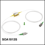

 Cバンド半導体光増幅器(SOA、BOA)