 Products Home
OCT用コモンパス干渉計モジュール
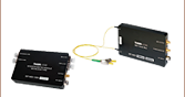
INT-COM-1300
- Common-Path Interferometer
- Balanced Detection
- Low Insertion Loss


Please Wait
| Item # | INT-COM-1300 |
|---|---|
| Wavelength Range | 1250 - 1350 nm |
| Insertion Loss: 1300 nm IN to Probea | < 1.5 dB (Typ), 2.3 dB (Max) |
| Insertion Loss: 1300 nm IN to VOA INa | < 17 dB (Typ), 20 dB (Max) |
| Insertion Loss: 660 nm IN to Probe Porta | < 2 dB (Typ), 4 dB (Max) |
| Output Bandwidth (3 dB) | DC - 15 MHz |
| Saturation Powerb | 70 uW @ 1300 nm |
| Maximum Input Power (Damage Threshold)b | 20 mW |
特長
- 低い挿入損失
- 平坦な波長特性
- アクティブエイリアシングフィルタ付きの差分ディテクタ組込製品
- アライメント用のガイド光(660 nm)の入力ポート
- コンパクト設計で電源付属
この干渉計モジュールINT-COM-1300は、周波数掃引光源OCTシステム内でコモンパスOCT用途として使用するために設計されています。 この製品は、光ファイバのネットワークと、外部のコモンパス干渉計プローブとの接続に用いられますが、 内部で使用されているカプラは、平坦な波長特性と偏光依存性の非常に低い結合損失を持つように設計されています。 内蔵の高利得差分ディテクタには、アクティブエイリアシングフィルタが有り、デジタルフリンジ信号におけるエイリアシング周波数の生成を低減するので、画像品質が向上します。
このモジュールは使いやすい設計で、FC/APC(斜め研磨)ファイバーアダプタが取り付けられています。 アライメントを簡単にするために、660 nmのガイド光用の入力ポートが付け加えられており、周波数掃引レーザ光源(1300 nm)とアライメント用レー ザ(660 nm)を結合するために設計されたWDMカプラが内蔵されています。
干渉計INT-COM-1300の仕様
| Item # | INT-COM-1300 |
|---|---|
| Optical | |
| Wavelength Range | 1250 - 1350 nm |
| Fiber Type | Corning SMF-28e |
| Fiber Port | FC/APC |
| Insertion Loss: 1300 nm IN to Probea | < 1.5 dB (Typ), 2.3 dB (Max) |
| Insertion Loss: 1300 nm IN to VOA INa | < 17 dB (Typ), 20 dB (Max) |
| Insertion Loss: 660 nm IN to Probe Porta | < 2 dB (Typ), 4 dB (Max) |
| Electrical | |
| Detector Material/Type | InGaAs |
| Detector Wavelength Range | 800 - 1700 nm |
| Maximum Responsivity (Typical) | 1.0 A/W |
| Output Bandwidth (3 dB) | DC - 15 MHz |
| Transimpedance Gain | 51 kV/A |
| DC-Offset | < ±5 mV |
| Saturation Powerb | 70 µW @ 1300 nm |
| Maximum Input Power (Damage Threshold)b | 20 mW |
| Output Impedance | 50 Ω |
| Optical Connectors | FC/APC |
| Electric Output Port | SMA |
| Power Supply | ±12 V @ 250 mA (100/120/230 VAC, 50 - 60 Hz, Switchable) |
| General | |
| Size | 120 mm x 80 mm x 21 mm (4.42" x 3.15" x 0.827") |
パワーモニタ出力
SMAメス
0~1.8 V (50 Ω) または 0~3.6 V(High Z)
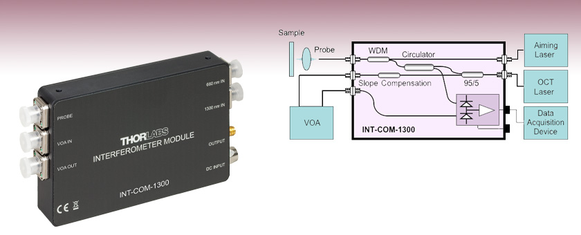
下の図1は、 INT-COM-1300内部の光回路と基本的なOCT用途向けセットアップを説明する概略図です。
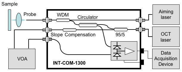
図1: INT-COM-1300の概略図
このINT-COM-1300内部のファイバ回路は、周波数掃引光源フーリエドメインOCTシステム用に設計されており、干渉計の参照アームとサンプルアームからの信号が両方ともコモンパスをたどるようになっています。両方のアームからの反射光は結合され、干渉縞を生成します。この干渉縞は差分ディテクタのチャンネルの1つで検出されます。 差分ディテクタの2つ目のチャンネルは、外部の可変光減衰器(VOA)を用いて干渉信号のDC成分をオフセットするのに利用できます。可変光減衰器は差分ディテクタの2つ目のチャンネルに入射する光量をコントロールします。
入射光は95/5の光カプラに分岐されて、95%がサーキュレータに送られます。 その後この光はWDMカプラに送られますが、WDMカプラはアライメントを容易にするために、1300 nmの入射光とガイド光を結合します。WDMカプラから出た光は、サンプル観察用プローブポートから送出されます。サンプルからの反射光は、再び回路内に戻り、WDMカプラを通って、差分ディテクタのもう1つのチャンネルで検知できるようにサーキュレータを通ります。
入射光の5%が分離され、勾配補償カプラを介して可変光減衰器(VOA)の入力ポートに入射されます。 この2番目の勾配補償カプラは、波長に依存する結合比率を補償するために使用されています。 これらの2つのカプラにより、OCTのレーザ波長にほとんど依存しないVOA入力信号が生成され、広帯域のDCオフセット補償が実現できます。このことは下の波長特性曲線で確認できます。
図2は、INT-COM-1300の1300 nm入力ポートからプローブポートまでの波長特性で、図3は入力ポートからVOA入力ポートまでの波長特性を示します。
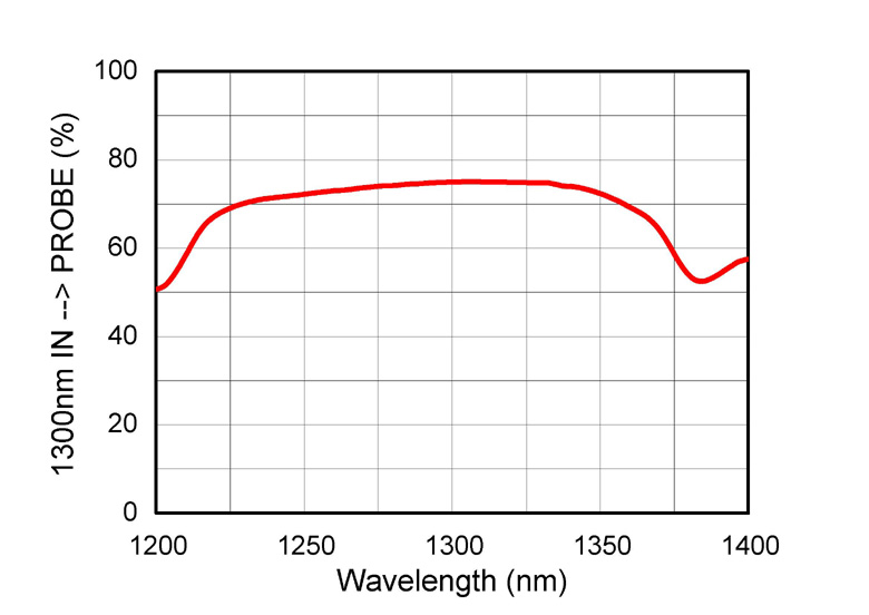 図2: 入力ポートからプローブポートまでの波長特性
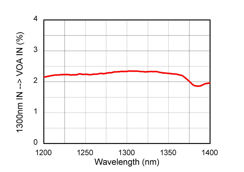 図3: 入力ポートからVOA入力ポートまでの波長特性
| Posted Comments: | |
Wilfried Hortschitz
(posted 2021-09-17 12:24:09.81) Dear sir or madam,
I do have to know what the max. temperature range for operation and storage is for the INT-COM-1300.
BR,
Wilfried dpossin
(posted 2021-09-22 09:20:34.0) Dear Wilfried,
Thank you for your feedback. The device can be stored between -40 and +70°C. All you need is to avoid condensation and therefore stay above the dewpoint. Further information can be found in my previous answer. Wilfried Hortschitz
(posted 2020-11-09 12:10:14.13) Dear Thorlabs-service team,
Can you please provide any data regarding the dependecy or a cross-sensitivity regarding the temperatur?
BR,
Wilfried dpossin
(posted 2020-11-10 03:36:53.0) Dear Wilfried,
Thank you for your feedback. Inside of the given operating temperature between 0°C and 40°C, the performance does not change significantly. However we did not tested the performance outside of the specifications but the responsivity over temperature graph of the photodiode itself tells us, that the overall change between -40°C and 70°C is just 3%. I am reaching out to you to further discuss this. Y Yang
(posted 2020-01-03 16:37:18.26) The output signal is the interference signal of reference light and sample light, right? MKiess
(posted 2020-01-03 08:11:37.0) This is a response from Michael at Thorlabs. Thank you very much for your inquiry. The INT-COM-1300 has an output SMA connector that delivers the measured OCT fringe signal. This signal is a voltage proportional to the difference between the two optical input signals of the balanced detector, and thus the difference between the photocurrents of both photodetectors.
I have contacted you directly to discuss further details. Y Yang
(posted 2019-12-31 09:40:07.987) The reflections from both arms are combined to produce the interference fringes which are detected by one channel of the integrated balanced detector. However, it can not be seen from the schematic diagram that the input of PD is the interference of two beams of light. MKiess
(posted 2020-01-02 10:59:09.0) This is a response from Michael at Thorlabs.
Thank you very much for this feedback. We will discuss whether there is a better representation for this situation. hongsoo88
(posted 2017-07-05 10:44:53.683) Our lab is trying to build swept source OCT and thinking about using OCT common-Path Interferometer(INT-COM-1300).
Can I get a data sheet or user manual for this product? I need more details about this product. swick
(posted 2017-07-05 04:06:38.0) This is a response from Sebastian at Thorlabs. Thank you for the inquiry.
Manuals and data-sheets are directly available on our website. You can click on the red button next to the part number, then a window appears where you can download the manual and other documents. nanjo
(posted 2016-08-18 03:25:11.49) Do you have any tips for optimizing the noise performance with the INT-COM-1300? Our fringe signals after FFT have a lot of noise in them, so SNR is a little low.
How should we tune the VOA? Does the optical path length of the VOA matter (from VOA input to output?
Thank you! swick
(posted 2016-08-18 06:10:44.0) This is a response from Sebastian at Thorlabs. Thank you very much for your inquiry. Basically the VOA ports are used to compensate the DC component in the interference signal. The compensation is done by adjusting the power balance at the balanced detector inputs via a VOA.
Any path length imbalance will introduce a phase shift between the two optical signals detected which will decrease noise reduction performance.
While the inner path lengths are nearly identical the external path length has to be matched. As a rule of thumb, the PROBE-to-sample optical path length shall be half of the optical path length between VOA IN and VOA OUT. Please see also page 19 in the manual.
Unfortunately, the email address which you have left on this feedback is not working. We would like to discuss your questions about noise and your setup in detail. Please use europe@thorlabs.com for contacting us directly. avle
(posted 2016-06-20 02:56:59.263) Will this work with a 50khz sweep rate laser? shallwig
(posted 2016-06-23 05:38:07.0) This is a response from Stefan at Thorlabs. Thank you very much for your inquiry. The frequency of the detected fringe signals is proportional to laser sweep rate, total wavelength sweep range, and the probing interferometer delay. The peak electronic fringe frequency of a sine wave drive laser is: f_peak=-1.57*k *(deltaLambda)*L/(Lambda)^2
The board of the INT-COM-1300 can resolve up to 15 MHz. Depending on the parameters of your laser and setup a laser with a sweep rate of 50kHz can be used. I have contacted you directly to discuss your application in more detail. anthony
(posted 2016-04-09 22:50:03.79) Can you quote for the common path interferometer with 400mhz bandwidth PN INT-COM-1300?
Thank you shallwig
(posted 2016-04-11 03:59:05.0) This is a response from Stefan at Thorlabs. Thank you very much for your inquiry. We will contact you directly to provide you with a quote for this special with 400 MHz bandwidth. jlow
(posted 2012-08-10 09:19:00.0) Response from Jeremy at Thorlabs: You do not need a polarization controller for this because the interferometer does not require polarized light. ggjmlee
(posted 2012-08-10 14:26:33.0) Do I need polraization cotroller to get a signal throught this interferometer? jvigroux
(posted 2011-07-15 11:19:00.0) A response form Julien at Thorlabs: we shoud be able to offer a custom ineterferometer having a bandwidth of 100MHz with a transimpedance gain of 100kV/A. I will contact you directly to see if those values would meet your requirements. avle
(posted 2011-07-14 14:11:25.0) Hi there,
Is it possible to increase the bandwidth of the TIA from 15mhz to 100mhz by adjusting internal values of the TIA circuit?
Thanks! |