 Products Home
Programmable Benchtop Power Supply
- Four Independent Channels with Ultra-Low Output Ripple and Noise
- Up to 60 V or 10 A Output Using Internal Series or Parallel Connections
- Programmable Output Values or On/Off States
BPS330
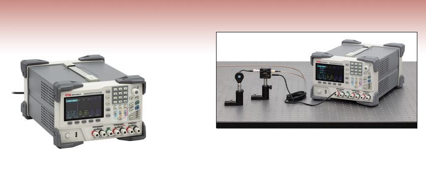
Programmable Benchtop Power Supply
Application Idea
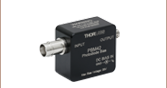
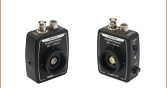
A BPS330 Power Supply and PBM42 Bias-T are used with an SM1PD1B Photodiode.


Please Wait
| Table 1.1 Key Specificationsa | ||||||
|---|---|---|---|---|---|---|
| Channel | 1 or 2 | 1 and 2 (Series) | 1 and 2 (Parallel) | 3 | 4 | |
| Voltage Output Ratingb | 0 - 30 V | 0 - 60 V | 0 - 30 V | 0 - 6 V | 5 Vc | |
| Current Output Rating | 0 - 5 A | 0 - 5 A | 0 - 10 A | 0 - 3 A | 2 Ac | |
| Output Power | 348 W Total | |||||
| Constant Voltage Mode (All Channels) | ||||||
| Power Supply Regulationd | ≤0.01% + 2 mV | |||||
| Ripple and Noise | <350 µVrms and <2 mVpp (5 Hz - 1 MHz) | |||||
| Constant Current Mode (All Channels) | ||||||
| Power Supply Regulationd | ≤0.01% + 250 µA | |||||
| Ripple Current | <2 mArms | |||||
| Programmed Voltage Speed (1% of Total Variation Range) | ||||||
| Full Load Rise Time | <50 ms | - | - | <15 ms | - | |
| Full Load Fall Time | <45 ms | - | - | <22 ms | - | |
| No Load Rise Time | < 30 ms | - | - | <13 ms | - | |
| No Load Fall Time | <400 ms | - | - | <100 ms | - | |
| Size | ||||||
| Dimensions (W x D x H) | 355 mm x 240 mm x 168 mm (14.0" x 9.4" x 6.6") | |||||
Features
- Four Independent Output Channels
- Constant Voltage or Constant Current Modes Available for Channels 1 - 3
- Channels 1 and 2 can be Internally Combined in Series or Parallel
- Ultra-low Output Ripple and Noise
- Programmable Output with Waveforms that can be Displayed on the LCD Screen:
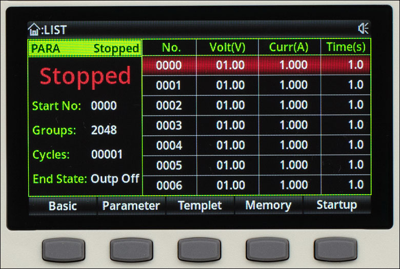
- List Mode: Set Output Voltage or Current Using Templates or Manual Entry
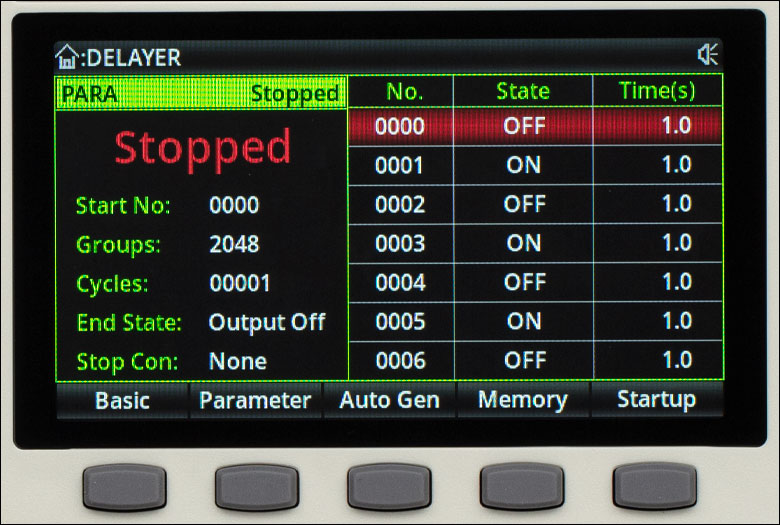
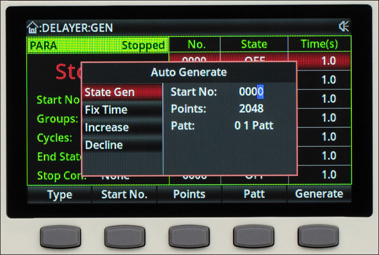
- Delayer Mode: Set Output On or Off States Using Templates or Manual Entry
- Input or Output Triggering Available
The BPS300 Programmable Benchtop Power Supply has four independent output channels with ultra-low output noise and ripple, providing a versatile source of power for instruments. Channels 1 and 2 provide up to 30 V with up to 5 A of output, and they can be combined internally to provide up to 60 V in series or 10 A in parallel by pressing the SER or PARA buttons on the front panel; see Figure 3.1 in the Front & Back Panels tab for their locations. Channel 3 provides an output of up to 6 V and up to 3 A, while Channel 4 provides a constant output voltage of 5 V with a current of up to 2 A in the USB output on the Front Panel.
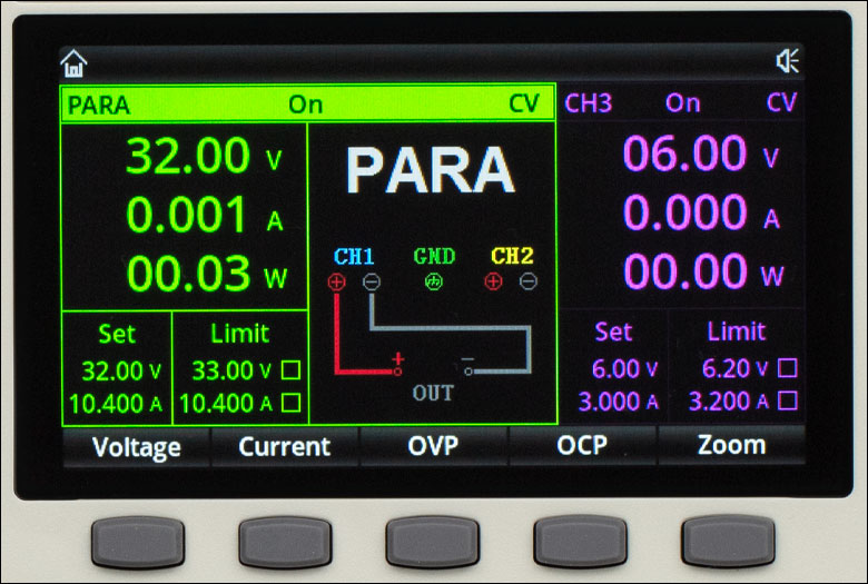
Channels 1 - 3 and Channels 1 and 2 when combined in series or parallel mode can be set using constant voltage or constant current mode, and limiting values for the output current and voltage can be set to protect the connected circuit. The internal memory of the power supply can save up to five sets of values for the output voltage, current, and limits for Channels 1 - 3. In the default view, the front panel's color 4.3" LCD screen's default display shows the output voltage, current, and power of Channels 1 - 3, in addition to the voltage and current set and limiting values; see Figure 1.2. When Channels 1 and 2 are set in Series or Parallel mode using the SER or PARA button on the front panel, a connection diagram on the LCD screen shows the required connections, and the combined values of the parameters are displayed; see Figure 1.3 here and 4.1 in the LCD Screen tab for images of the screen in these modes.
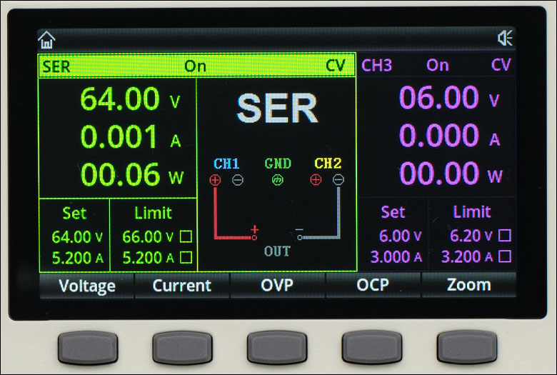
Figure 1.3 BPS330 Power Supply Series Mode Screen: A connection diagram is shown and the output values and settings for the series connection are displayed on the left side of the screen.
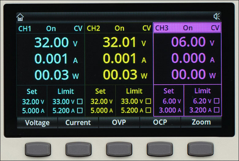
Figure 1.2 BPS330 Power Supply Default Mode Screen: The output values and settings for Channels 1 - 3 are displayed. CV indicates the instrument is in constant voltage mode. When a channel is operated in constant current mode, a CC will be shown instead. The checkboxes next to each limit indicate the limit is active when checked.
Programmable Modes
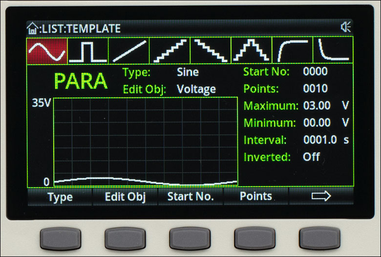
The BPS330 power supply has List and Delayer modes to generate a time-varying output with up to 2048 different values, which can be cycled up to 99 999 times. List mode outputs a specific set of voltage or current values at set times and Delayer mode outputs specific on and off states at set times. The list and delayer functions can be set manually by entering the data in the user interface or using the provided templates. Sine, Pulse, Ramp, Stair Up, Stair Down, Stair Up Down, Exponential Rise, and Exponential Fall templates are available for Lists and State Generation, Fixed Time, Increase, and Decline templates are available for the Delayer. Please see Figures 4.2, 4.3, 4.5, and 4.6 in the LCD Screen tab for images of the LCD screen for these modes and the manual for the BPS330 power supply for detailed descriptions of each of the templates.
The internal memory of the instrument can store up to 10 groups of values each for the list and delayer modes, in addition to 10 instrument state files that include the voltage and current, limits, and settings for triggers, monitors, and computer connection settings. These files can also be stored externally, limited by the size of the external storage. Note that, for an individual channel, the list and delayer functions are exclusive; the activation of one causes the other to be disabled.
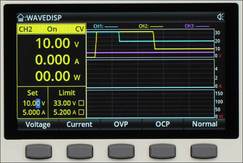
When using time-varying outputs with List and Delayer modes, the Waveform Display screen can be selected to display the output voltage, current, and power over time of each channel. There is an input I/O port on the back panel with four channels that can be used as a trigger input or output for different trigger conditions. Please see Figures 4.4, 4.7, and 4.8 in the LCD Screen tab for images of these screens.
| BPS330 Power Supply Specifications | ||||||
|---|---|---|---|---|---|---|
| Channel | 1 or 2 | 1 and 2 (Series) | 1 and 2 (Parallel) | 3 | 4 | |
| Voltage Output Ratinga | 0 - 30 V | 0 - 60 V | 0 - 30 V | 0 - 6 V | 5 ± 0.25 Vb | |
| Current Output Rating | 0 - 5 A | 0 - 5 A | 0 - 10 A | 0 - 3 A | 2 Ab | |
| Power Output Rating | 348 W Total | |||||
| Constant Voltage Mode (All Channels) | ||||||
| Line Regulationc | ≤0.01% + 2 mV | |||||
| Load Regulationc | ≤0.01% + 2 mV | |||||
| Ripple and Noise | <350 µVrms and <2 mVpp (5 Hz - 1 MHz) | |||||
| Response Time | ≤50 µs (50% Load Variation, Minimum Load 0.5 A) | |||||
| Command Processing Time | <100 ms | |||||
| Constant Current Mode (All Channels) | ||||||
| Line Regulationc | ≤0.01% + 250 µA | |||||
| Load Regulationc | ≤0.01% + 250 µA | |||||
| Ripple Current | <2 mArms | |||||
| Tracking Mode | ||||||
| Line Regulationc | - | ≤0.01% + 3 mV | ≤0.01% + 2 mV | - | - | |
| Load Regulationc | - | ≤300 mV | ≤0.01% + 2 mV | - | - | |
| Tracking Errorc | ≤0.5% + 30 mV (0 - 9.99 V, No Load), ≤0.5% + 10 mV (10 - 30 V, No Load), Connected Load ≤300 mV, Access Load ≤300mA |
|||||
| Measurement | ||||||
| Display Voltage and Current Full Scale | 4-Digit Display, 4.3" LCD | |||||
| Programming Resolution | Voltage: 10 mV, Current: 1 mA | |||||
| Read Back Resolution | Voltage: 10 mV, Current: 1 mA | |||||
| Programming Accuracy (25 ± 5 °C)d | Voltage: ±(0.3% + 20 mV), Current: ±(0.2% + 5 mA) | |||||
| Read Back Accuracy (25 ± 5 °C)d | Voltage: ±(0.1% + 20 mV), Current: ±(0.15% + 5 mA) | |||||
| Programmed Voltage Speed (1% of Total Variation Range) | ||||||
| Full Load Rise Time | <50 ms | - | - | <15 ms | - | |
| Full Load Fall Time | <45 ms | - | - | <22 ms | - | |
| No Load Rise Time | <30 ms | - | - | <13 ms | - | |
| No Load Fall Time | <400 ms | - | - | <100 ms | - | |
| Temperature Coefficient (per °C, Output % + Offset) | ||||||
| Voltage | 0.01% + 5 mV | - | - | 0.01% + 2 mV | - | |
| Current | 0.01% + 2 mA | - | - | 0.01% + 2 mA | - | |
| Input Power | ||||||
| Voltage | AC: 100 V, 120 V, 220 V, or 230 V ± 10% | |||||
| Frequency | 50 Hz or 60 Hz | |||||
| Power | 600 W Maximum | |||||
| Fuse | AC220V: T4AL250V, AC110V: T8AL250V | |||||
| Environment | ||||||
| Operating Temperature | 0 - 40 °C | |||||
| Operating Humidity | 20 - 80% (Non-Condensing) | |||||
| Storage Temperature | -10 - 60 °C | |||||
| Altitude | ≤2000 m | |||||
| Pollution Degree | 2 | |||||
| Size and Weight | ||||||
| Dimensions (W x D x H) | 355 mm x 240 mm x 168 mm (14.0" x 9.4" x 6.6") | |||||
| Weight | 10.2 kg | |||||
BPS330 Power Supply Front and Back Panels

Click to Enlarge
Figure 3.2 Back Panel
Click to Enlarge
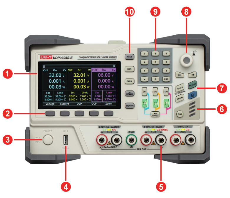
Figure 3.1 Front Panel
| Back Panel | |
|---|---|
| Callout | Description |
| 1 | Cooling Fan (Do Not Block) |
| 2 | Fuse Tray |
| 3 | AC Input Socket |
| 4 | AC Input Source Selection |
| 5 | RS-232 Input Connector for Remote Control |
| 6 | Digital I/O Ports With Connector Installed |
| 7 | USB Type-B Port for Remote Control |
| 8 | Ethernet Connector for Remote Control |
| 9 | USB Type-A Port for Remote Control |
| Front Panel | |
|---|---|
| Callout | Description |
| 1 | 4.3" LCD Display |
| 2 | Operation Menu Keys |
| 3 | Power On/Off Key |
| 4 | Channel 4 USB Output: 5 V, 2 A |
| 5 | Output Banana Plug (4 mm) Binding Post Connectors and Indicators |
| 6 | Channel 3 Quick Selection Key |
| 7 | Keyboard Lock, Preset, Utility, and Home Key |
| 8 | Rotary Knob: Select or Edit a Parameter, Press to Confirm |
| 9 | Digital Numerical Keyboard |
| 10 | Wave, Series (SER), Parallel (PARA), List/Delayer, and Storage Keys |
BPS330 Power Supply LCD Screen Examples
Click to Enlarge
Figure 4.3 Delayer Manual Entry Screen: A list of set output ON or OFF states and times can be manually entered.
Click to Enlarge
Figure 4.2 List Manual Entry Screen: A list of set output voltage or current values and times can be manually entered.
Click to Enlarge
Figure 4.1 Parallel Screen: A connection diagram is shown and the output values and settings for the parallel connection are displayed.
Click to Enlarge
Figure 4.6 Delayer Template Screen: State Generation, Fixed Time, Increase, and Decline templates are available.
Click to Enlarge
Figure 4.5 List Template Screen: Sine, Pulse, Ramp, Stair Up, Stair Down, Stair Up Down, Exponential Rise, and Exponential Fall templates are available.
Click to Enlarge
Figure 4.4 Waveform Screen: The output voltage, current, and power waveforms of channels 1 - 3 can be displayed. Note that the power supply was not connected to an output for this measurement, so the current and power shown are zero in this image.
Click to Enlarge
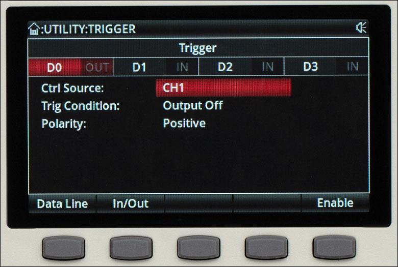
Figure 4.8 Trigger Out Screen: An output trigger can be generated based on a programmable trigger condition.

Click to Enlarge
Figure 4.7 Trigger In Screen: A trigger input from an external source can be set up to trigger the power supply.

Click to Enlarge
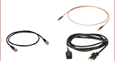
The BPS330 Programmable Benchtop Power Supply is shipped with an appropriate power cable, USB cable, and paperwork. The input connector for the Digital I/O port is shipped in the box separately from the power supply and should be installed in the back upon receipt. See Figure 3.2 in the Front & Back Panels tab for its location.
The BPS330 Programmable Benchtop Power Supply contains the following components:
- BPS330 Power Supply
- Power Cable According to Local Power Supply, 1.8 m
- USB 2.0 Type-A to Type-B Cable, 1.5 m
- Digital I/O Connector
- Certificate of Calibration
- Multi-Language Safety Precautions
- User Manual
- Packing List
Software for the BPS330 Programmable Benchtop Power Supply
Version 2.00
The BPS330 Programmable Benchtop Power Supply Software package is a GUI for controlling the power supply.
| Posted Comments: | |
| No Comments Posted |