 Products Home / 光ファイバーケーブル&光ファイバーパッチケーブル / 偏波保持(PM)シングルモードパッチケーブル / Polarization-Maintaining FC/APC Fiber Optic Patch Cables with Heating Wires
Polarization-Maintaining FC/APC Fiber Optic Patch Cables with Heating Wires
- PM Fiber Heater Driver and Compatible PM Patch Cables with Nichrome Heating Wire
- Enables Ultra-High-Precision Alignment of Input Polarization to the PM Axis
- Improves the Ouput Polarization Stability After PM Fiber
- Available for Wavelength Ranges Between 400 and 1625 nm
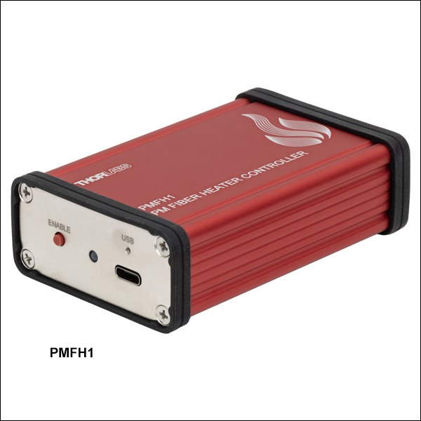
PMFH1
PM Fiber Heater Driver
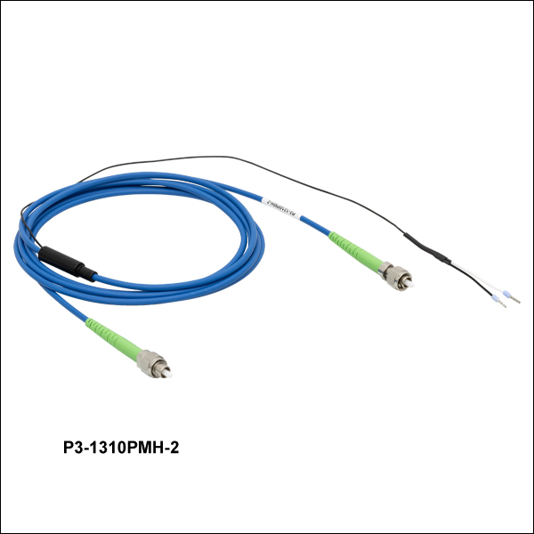
P3-630PMH-2
620 - 850 nm PM Patch Cable with Heating Wires
P3-1060PMH-2
970 - 1550 nm PM Patch Cable with Heating Wires
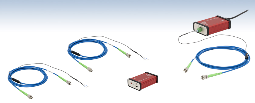
Application Idea
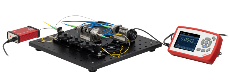
A PMFH1 PM Fiber Heater Driver heats a P2-1550PMH-2 PM Patch Cable with Heating Wire for improved output polarization stability.


Please Wait
Applications
- Quantum Optics
- Quantum Information Processing
- Precision Physics
- Laser Spectroscopy and Interferometry
- Atomic Clocks
- Fiber-Based Data Transmission
- Fiber-Based Quantum Networks
- Fiber-Based Quantum or Classical Sensors
- Generation of Optical Vortex Beams
| PM Patch Cables with Heating Wire Selection Guide | |
|---|---|
| Item # | Operating Wavelength Range |
| P3-405PMH-2 | 400 to 680 nm |
| P3-488PMH-2 | 460 to 700 nm |
| P3-630PMH-2 | 620 to 850 nm |
| P3-780PMH-2 | 770 to 1100 nm |
| P3-1060PMH-2 | 970 to 1550 nm |
| P3-1310PMH-2 | 1270 to 1625 nm |
| P3-1550PMH-2 | 1440 to 1625 nm |
Click to Enlarge
Figure 1.1 Optical setup for using the PMFH1 PM Fiber Heater Driver with a P3-630PMH-2 PM Patch Cable with Nichrome Heating Wire for alignment of the input polarization to the PM fiber's slow axis. For details on the recommended alignment process, see the Operation tab.
Features
- Polarization-Maintaining FC/APC Patch Cables with Nichrome Heating Wire
- Narrow Key (2.0 mm) Aligned to Slow Axis
- Typical Return Loss of 60 dB
- Ceramic 8° Angled Ferrule on APC Connector
- Ø3 mm Protective Outer Jacket
- PMFH1 Driver Heats Compatible PM Patch Cables at 0.1 Hz from 0 to 10 V with a 50% Duty Cycle to Modulate the Birefringence
- Oscillating Temperature Allows Ultra-High-Precision Alignment of the Input Polarization with the Fiber's PM Axis
- Align Once for Stable Long-Term Polarization
- Custom PM Patch Cables with Heating Wire Available
Our P3-xxxPMH-2 Polarization-Maintaining (PM) Patch Cables with Nichrome Heating Wire are designed to allow ultra-high-precision adjustment of an input laser's polarization axis to the PM fiber's slow (or fast) axis. The PMFH1 PM Fiber Heater Driver applies a 0.1 Hz square-wave voltage from 0 to 10 V with a 50% duty cycle to the heating wires of the P3-xxxPMH-2 PM patch cables to oscillate the temperature of the fiber and thus the birefringence.
For a PM fiber to maintain polarization, the input light must be aligned into the PM axis of the fiber, which is challenging to achieve with the sub-degree precision necessary for many applications in optics, where the stability of the polarization of the output light from a PM fiber must be optimal to achieve the desired results. Additionally, when aligning light into a PM fiber, the environmental conditions during alignment can cause a suboptimal alignment between the PM axis of the fiber and the incoming light's polarization axis. Even when a high extinction ratio is achieved at the output, the output polarization can shift over time with further environmental fluctuations, due to misalignment with the fiber's PM axis.
To achieve the highest stability output polarization from a PM fiber, a useful trick for the input polarization alignment is to apply oscillating heat to the fiber to perturb the birefringence and cause an oscillation of the phase between the light coupled into the PM fiber's fast and slow axes. The measured oscillations on the polarization output should then be minimized until the light is precisely aligned to the PM axis of the fiber, leading to a long-term stable output polarization from the fiber due to the increased alignment accuracy. Although sometimes this is accomplished using a heated breadboard or other external heating methods, these methods also change the temperature of the mounts and optical components, which can lead to other problems. With a P3-xxxPMH-2 PM patch cable with heating wire and the PMFH1 heater driver, only the fiber is heated, removing those issues. Please see Figure 1.1 for a recommended setup for aligning the polarization of an S1FC635 Laser to a P3-630PMH-2 patch cable with heating wire using Thorlabs’ FiberBenches.
Once the input polarization is precisely aligned to the fiber's polarization using the PMFH1 heater driver to oscillate the temperature, the heater driver can be removed, and the output polarization is stable. The heat can be reapplied to realign the PM fiber if it becomes misaligned, but it is not needed on a day-to-day basis, as the precise alignment to the PM axis of the fiber means the system is much less sensitive to the environment. Only one heater driver is needed, as it can be used to align multiple P3-xxxPMH-2 patch cables, one at a time. Please see the Operation tab for details on how to align polarized light into a compatible P3-xxxPMH-2 patch cable using the PMFH1 heater driver.
If you cannot find the appropriate stock PM patch cable with heating wire your application requires, custom patch cables are available. Our PM patch cables with heating wire can be customized with different lengths, connectors, and fibers. Please contact Tech Support for more information.
| Table 2.1 Patch Cable Specifications | |||||||
|---|---|---|---|---|---|---|---|
| Item # | P3-405PMH-2 | P3-488PMH-2 | P3-630PMH-2 | P3-780PMH-2 | P3-1060PMH-2 | P3-1310PMH-2 | P3-1550PMH-2 |
| Alignment Wavelength | 405 nm | 488 nm | 630 nm | 780 nm | 1064 nm | 1310 nm | 1550 nm |
| Fiber Item # | PM-S405-XP | PM460-HP | PM630-HP | PM780-HP | PM980-XP | PM1300-XP | PM1550-XP |
| Operating Wavelength Range | 400 to 680 nm | 460 to 700 nm | 620 to 850 nm | 770 to 1100 nm | 970 to 1550 nm | 1270 to 1625 nm | 1440 to 1625 nm |
| Mode Field Diametera | 3.3 ± 0.5 µm @ 405 nm 4.6 ± 0.5 µm @ 630 nm |
3.3 ± 0.5 µm @ 515 nm | 4.5 ± 0.5 µm @ 630 nm | 5.3 ± 1.0 µm @ 850 nm | 6.6 ± 0.5 µm @ 980 nm | 9.3 ± 0.5 µm @ 1300 nm | 10.1 ± 0.4 µm @ 1550 nm |
| Cladding Diameter | 125 ± 2 µm | ||||||
| Coating Diameter | 245 ± 15 µm | ||||||
| Cutoff Wavelength | 380 ± 20 nm | 410 ± 40 nm | 570 ± 50 nm | 710 ± 60 nm | 920 ± 50 nm | 1210 ± 60 nm | 1380 ± 60 nm |
| NA | 0.12 | 0.125 | |||||
| Insertion Loss | 1.50 dB (Max) 1.20 dB (Typ.) |
1.50 dB (Max) 1.20 dB (Typ.) |
1.20 dB (Max) 1.00 dB (Typ.) |
1.00 dB (Max) 0.70 dB (Typ.) |
0.70 dB (Max) 0.50 dB (Typ.) |
0.50 dB (Max) 0.30 dB (Typ.) |
0.50 dB (Max) 0.30 dB (Typ.) |
| Extinction Ratio | 15 dB (Max) 17 dB (Typ.) |
18 dB (Max) 20 dB (Typ.) |
20 dB (Max) 22 dB (Typ.) |
20 dB (Max) 22 dB (Typ.) |
22 dB (Max) 24 dB (Typ.) |
23 dB (Max) 25 dB (Typ.) |
23 dB (Max) 25 dB (Typ.) |
| Optical Return Loss (Typical) | 60 dB | ||||||
| Connector | |||||||
| Connector Type | FC/APC | ||||||
| Key Width | Narrow (2.0 mm) | ||||||
| Key Alignment | Slow Axis | ||||||
| General | |||||||
| Operating Temperature | 0 to 70 °C | ||||||
| Storage Temperature | -45 to 85 °C | ||||||
| Recommended Voltage | 10 V | ||||||
| Table 2.2 Heater Driver Specifications | ||||||
|---|---|---|---|---|---|---|
| Item # | PMFH1 | |||||
| Output Signala | 0 - 10 V, 100 mA, 0.1 Hz, 50% Duty Cycle | |||||
| Output Enable | Tactile Switch | |||||
| Indicatorb | LED | |||||
| Power Connector | USB Type-C | |||||
| Maximum Current | 400 mA | |||||
| Output Connector | Removable Terminal Block (Included) | |||||
| Operating Temperature | 0 to 40 °C (Non-Condensing) | |||||
| Storage Temperature | -40 to 85 °C | |||||
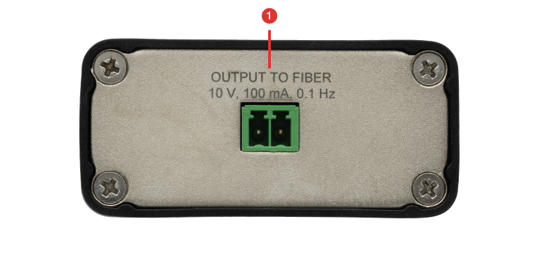
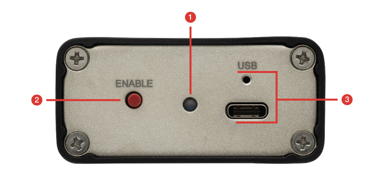
PMFH1 Heater Driver Front and Back Panels
Click to Enlarge
Figure 3.2 PMFH1 Heater Driver Back Panel
Click to Enlarge
Figure 3.1 PMFH1 Heater Driver Front Panel
| Back Panel | |
|---|---|
| Callout | Description |
| 1 | Heater Driver Output Connector (Terminal Block Included) |
| Front Panel | |
|---|---|
| Callout | Description |
| 1 | LED Status Indicator Blue LED: System is powered in standby. Green LED: Output Enabled Red LED: Error caused by an overcurrent condition. Amber LED: Error caused by an undercurrent condition. |
| 2 | Enable Heater Driver Output |
| 3 | Lockable USB Type-C Connector for Input Power with Threading for Locking Screw (M2 x 0.4 Tapped Hole) |
Alignment of P3-xxxPMH-2 PM Patch Cables with Nichrome Heating Wire Using the PMFH1 PM Fiber Heater Driver
For some helpful background information on PM Fibers, please read our PM Fiber Insight.
Alignment Setup
Figure 4.1 shows a schematic for aligning light into a PM fiber patch cable. The input laser source goes through a single mode (SM) fiber within a three-paddle polarization controller, followed by a polarizer, which polarizes the laser light or cleans up the polarization. The polarizer's axis should be along the same direction as the PM fiber's slow axis in most cases, which is aligned to the connector key for the fibers sold on this page.
Click to Enlarge
Figure 4.1 Recommended Schematic for Aligning a PM Patch Cable with Nichrome Heating Wire (See Figure 1.1 in the Overview Tab for a Sample Parts List for P3-630PMH-2 Patch Cable Alignment)
The polarizer is followed by a half-wave plate (HWP), which can be used to rotate the linear polarization going into the fiber, with an optional quarter-wave plate (QWP) after the HWP for perfecting the linear polarization. After the PM fiber, an analyzing polarizer followed by a photodetector is used to analyze how well the laser's polarization is aligned to the PM axis of the fiber. Additionally, adding a QWP and HWP before the analyzer, once the PM fiber is aligned, allows the cleanest possible linear polarization output for use in a polarization-sensitive application.
Note that improved output polarization results may be achievable by putting the HWP before the polarizer on the input FiberBench, but the alignment process is more complex in that case.
Extinction Ratio
The extinction ratio (ER) of the light after the fiber is given by:

The analyzing polarizer should be perpendicular to the PM axis of the fiber for the best alignment signal-to-noise ratio, in a crossed-polarizer configuration. The PMFH1 heater driver enables precise tuning of the HWP alignment before the PM fiber using the oscillations in the signal produced by the applied heat. A QWP is then added to clean up any elliptical polarization to achieve ultra-high-precision alignment into the fiber's PM axis. Without using the PM fiber heater driver, the ER after alignment into a P3-1550PMH-2 PM patch cable varies between about 25 and 30 dB when the heat is turned on after alignment, as shown in Figure 4.2. By using the PMFH1 heater driver to align the polarization into the fiber, the ER varies between about 44.75 and 47.25 dB, as seen in Figure 4.3. The average ER was increased by about 19.4 dB with the optics used in this measurement, after carefully following this alignment procedure. The misalignment angles are shown on the right side of the graphs; they were calculated with Malus' Law. Note that the average misalignment angle went down by almost a factor of 10 after using the PMFH1 heater driver for alignment. In this example, the measurement approached the noise floor of the detector; an improved ER may be possible with a higher-power laser source.
Click to Enlarge
Figure 4.3 ER and Misalignment Angle After Alignment of P3-1550PMH-2 Using the PMFH1 Heater Driver (Heat On for Alignment and Measurement, Note the Scaling on the Y-Axis is Different in Figures 4.2 and 4.3)
Click to Enlarge
Figure 4.2 ER and Misalignment Angle After Alignment of P3-1550PMH-2 Without Using PMFH1 Heater Driver (Heat On for Measurement but not Alignment, Note the Scaling on the Y-Axis is Different in Figures 4.2 and 4.3)

Click to Enlarge
Figure 4.4 Poincaré Sphere After PM Fiber With Oscillating Heat
Polarimeter Measurements
Although not necessary for achieving the ultra-high-precision PM fiber alignment results shown in Figure 4.3, a polarimeter, such as our PAX1000 Series Polarimeters, can be used to evaluate the ER during alignment, if available, or to visualize the state of polarization after alignment. For background information on using the Poincaré sphere to represent a state of polarization, see our Polarization Insights or watch our webinar on Characterizing Beam Polarization.
The typical polarization output of a PM fiber results in an elliptical polarization, which shows up on the Poincaré sphere as a point on the sphere that is off of the equator, where polarization states with perfect linear polarization lie. Oscillating the fiber temperature will lead to the polarization tracing out a circle around this point on the Poincaré sphere, as shown in Figure 4.4. The ER can be calculated from the angles on the sphere.
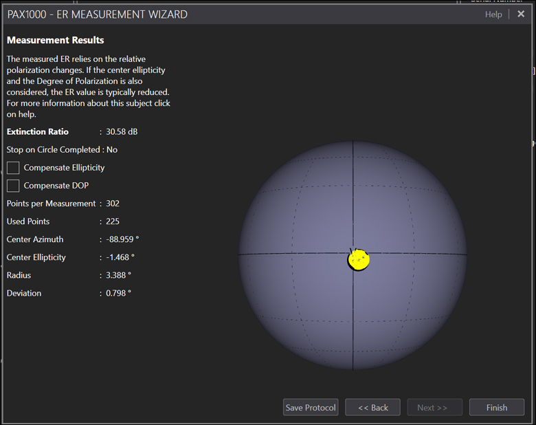
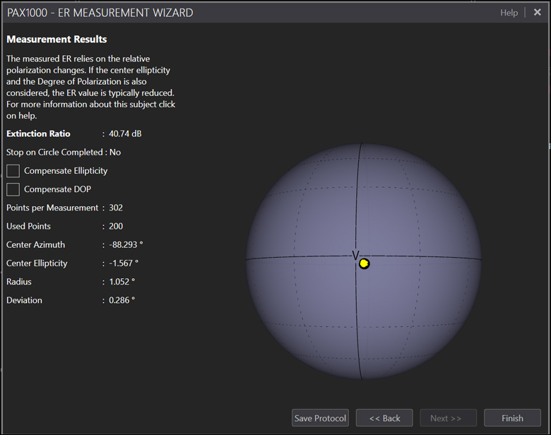
The polarimeter measurement results after aligning a P3-780PMH-2 patch cable without using the PMFH1 heater driver are shown in Figure 4.5. The heat was turned on during the measurement, and the yellow circle indicates the polarization drift due to the changing temperature and the misalignment between the PM axis and the input polarization. The polarimeter measurement results after aligning the fiber using the PMFH1 heater driver, as described above, are much more stable to the temperature fluctuations when the heat is on. The yellow circle of the polarization over time, as shown in Figure 4.6, now appears as a point because the polarization after alignment using the PMFH1 heater driver barely moves on the Poincaré sphere
Click to Enlarge
Figure 4.5 Poincaré Sphere After Alignment of a P3-780PMH-2 Patch Cable With Nichrome Heating Wire Without Using the PMFH1 Heater Driver (Heat On)
Click to Enlarge
Figure 4.6 Poincaré Sphere After Alignment of a P3-780PMH-2 Patch Cable With Nichrome Heating Wire Using the PMFH1 Heater Driver (Heat On)
| Posted Comments: | |
| No Comments Posted |

 ズーム
ズーム- FC/APC PM Patch Cables with Nichrome Heating Wire
- Designed for Use with the PMFH1 PM Fiber Heater Driver
- Allows Ultra-High-Precision Alignment of an Input Laser's Polarization to the PM Axis of the Fiber
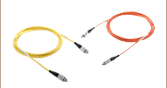
Thorlabs' P3-xxxPMH-2 Patch Cables with Nichrome Heating Wire cover input wavelengths from 400 to 1625 nm, with narrow key (2.0 mm) FC/APC connectors that are aligned to the slow axis of the PM fiber inside the Ø3 mm jacket. The heating wires can be connected to the PMFH1 heater driver using the removable terminal block, which allows oscillating heat to be applied to the PM fiber, causing the birefringence of the fiber to fluctuate. The oscillations can be used to align the polarization into the PM fiber with almost a 10x lower misalignment angle, as shown in Figures 4.2 and 4.3 in the Operation tab, which includes an alignment schematic and directions. For a sample parts list for aligning a P3-630PMH-2 patch cable, see Figure 1.1 in the Overview tab.
One heater driver can be used with multiple patch cables, as it is only needed for the initial alignment of the fiber, or when the polarization becomes misaligned. The polarization of the output from the P3-xxxPMH-2 patch cable after alignment with the PMFH1 heater driver is much more stable than without using the driver. Once the alignment is complete, the heater driver can be removed and used for aligning another patch cable, if needed.
Note that a function generator can be connected to the heating wire of the P3-xxxPMH-2 patch cables if one is available. We recommend driving the wires using the output signal specifications in Table 2.2 in the Specs tab. Please see the PMFH1 heater driver manual, which includes a detailed alignment protocol for these PM patch cables that should be followed regardless of which type of driver is used.
| Figure G2.1 PM Patch Cables with Heating Wire Key Specificationsa | ||||||
|---|---|---|---|---|---|---|
| Item # | Alignment Wavelength | Fiber Item # | Wavelength Range | MFDb | Cutoff Wavelength | NAc |
| P3-405PMH-2 | 405 nm | PM-S405-XP | 400 to 680 nm | 3.3 ± 0.5 µm @ 405 nm 4.6 ± 0.5 µm @ 630 nm |
380 ± 20 nm | 0.12 |
| P3-488PMH-2 | 488 nm | PM460-HP | 460 to 700 nm | 3.3 ± 0.5 µm @ 515 nm | 410 ± 40 nm | |
| P3-630PMH-2 | 630 nm | PM630-HP | 620 to 850 nm | 4.5 ± 0.5 µm @ 630 nm | 570 ± 50 nm | |
| P3-780PMH-2 | 780 nm | PM780-HP | 770 to 1100 nm | 5.3 ± 1.0 µm @ 850 nm | 710 ± 60 nm | |
| P3-1060PMH-2 | 1064 nm | PM980-XP | 970 to 1550 nm | 6.6 ± 0.5 µm @ 980 nm | 920 ± 50 nm | |
| P3-1310PMH-2 | 1310 nm | PM1300-XP | 1270 to 1625 nm | 9.3 ± 0.5 µm @ 1300 nm | 1210 ± 60 nm | |
| P3-1550PMH-2 | 1550 nm | PM1550-XP | 1440 to 1625 nm | 10.1 ± 0.4 µm @ 1550 nm | 1380 ± 60 nm | 0.125 |

Figure G2.2 The FC/APC Connector Key is Aligned to the PM Fiber Slow Axis

 ズーム
ズーム- Outputs a Drive Signal to Apply Oscillating Heating to PM Patch Cables with Heating Wire
- Square-Wave Signal From 0 to 10 V at 100 mA and 0.1 Hz, with a 50% Duty Cycle
- Compatible with P3-xxxPMH-2 Patch Cables with Nichrome Heating Wire, Sold Above
- USB Cable and Power Supply Sold Separately Below
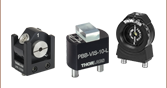
The PMFH1 PM Fiber Heater Driver is designed for use with our specially designed PM Patch Cables with Nichrome Heating Wire, which are sold above for a variety of operating wavelength ranges. The heater driver can be connected to the wires on a compatible patch cable using the removable terminal block that accepts the ferrules on the ends of the wires installed within our P3-xxxPMH-2 patch cables. Note that a small flathead screwdriver, such as one from our PSS7 screwdriver set, is required to install the ferrules in the terminal block. The heater driver applies a 50% duty cycle, 0.1 Hz oscillating square wave from 0 to 10 V with 100 mA of current to the heating wires when the power is enabled. Once connected, it is switched on or off with the simple tactile enable switch on the front panel (see the Front & Back Panels tab for details).
Note that the PMFH1 heater driver is powered through the USB Type-C connector on the front panel using a compatible USB power supply and cable. We recommend using our DS5 power supply and our CABCUL72 USB 3.0 Type-A to Type-C Cable with Locking Screw, sold separately below. Note that, in the event of a short circuit, some USB power supplies may cause the PMFH1 heater driver’s internal PD circuit to disable the voltage, causing the PMFH1 heater driver to shut down. Removing the short and cycling the power will reset the system. Using the recommended Thorlabs DS5 power supply, the short circuit error detection will operate as normal, shutting down the output and turning the status LED red.
パッチケーブル | PMパッチケーブル |