 Products Home
O-Band and C-Band Tunable Bandpass Filters
- Digital Tunable Bandpass Filters for 1265 - 1355 nm or 1527 - 1567 nm
- ≥0.2 nm Passband Widths at -3 dB and ≤0.8 nm Passband Widths at -20 dB
- 50 GHz Dense Wavelength Division Multiplexing (DWDM) ITU Grid for C-Band
- >25 dB Non-Adjacent Isolation
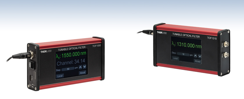
TOF1550
Tunable Bandpass Filter,
1527 - 1567 nm
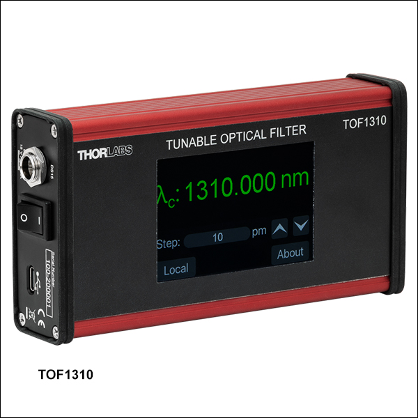
TOF1310
Tunable Bandpass Filter,
1265 - 1355 nm


Please Wait
| Key Specifications | ||
|---|---|---|
| Item # | TOF1310 | TOF1550 |
| Wavelength Tuning Range | 1265 - 1355 nm | 1527 - 1567 nm |
| Passband Width @ -1 dBa | ≥0.12 nm (21.0 GHz) | ≥0.12 nm (15.0 GHz) |
| Passband Width @ -3 dBa | ≥0.2 nm (34.9 GHz) | ≥0.21 nm (26.2 GHz) |
| Passband Width @ -20 dBa | ≤0.8 nm (139.7 GHz) | ≤0.77 nm (96.1 GHz) |
| Insertion Lossa,b,c | <3.5 dB (2.5 dB Typical) |
<3.5 dB (2.5 dB Typical) |
| Polarization Dependent Loss | <0.5 dB (0.3 dB Typical) |
<0.3 dB |
| Non-Adjacent Isolationa | ≥25 dB | ≥27 dB |
| Maximum Input Power | 500 mW (27 dBm) | 300 mW (24.78 dBm) |
Click to Enlarge
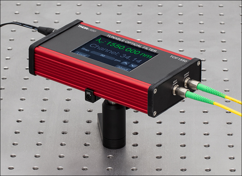
Figure 1.1 The TOF1550 is mounted to an optical table using an ECM325 mounting clamp.
Click to Enlarge
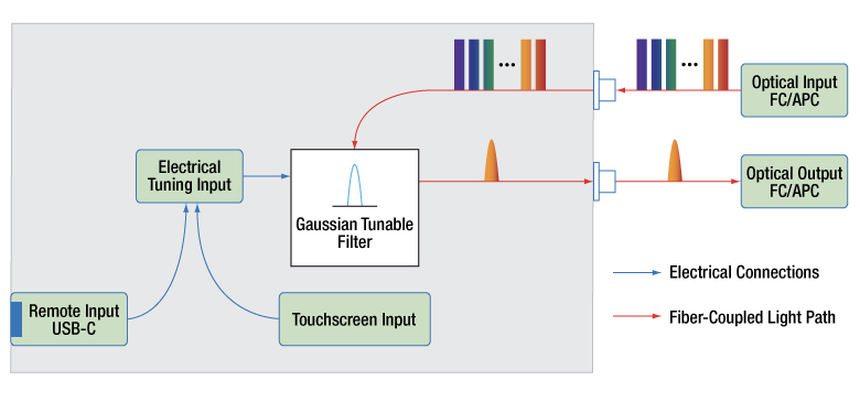
Figure 1.2 The functions of the TOF digital tunable bandpass filters are shown here. An input optical signal is input using the narrow-key FC/APC fiber port and is then filtered based on the setting given using the touchscreen on the device or using the remote commands. The filtered signal is then output through another narrow-key FC/APC fiber port. Please see the manuals for more operation information.
Features
- Tunable, Gaussian Bandpass Filter for O-Band (Item # TOF1310) or C-Band (Item # TOF1550) Operation
- FC/APC Narrow Key (2.0 mm) Fiber Input and Output
- Ideal for DWDM ITU Grid Channel Spacing Applications (Item # TOF1550)
- <3.5 dB (2.5 dB Typical) Insertion Loss at 1310 nm (Item # TOF1310) or 1550 nm (Item # TOF1550)
- Remote Operation Through USB Type-C Port
Applications
- Dense Wavelength Division Multiplexing (DWDM)
- Spectral Response Characterization
- Out-of-Band ASE Suppression
- Receiver Testing
The TOF filters are tunable Gaussian bandpass filters designed to operate with telecommunication O-band (1265 - 1355 nm, Item # TOF1310) or C-band (1527 - 1567 nm, Item # TOF1550) signals. If a broadband optical signal is input, only the passband around the center wavelength will be transmitted. The filter can also be used in a laboratory or production environment as an aid in optical signal selection, monitoring and diagnosis of an optical communication system, characterizing spectral response of detection or amplification systems, or as an amplified stimulated emission filter to enhance a laser's signal-to-noise ratio.
Remote Operation
In addition to operating the TOF bandpass filters using the touchscreen interface on the device, the USB Type-C port and the included USB cable can be used to remotely operate the filters. See the Operation tab for more details. The TOF filter will appear as a serial (COM) port which can be accessed and run using the supplied driver. Any computer that can communicate via a serial port can operate the filter remotely. See the Operation tab for more details.
Mounting Options
The TOF tunable bandpass filters utilize Thorlabs' EEET6011 compact aluminum housing enabling the device to be mounted using the compatible mounting equipment such as the ECM125 and ECM325 (shown in Figure 1.1) aluminum clamps. The housing features silicone rubber bezels to provide surfaces with higher friction than the aluminum housing and protect the faces from scratches.

Click for Details
Figure 2.1 チューナブルバンドパスフィルタTOF1550の図面
| Item # | TOF1310 | TOF1550 |
|---|---|---|
| Wavelength Tuning Range | 1265 - 1355 nm | 1527 - 1567 nm |
| Passband Width @ -1 dBa | ≥ 0.12 nm (21.0 GHz) | ≥ 0.12 nm (15.0 GHz) |
| Passband Width @ -3 dBa | ≥ 0.2 nm (34.9 GHz) | ≥ 0.21 nm (26.2 GHz) |
| Passband Width @ -20 dBa | ≤ 0.8 nm (139.7 GHz) | ≤ 0.77 nm (96.1 GHz) |
| Insertion Lossa,b,c | < 3.5 dB (2.5 dB Typical) | < 3.5 dB (2.5 dB Typical) |
| Polarization Dependent Loss | < 0.5 dB (0.3 dB Typical) | < 0.3 dB |
| Non-Adjacent Isolationa | ≥ 25 dB | ≥ 27 dB |
| Chromatic Dispersion (Absolute) | - | < 10 ps/nm |
| Polarization Mode Dispersion | - | < 0.1 ps |
| Wavelength Tuning Resolution | < 40 pm (7 GHz) | < 12 pm (1.5 GHz) |
| Wavlength Setting Error (Absolute) | 175 pm (30.6 GHz) | < 32 pm (4 GHz) |
| Wavelength Setting Repeatability | ±10 pm (1.7 GHz) | ±8 pm (1 GHz) |
| Wavelength Temperature Dependence (Absolute) | < 5 pm/°C (1 pm/°C Typical) | < 1 pm/°C |
| Return Loss | 30 dB | >40 dB |
| Maximum Input Optical Power | 500 mW (27 dBm) | 300 mW (24.78 dBm) |
| Fiber Specifications | ||
| Fiber Type | SMF-28 | |
| Fiber Length | 70 ± 10 cm | |
| Environmental Conditions | ||
| Operating Temperature | -5 to 65 °C | -5 to 65 °C |
| Storage Temperature | -40 to 85 °C | -40 to 85 °C |
| Operating Relative Humidity | 5 to 85% | 5 to 85% |
| Storage Relative Humidity | 5 to 95% | 5 to 95% |
Figures 3.1 to 3.5 show the sample performance plots for the TOF1310 tunable bandpass filter.
Click to Enlarge
Click for Raw Data
Figure 3.2 The plot above shows a detailed view of the transmission of the TOF1310 filter at 1310 nm. The transmission is found by measuring the insertion loss.
Click to Enlarge
Click for Raw Data
Figure 3.1 The plot above shows the transmission of the TOF1310 tunable filter with the passband tuned to five different center wavelengths: 1270, 1290, 1310, 1330, and 1350 nm. The transmission is found by measuring the insertion loss.
Click to Enlarge
Figure 3.4 The plot above shows the wavelength setting error over the entire tuning range for the TOF1310 bandpass filter.
Click to Enlarge
Figure 3.3 The passband width of the TOF1310 versus wavelength measured for -1, -3, -10, and -20 dB attenuation.
Click to Enlarge
Figure 3.5 Shown above is the insertion loss of the TOF1310 filter over the operating wavelength range defined at the peak of the filter transfer function.
Figures 3.6 to 3.11 show the sample performance plots for the TOF1550 tunable bandpass filter.

Click to Enlarge
Click for Raw Data
Figure 3.7 The plot above shows a detailed view of the transmission of the TOF1550 filter at 1550 nm. The transmission is found by measuring the insertion loss.
Click to Enlarge
Click for Raw Data
Figure 3.6 The plot above shows the transmission of the TOF1550 tunable filter with the passband tuned to five different center wavelengths: 1530, 1540, 1550, 1560, and 1567 nm. The transmission is found by measuring the insertion loss.
Click to Enlarge
Figure 3.9 The plot above shows the wavelength setting error over the entire tuning range for the TOF1550 bandpass filter.
Click to Enlarge
Figure 3.8 The passband width of the TOF1550 versus wavelength measured for -1, -3, and -20 dB attenuation.
Click to Enlarge
Figure 3.11 The plot above shows the non-adjacent channel isolation, which is the isolation provided for channels that are not immediately next to the selected channel on the ITU grid. For example, if channel 31 is selected to be the passband, then the isolation for channels 14 - 29 and 33 - 63 would be ≥27 dB.

Click to Enlarge
Figure 3.10 Shown above is the insertion loss of the TOF1550 filter over the operating wavelength range defined at the peak of the filter transfer function.
チューナブルバンドパスフィルタTOFシリーズは、前面のタッチパネルインターフェースから直接、または付属のUSB Type-Cケーブルとデバイス側面のポートを使用してリモートで制御することができます。
目次

Click to Enlarge
Figure 4.2 上のメイン表示画面には、チューニングパラメータとして選択されたチャンネルが表示されます。表示される波長はチャンネルの中心波長に相当します。

Click to Enlarge
Figure 4.1 上のメイン表示画面は、チューニングパラメータとして選択された中心波長を示しています。
Click to Enlarge
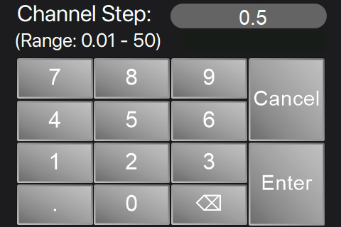
Figure 4.4 チャンネルステップ選択画面です。チャンネルステップの増分は0.01~50まで設定できます。

Click to Enlarge
Figure 4.3 ターゲット波長画面では、通過帯域の中心波長を直接入力可能です。
タッチパネル操作
チューナブルバンドパスフィルタTOFシリーズのタッチパネルインターフェースでは、ターゲットの中心波長「λc」、または通過帯域のチャンネルを直接選択することができます(型番TOF1550)。中心波長は通過帯域の中心に、チャンネル番号はDWDM ITUグリッドチャンネル番号に相当します(TOF1550)。TOF1550の動作範囲内の100 GHz間隔のITUグリッドに基づくチャンネルリストはTable 4.5をご覧ください。
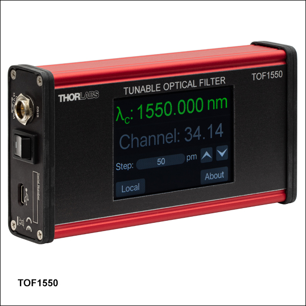
Figure 4.1と4.2に示すインターフェースのメイン画面には、中心波長、チャンネル、ステップ値の設定が表示されます。選択されたパラメータ(「λc」または「Channel」)は緑色でハイライトされ、「ステップ」値の単位は、Figure 4.1と4.2に示すように、選択されたパラメータに応じてpmまたはチャンネル番号に変更されます。ステップ行の上下の矢印を押すと、選択したパラメータがステップの量だけ増減します。 「λc」または「Channel」がアクティブの場合、目的の行を選択することで、ターゲットの中心波長と波長ステップ、またはチャンネルとチャンネルステップを手動で入力することができます。
Figure 4.3は中心波長を手動入力する画面です。中心波長は1265 nm~1355 nm (TOF1310)または1527 nm~1567 nm (TOF1550)まで、最小分解能1 pmで調整できます。同様に、チャンネル番号も14~63まで、最小0.01刻みで入力できます(TOF1550)。
中心波長またはチャンネル番号のステップ設定は、中心波長またはチャンネル番号のいずれかが選択されている場合にのみ入力可能です。Figure 4.4はチャンネルステップ設定画面で、Figure 4.2のチャンネル行を選択したときに編集されます。チャンネルのステップは0.01~50の範囲で0.01刻み(1GHz)で調整でき、波長ステップは 1 pm~50 000 pm の範囲で最小 1 pm 刻みで調整できます。
Table 4.5では、100 GHz間隔のITUグリッドで、フィルタTOF1550の動作範囲内にあるチャンネルを、対応する周波数(GHz)と波長(nm)とともに示しています。
| Table 4.5 ITU Grid Channelsa | ||||||||
|---|---|---|---|---|---|---|---|---|
| Channel # | Frequency (GHz) | Wavelength (nm) | Channel # | Frequency (GHz) | Wavelength (nm) | Channel # | Frequency (GHz) | Wavelength (nm) |
| 14 | 191 400 | 1566.31 | 31 | 193 100 | 1552.52 | 48 | 194 800 | 1538.98 |
| 15 | 191 500 | 1565.50 | 32 | 193 200 | 1551.72 | 49 | 194 900 | 1538.19 |
| 16 | 191 600 | 1564.68 | 33 | 193 300 | 1550.92 | 50 | 195 000 | 1537.40 |
| 17 | 191 700 | 1563.86 | 34 | 193 400 | 1550.12 | 51 | 195 100 | 1536.61 |
| 18 | 191 800 | 1563.05 | 35 | 193 500 | 1549.32 | 52 | 195 200 | 1535.82 |
| 19 | 191 900 | 1562.23 | 36 | 193 600 | 1548.52 | 53 | 195 300 | 1535.04 |
| 20 | 192 000 | 1561.42 | 37 | 193 700 | 1547.72 | 54 | 195 400 | 1534.25 |
| 21 | 192 100 | 1560.61 | 38 | 193 800 | 1546.92 | 55 | 195 500 | 1533.47 |
| 22 | 192 200 | 1559.79 | 39 | 193 900 | 1546.12 | 56 | 195 600 | 1532.68 |
| 23 | 192 300 | 1558.98 | 40 | 194 000 | 1545.32 | 57 | 195 700 | 1531.90 |
| 24 | 192 400 | 1558.17 | 41 | 194 100 | 1544.53 | 58 | 195 800 | 1531.12 |
| 25 | 192 500 | 1557.36 | 42 | 194 200 | 1543.73 | 59 | 195 900 | 1530.33 |
| 26 | 192 600 | 1556.56 | 43 | 194 300 | 1542.94 | 60 | 196 000 | 1529.55 |
| 27 | 192 700 | 1555.75 | 44 | 194 400 | 1542.14 | 61 | 196 100 | 1528.77 |
| 28 | 192 800 | 1554.94 | 45 | 194 500 | 1541.35 | 62 | 196 200 | 1527.99 |
| 29 | 192 900 | 1554.13 | 46 | 194 600 | 1540.56 | 63 | 196 300 | 1527.22 |
| 30 | 193 000 | 1553.33 | 47 | 194 700 | 1539.77 | - | - | - |
リモート操作とドライバのダウンロード

Click to Enlarge
Figure 4.6 TOFシリーズのリモート操作中は、波長、チャンネル、ステップの各ボタンはグレーアウトしています。
ドライバのダウンロード
ドライバのバージョン1.0 (2024年9月16日)
チューナブルフィルタTOF1310とTOF1550のドライバは下記リンクよりダウンロードいただけます。
チューナブルフィルタTOFシリーズは、付属のUSBケーブルを使用して、デバイスの側面パネルにあるUSB Type-Cポートからリモート操作することができます。リモート操作モード中は、タッチパネルのチューニングパラメータにはアクセスできなくなり、Figure 4.6のように暗くなります。フィルタTOFシリーズは、接続されたPC上の仮想シリアルCOMポートとして表示されます。チューニングパラメータは、IEEE 488.2 Standard Commands for Programmable Instruments (SCPI)にならった構文のコマンドを送信することで調整することができます。シリアルポートの設定は、以下のパラメータに設定する必要があります。
- Baud Rate: 115 200
- Bit: 8
- Parity: None
- Stop Bits: 1
- Flow Control: None
チューナブルバンドパスフィルタのリモート操作の詳細については、 マニュアルを参照してください。

| Callout | Description |
|---|---|
| 1 | Input, FC/APC (2.0 mm Narrow Key) Connector |
| 2 | Output, FC/APC (2.0 mm Narrow Key) Connector |

| Callout | Description |
|---|---|
| 1 | 15 VDC Mini-XLR Connector for DS15 Power Supply |
| 2 | Power Switch |
| 3 | USB Type-C Connector for Remote Operation and/or Powering the Device |
Click to Enlarge
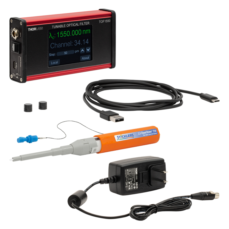
Figure 6.1 チューナブルバンドパスフィルタTOFシリーズは、上のコンポーネントとともに発送されます。
デジタルバンドパスフィルタTOFシリーズには下記が含まれます。
| Posted Comments: | |
Christopher Ebbers
(posted 2025-05-02 01:27:25.02) 1. How does the tunable filter operate (is there a MEMS grating, a rotation in a Lyot type filter, or some other mechanism)?
2. What is the speed at which the wavelengths can be changed?
3. Is there a settling time?
Thank you
Chris tdevkota
(posted 2025-05-07 09:21:47.0) Thank you for contacting Thorlabs. The tunable bandpass filter is based on MEMS-actuated grating designs, providing high-speed wavelength tunability without moving parts. I have reached out to you directly to further discuss your application. |

 ズーム
ズーム- Wavelength Tuning Range of 1265 - 1355 nm
- <3.5 dB (2.5 dB Typical) Insertion Loss at 1310 nm
Thorlabs’ TOF1310 filter is a tunable Gaussian bandpass filter designed to operate with telecommunication O-band (1265 - 1355 nm) signals. The center wavelength of the bandpass can be tuned to any position within the operating wavelength range by selecting the wavelength directly.
The TOF1310 touchscreen allows the target center wavelength "λc" to be specified directly within the operating range of 1265 - 1355 nm. This passband can then be adjusted using the "Step" up and down arrows. The step size for the wavelength or channel can be adjusted in steps as small as 1 pm, though the tuning resolution of the TOF1310 filter passband is <40 pm. See the Specs tab for typical performance specifications.
| Table G1.1 Specifications | |||||||||
|---|---|---|---|---|---|---|---|---|---|
| Item # | Wavelength Tuning Range | Passband Width @ -1 dBa | Passband Width @ -3 dBa | Passband Width @ -20 dBa | Insertion Lossa,b,c | Polarization Dependent Loss | Non-Adjacent Isolationa | Maximum Input Power | |
| TOF1310 | 1265 - 1355 nm | ≥0.12 nm (21.0 GHz) |
≥0.2 nm (34.9 GHz) |
≤0.8 nm (139.7 GHz) |
<3.5 dB (2.5 dB Typical) |
<0.5 dB (0.3 dB Typical) |
≥25 dB | 500 mW (27 dBm) |
|

 ズーム
ズーム- Wavelength Tuning Range of 1527 - 1567 nm
- 50 GHz Dense Wavelength Division Multiplexing (DWDM) ITU Grid
- <3.5 dB (2.5 dB Typical) Insertion Loss at 1550 nm
Thorlabs’ TOF1550 filter is a tunable Gaussian bandpass filter designed to operate with telecommunication C-band (1527 - 1567 nm) signals on a dense wavelength division multiplexing (DWDM) ITU grid. The center wavelength of the bandpass can be tuned to any position within the operating wavelength range by selecting either the wavelength directly or a channel on the ITU grid. If multiple DWDM channels are input into the filter, only the selected channel will be transmitted while all others will be blocked.
The TOF1550 touchscreen allows the target center wavelength "λc" to be specified either directly within the operating range of 1527 - 1567 nm or by selecting a desired ITU grid channel from 14 to 63. This passband can then be adjusted using the "Step" up and down arrows. The step size for the wavelength or channel can be adjusted in steps as small as 1 pm or 0.01 channel (1 GHz), respectively, though the tuning resolution of the TOF1550 filter passband is <12 pm (1.5 GHz). See the TOF1550 Operation tab for more details on adjusting the filter parameters and the Specs tab for typical performance specifications.
| Table G2.1 Specifications | |||||||||
|---|---|---|---|---|---|---|---|---|---|
| Item # | Wavelength Tuning Range | Passband Width @ -1 dBa | Passband Width @ -3 dBa | Passband Width @ -20 dBa | Insertion Lossa,b,c | Polarization Dependent Loss | Non-Adjacent Isolationa | Maximum Input Power | |
| TOF1550 | 1527 - 1567 nm | ≥0.12 nm (15.0 GHz) |
≥0.21 nm (26.2 GHz) |
≥0.77 nm (96.1 GHz) |
<3.5 dB (2.5 dB Typical) |
<0.3 dB | ≥27 dB | 300 mW (24.78 dBm) |
|