 Products Home / オプトメカニクス用部品 / 光学ポストアセンブリー / Ø38 mm(Ø1.5インチ)ポストアセンブリー / Ø38 mm(Ø1.5インチ)ポスト用コンストラクションアクセサリー
Ø38 mm(Ø1.5インチ)ポスト用コンストラクションアクセサリー
- Ideal for Securing Optomechanics to Our Ø1.5" Stainless Steel Posts
- Rigid Construction Provides Stability for Sensitive Alignment Assemblies
#8 (M4) Counterbore
1/4"-20 (M6) Tap
Rotating 8-32 (M4) Mounting Stud
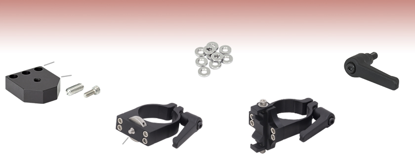
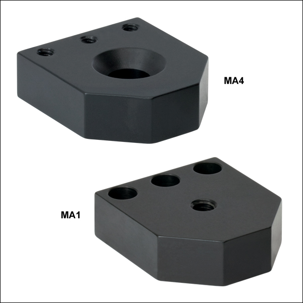
MA1
Post Mounting Adapter
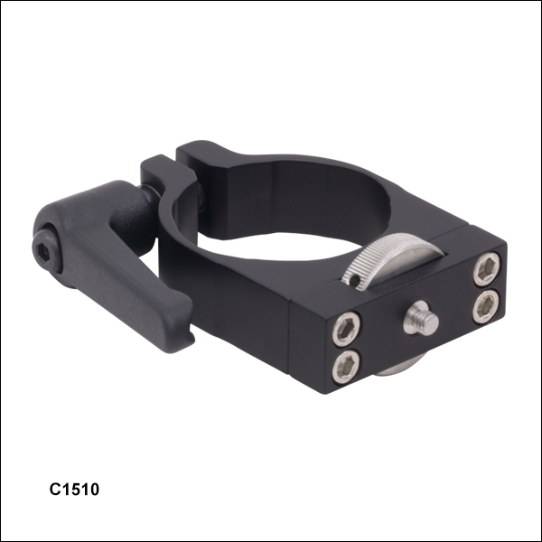
C1510
Compact Post Clamp
CH1530
30 mm Cage System Adapter
SD1
Adapter Ring
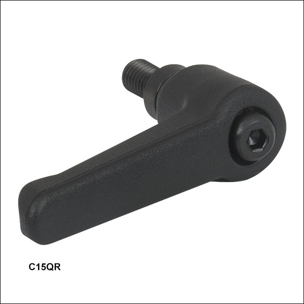
C15QR
Quick-Release Handle


Please Wait

| Ø1.5" Post Accessories |
|---|
| Construction Accessories |
| V-Mounts |
| Mounting Plates |
| Brackets / Platforms |
| Mirror Mounts |
これらのポスト取付けアダプタを用いて、当社のほぼすべてのオプトメカニクスをØ38 mm(Ø1.5インチ)ポストに直接取り付けられます。
小型ポストクランプ
小型ポストクランプC1510/Mは、取付け用M4タップ穴付きの光学マウントをØ38 mm(Ø1.5インチ)ポストに取り付けます。光学マウントの角度は刻み目(ローレット)付きノブで簡単に調整できます。
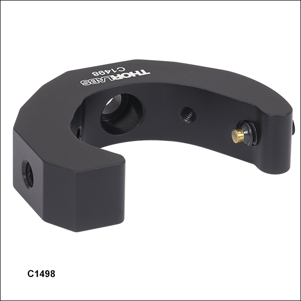
スリップオン式ポストクランプ
スリップオン式ポストクランプは、M6ネジ切り付き部品をØ38 mm(Ø1.5インチ)ポストに取り付けます。ザグリ穴用アダプターリングSD1を用いれば、M4ネジ切り付き部品も取り付けられます。
ケージクランプマウント
ケージクランプマウントCH1530/M、CH1560/M、CV1530/Mは、クイック接続機構で30 mmまたは60 mmのケージアセンブリをØ38 mm(Ø1.5インチ)ポストに水平または垂直方向に固定します。
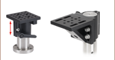
ポスト用アダプタ
ポスト用取付けアダプタは、Ø38 mm(Ø1.5インチ)ポストの取付けプラットフォームとして機能します。M6およびM4のタップ穴とザグリ穴を組み合わせて配置されています。
簡単脱着ハンドル
クランプを簡単かつ確実にポストに固定できる簡単脱着ハンドルもご用意しています。取付けは、ポストクランプの1/4"-20またはM6固定ネジと交換するだけです。長さ51.4 mmのハンドルにはM6ネジ付きのスタッドがあり、ハンドルを回転させて簡単に取り付けることができます。スリップオン式クランプC1498/Mとポスト用アダプタを除くすべての下記掲載製品に対応しています。
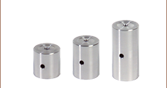
高さ調整カラー
高さ調整カラーPSHA/Mはポストに取り付けられた部品の高さを精密に調整します。Ø38 mm(Ø1.5インチ)ポストに取付け可能で、垂直方向に最大8.2 mm調整可能です。
| Posted Comments: | |
ludoangot
(posted 2017-04-10 11:19:47.743) What are the recommended and maximum torques that can be applied on the C1510(/M)? I am planning to add a 12.7mm post on the mounting stud and an c-mount camera to have a throw of about 130mm from the 1.5" post. Or can you recommend another solution to have an at least 120mm throw from a post (or rail)? tfrisch
(posted 2017-04-27 03:01:16.0) Hello, thank you for contacting Thorlabs. I will contact you directly about solutions for mounting off of a post. You may also want to consider optical rails. apalmentieri
(posted 2010-01-20 14:42:35.0) A response from Adam at Thorlabs to n.kunst: The measurements in the pdf of the MA4/M are correct. Unfortunately, this product would not fit on the T12XYZ/M. We could make a custom version that would align two of the tapped holes to the spacing of the T12XYZ/M for compatible mounting. Another option, if you do not need 12.7mm travel, would be to use the MS3. The MS3 contains two tapped M4 holes that will line up with the tapped holes on the MA4/M. My only concern would be the amount of equipment you would be mounting to the MA4/M. The vertical load capcity of the MS3 is 2.5lbs and the horizontal load capcity is 7lbs. n.kunst
(posted 2010-01-20 10:06:08.0) Are the measurements in the pdf of MA4/M correct metric?
Does it fit on the t12xyz/m ?
plsease respond to my email: n.kunst@science.ru.nl
thanks,
Nick nkaddy
(posted 2008-06-18 09:38:46.0) Superb! A great company policy - Im very pleased to hear that! Tyler
(posted 2008-06-04 11:10:04.0) A response from Tyler at Thorlabs to nkaddy: Although we dont have a formal procedure, both the idea and the customers name are passed onto the design engineer. If the idea results in a new product or a redesigned product we often involve the customer in the testing of the prototype(s) and the customer is usually given the prototype version that is put into production. We chose to make this forum public because it was our hope that people like you would share their experiences with the science community. So even if the C1500 isnt redesigned, your idea may help other members of the science community improve their experimental setup. Thorlabs is not only interested in improving our product line, but in finding ways for us and our customers to contribute to the knowledge base of the scientific community. nkaddy
(posted 2008-06-04 08:57:56.0) To Tyler: Perhaps then you should have an incentives scheme, where if the feedback is useful you offer to make one of the items for the person suggesting it? Tyler
(posted 2008-05-22 10:18:20.0) A response from Tyler at Thorlabs to nkaddy: Thank you for sharing your solution with us and all the other users of this part. The information you provided has been passed on to the design engineers. Please continue to use this feedback forum to let us know about your experiences in the lab. We will use the information to try and make products that make your lab more productive. nkaddy
(posted 2008-05-21 11:38:37.0) Hi acable, we ended up tapping an M2 thread into the side of the C1500 and added a spacer to the M4 thread projecting from the front so that the opto-mech can be tightend with the wheel still able to move freely. Once in position, an M2 screw in the newly tapped thread locks the wheel. I also tried thrust washers, they were OKish but not as effective and definately not set and forget. acable
(posted 2008-04-05 09:41:47.0) The way i use the C1500 actually allows a piece of opto-mech with a tapped hole (#8-32 or M4) to be rotated to any orientation. I snug the mount down to the C1500 but leave it just loose enough to rotate, once i have the orientation i want i then use a 5/64" hex wrench inserted into one of the side holes on the locking wheel to full tighten the device. While this takes two hands, the result is a very stable mounting arrangement that allows the mating optical mount to be secured at an angle. nkaddy
(posted 2008-04-05 08:12:31.0) Hi Laurie, Please email me for the details of the changes we made to the product to make it considerably more flexible. Laurie
(posted 2008-03-25 10:29:14.0) Response from Laurie at Thorlabs to nkaddy: Thank you for your suggestion on how to improve this product! We always enjoy receiving such input from the users of our products. I have passed your suggestion on to our mechanics design team so that they can consider it. Thanks again for taking the time to contact us! nkaddy
(posted 2008-03-25 10:15:24.0) I like the idea of the C1500 but was disappointed to find that the wheel doesnt rotate once the mount is fixed into place. If you had a mount that would fix first and then could be rotated with the four holes actually providing locking screws I think youd have a better product. |

 ズーム
ズーム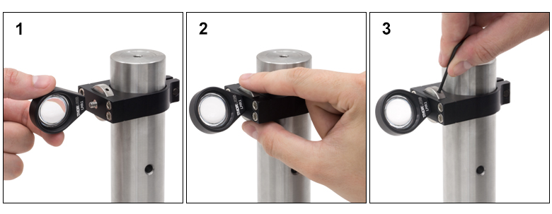
- M4タップ穴付き光学マウントをØ38 mm(Ø1.5インチ)Pシリーズのポストに装着
- 刻み目(ローレット)付きノブで角度の粗調整が可能
- ノブ上の4つの穴でしっかり固定(詳細は右写真参照)
- 付属の簡単脱着ハンドルでØ38 mm(Ø1.5インチ)ポストに容易に装着
小型ポストクランプC1510/Mは、M4タップ穴付きの光学マウントをØ38 mm(Ø1.5インチ)ポストに取り付けます。各小型ポストクランプには、Ø38 mm(Ø1.5インチ)ポストに取り付ける際に使用する簡単脱着ハンドルC15QR/Mが付属します。交換用の簡単脱着ハンドルは下記から別途追加購入いただけます。必要に応じてこのハンドルを取り外し、長さ12 mm以上のM6キャップスクリュと交換できます。
右の写真をクリックすると、レンズマウントLMR1(/M)の取り付け方法を示した3枚の写真が表示されます。光学マウントの角度を設定した後(写真1参照)、刻み目(ローレット)付きノブを使ってデバイスをC1510(/M)にねじ込みます(写真2参照)。最後は、2 mm六角レンチまたはボール(六角)ドライバをノブ上の4つの穴に挿入してさらに締め付けることができます(写真3参照)。これにより最終段階で締付けトルクを追加できます。
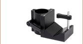
 ポスト用スリップオン式ポストクランプ")
 ズーム
ズーム
- M6またはM4ネジ切り付き部品を当社のØ38 mm(Ø1.5インチ)Pシリーズポストに装着
- ポストを傷つけない真鍮製固定ネジでポストに固定
- M4ザグリ穴付き光学マウント用に、M4タップ穴2つ付き
- M6ネジ切り付き部品の取付け用に1/4”ザグリ穴付き
- M4ネジ切り付き部品の取付け用には1/4”ザグリ穴にアダプタSD1を使用
右図ではØ50.8 mm(Ø2インチ)の銀製ミラーPF20-03-P01がØ50 mm~Ø50.8 mm(Ø2インチ)用ミラーマウントKS2に取り付けられた状態で、M4ネジ切り穴を利用してポストクランプC1498(/M)に取り付けられています。
ポスト用ケージクランプ、水平方向取付け用")
 ズーム
ズーム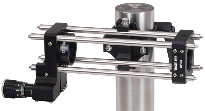
Click to EnlargeFigure 212A クランプCH1530(/M)を用いてØ38 mm(Ø1.5インチ)ポストに取り付けられた30 mmケージシステム
- 30 mmまたは60 mmのケージシステムをØ38 mm(Ø1.5インチ)ポストに固定
- クイック接続機構によりØ6 mmケージロッドを使用するケージアセンブリを簡単に脱着
- ケージ取付け部は5 mmキャップスクリュによって作動
- Ø38 mm(Ø1.5インチ)ポストへの取付けを容易にする簡単脱着ハンドルが付属
ケージクランプCH1530/Mは30 mmケージシステムを、CH1560/Mは60 mmケージシステムを、それぞれØ38 mm(Ø1.5インチ)ポストに取り付ける際にお使いいただけます。クイック接続機構によってケージセグメントを簡単に脱着することができます。ケージセグメントを固定するには、3 mm六角レンチ(またはボールドライバ)を用いてケージ取付け部の六角キャップスクリュを締め付けます。 各ケージクランプには、Ø38 mm(Ø1.5インチ)ポストへの取付け用に簡単脱着ハンドルC15QR/Mが付属しています。この簡単脱着ハンドルは、別途追加でもご購入いただけます。 必要に応じてハンドルを取り外し、代わりに長さ12 mm以上のM6キャップスクリュをご使用いただけます。
Figure 212Aでは、CH1530(/M)で4本のケージロッドER6、Z軸移動マウントSM1ZA、ケージプレートCP33T(/M)で構成されたケージシステムを保持しています。このシステムは、適切な焦点距離のレンズをZ軸マウントおよびケージプレートに配置して、ビーム径を拡大もしくは縮小する望遠鏡として使用することができます。
ポスト用ケージクランプ、垂直方向取付け用")
 ズーム
ズーム- 30 mmケージシステムを当社のØ38 mm(Ø1.5インチ)ポストに取付け
- ケージシステムを垂直または水平に取付け可能
- クイック接続機構でケージシステムを簡単に脱着
- 耐荷重6.8 kg
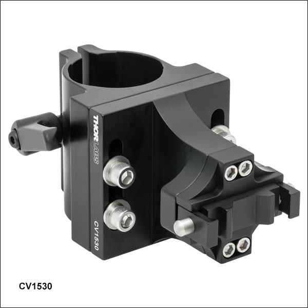
ケージクランプCV1530/Mは、30 mmケージシステムを当社のØ38 mm(Ø1.5インチ)ポストに垂直に取り付けます。クイック接続機構でケージセグメントを脱着します。ケージセグメントを固定するには、3 mmの六角レンチまたはボール(六角)ドライバでケージクランプ機構のキャップスクリュを締め付けます。各ケージクランプには、Ø38 mm(Ø1.5インチ)ポストに取り付ける際に使用する簡単脱着ハンドルC15QR/Mが付属します。追加の簡単脱着ハンドルは別途ご購入いただけます。必要に応じてこのハンドルを取り外し、長さ12 mm以上のM6キャップスクリュと交換できます。
この垂直ケージクランプは水平ケージクランプに変換することができます。その際は、3 mmの六角レンチまたはボールドライバでケージクランプ側面に付いている4個のキャップスクリュを緩め、前面プレートを90°回転させてキャップスクリュを再び締め付けます。
16 mmおよび60 mmケージシステム用にクランプマウントCV1530/Mの特注品もご注文可能です。詳細については当社までお問い合わせください。
ポスト用アダプタ")
 ズーム
ズーム
- 幅広い種類の光学素子や移動ステージを当社のØ38 mm(Ø1.5インチ) Pシリーズポスト に装着するプラットフォームとして使用
- M6のネジ切り穴、M4のネジ切り穴やザグリ穴など様々な組み合わせの取付け穴
右図ではØ25.4 mm(Ø1インチ)超安定ミラーマウントPOLARIS-K1Eが、ポスト用アダプタMA4/MにM4のネジ切り穴を利用して取付けてあります。 ここではアダプタMA4/MのM6用の貫通穴が、Ø38 mm(Ø1.5インチ)のPシリーズのポストのM6ネジ切り部への接続用に使用されています。

 ズーム
ズーム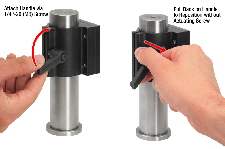
Click for Details
Figure 528A
左:ポスト取付け用クランプC1511(/M)に取り付けられた簡単脱着ハンドルC15QR(/M)。
右:ハンドル位置を回転するには後方に引いてください。
- ポストクランプの位置決めが素早く、繰り返し行える簡単脱着ハンドル
- M6クランプネジ付きのØ25.0 mm~Ø25.4 mmポスト用クランプまたはØ38 mm(Ø1.5インチ)ポスト用クランプに対応
- クランプの固定/固定解除に対する優れた操作性と使用感
- ハンドルは固定ネジを動かさずに回転可能
- M6ネジ
簡単脱着式ハンドルC15QR/Mを用いると、フレクシャー機構によるØ25.0 mm~Ø25.4 mmポスト用クランプまたはØ38 mm(Ø1.5インチ)ポスト用クランプを簡単にしっかりと固定できます。フレクシャー機構を用いた多くのポスト用クランプでは、ポストに固定するのにキャップスクリュが用いられますが、その調整にはボール(六角)ドライバが必要です。取り付けた荷重によっては、ボールドライバを使用するのが困難な場合があり、ときには危険な場合さえあります。簡単脱着式ハンドルを用いると、クランプを締めたり緩めたりするトルク量を手で確実に調整できるため、この種の問題を軽減することができます。また、ボールドライバを必要とせずにクランプを素早く固定できるため、組立てや調整に要する時間も短縮できます。
ハンドルはポストクランプのM6固定ネジと簡単に交換することができ、長さ51.4 mmのハンドルを回転させると係合するM6 x 1.0ネジ付きスタッドが付いています。ハンドルを締めてクランプをポストに固定したあとは、内部のラチェット機構により、固定されたスタッドを動かさずにハンドルの回転位置を調整できます。ハンドルは、外側に引くだけでネジ付きスタッドとの係合が外れ(Figure 528A参照)、ご希望の位置までハンドルを回転することができます。このためハンドルはどの位置からでも操作可能です。
ポスト用高さ調整カラー")
 ズーム
ズーム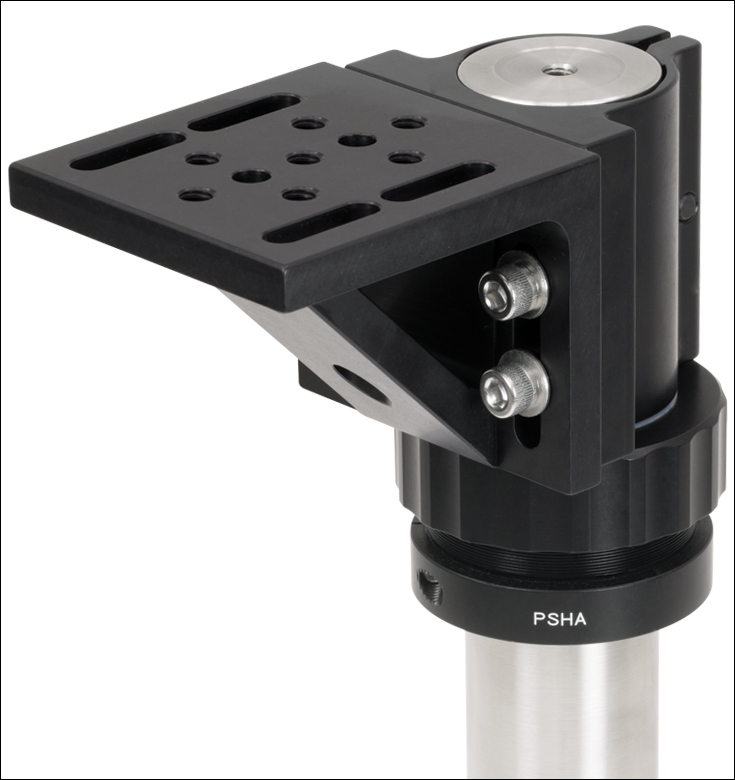
- 移動量:1回転につき0.64 mm
- 垂直方向の調整範囲:8.2 mm
Ø38 mm(Ø1.5インチ)ポスト用高さ調整カラーPSHA/Mは、ポストに取り付けられた部品の高さ調整に便利です。作動リングはアクセスが簡単で、1回転につき高さ0.64 mmの微調整を行います。 このカラーに取り付けられた部品の高さを変えずに、自由に回転することもできます。
使用するにはØ38 mm(Ø1.5インチ)ポストの上にカラーをかぶせ、所望の高さに保持します。カラーの位置はフレクシャークランプをM6キャップスクリュで締め付けて固定します。カラーの上にオプトメカニクスを置き、作動リングを回して部品の高さを調整します。高さを固定するには止めネジ(セットスクリュ)を2 mm六角レンチで締め付けます。カラー上部のナイロン製のリングは高さ調整時の摩耗を防ぎます。