 Products Home
部分反射リフレクター、インラインファイバー型
- Partial Reflectors with Internal Reflective Coating
- 1450 nm - 1650 nm Wavelength Range
- 67:33 or 10:90 Reflection Ratio (R:T)
- Available with FC/PC or FC/APC Connectors
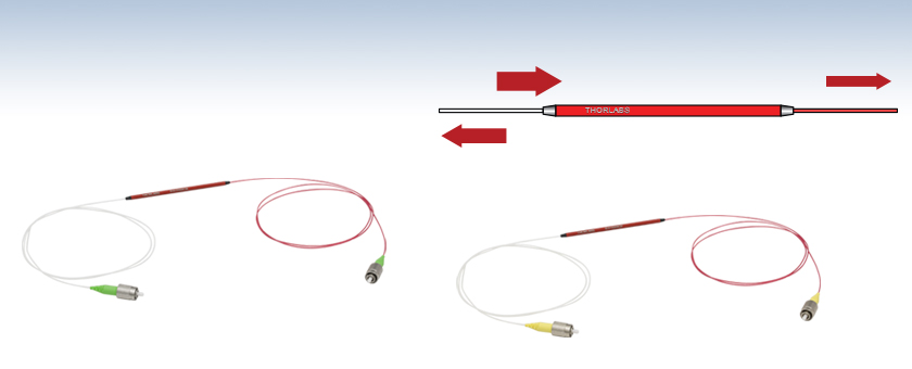
Input Light
Transmitted Light
Reflected Light
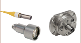
RW1550R2A
10:90 Partial Reflector with FC/APC Connectors
RW1550R3F
67:33 Partial Reflector with FC/PC Connectors


Please Wait
特長
- インラインファイバ型の部分反射リフレクタ
- 反射率(R:T)が67:33または10:90の内部反射コーティング
- 波長範囲:1450 nm~1650 nm
- 2.0 mmナローキー付きFC/PCまたはFC/APCコネクタをご用意
当社のインラインファイバ型の部分反射リフレクタは、入射光を部分的に反射します。一部の光は反射して入力端に戻り、それ以外の光は出力部に送られます。これは、一部の入射光が、内部の反射コーティングによって入射部分に戻されるためです。この部分反射リフレクタは、当社のビームスプリッタのコーティング付きパッチケーブルとは異なり、どちらのコネクタ端面にもコーティングが施されていないため、他のパッチケーブルとコネクタ接続することができます。光ファイバーサーキュレータと一緒に使用する際は、ビームスプリッタ型ファイバとしての性能を発揮し(「用途」タブ参照)、往復遅延タイミングの測定などの用途に便利です。
この部分反射リフレクタは、1450 nm~1650 nmのシングルモードの波長範囲に対応し、反射率(R:T)は67:33または10:90をご用意しています。この反射率は、反射光と透過光の比率で、吸収によってデバイス内で消失した光は含まれていません。白いポートが入力部となります。部分反射リフレクタを逆向きに使用することはできませんのでご注意ください。標準品は、下表のとおりFC/PCまたはFC/APCコネクタ付きでご用意しております。ファイバはすべてØ900 µm、長さ0.8 mのHytrel®*チューブで被覆されています。異なる波長やファイバの種類およびR:T比で構成されたカスタムファイバもご用意しています。詳細は当社までお問い合わせください。
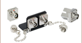
部分反射リフレクタには、フェルール端を埃などから守る保護キャップが2個付属しています。FC/PCコネクタ用のプラスチック製ファイバーキャップCAPFやネジ付き金属キャップCAPFMも、別売りでご用意しています。 パッチケーブル同士を結合する際に各コネクタ付きファイバ端のコアを適切に接合し、後方反射を最小限に抑えることができるアダプタもご用意しています。
*Hytrel®はDuPont Polymers社の登録商標です。

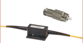
Click to Enlarge
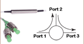
図 1: オールファイバ型ビームスプリッタのセットアップ
オールファイバ型ビームスプリッタ
インラインファイバ型の部分反射リフレクタは、ビームスプリッタ、レーザ共振器、レーザ干渉計など様々なデバイスを構成する際に役立ちます。ファイバは光の一部をファイバに戻し、残りの光は出力ファイバーコネクタを通過させます。
この特性は、オールファイバ型ビームスプリッタを作成する際に特に便利です。ビームスプリッターキューブを用いた自由空間工学系を構築する必要なく光源を分岐することができるからです。図1では光ファイバーサーキュレータとインラインファイバ型部分反射リフレクタだけを用いたシンプルなセットアップをご紹介しております。光は光サーキュレータのポート1に入射されます。部分反射リフレクタはポート2に結合しています。入力光はポート1からポート2に伝送されます。光のおよそ33%がファイバ出力部に送られ、残りの光は反射して入力部に戻り、サーキュレータによってポート3に送られます。
| Posted Comments: | |
Brent Carlson
(posted 2022-10-31 13:56:52.023) Hi, I've purchased and I'm testing the RW1550R3F partial reflector. Maybe I missed it, but I'm wondering what its polarization properties are for the reflected signal. Is it Faraday mirror and reflects at 90 deg? Does it reflect at the same pol as the incident signal? Is it arbitrary? Is the reflected signal depolarized? Any insight/help would be greatly appreciated. jgreschler
(posted 2022-11-01 03:51:59.0) Thank you for reaching out to Thorlabs. The In-Line Fiber Partial Reflectors use single mode fiber, the phase and polarization of the reflected and transmitted signals will have no relationship after exiting the fiber, only relative intensity. user
(posted 2021-07-06 10:51:45.783) For the In-Line Fiber Partial Reflectors, the notes say it cannot be used in the reverse direction. But what happens when light does enter in the reverse direction? For example, is it very lossy? Thanks YLohia
(posted 2021-07-07 02:58:45.0) Thank you for contacting Thorlabs. This product is essentially a 2x2 coupler, except that one output has a highly reflective coating, and the second input is internally terminated. The end product is a 1x1. Therefore, the losses will be quite high when being operated in reverse. Simon Boiviner
(posted 2019-06-18 11:40:52.16) Hi,
Have you any PM version of RW1550R3A component ?
Reagrds,
Simon YLohia
(posted 2019-06-20 08:43:47.0) Hello Simon, thank you for contacting Thorlabs. Quotes for custom items can be requested by emailing techsupport@thorlabs.com. I have reached out to you directly to discuss the possibility of offering this. masahiro.watanabe.ub
(posted 2017-02-22 10:57:16.757) Selection of the reflectance should be allowed. Only R = 67% is not useful. I am looking for inline partial reflector with R = 4%. R = 10% and 33 % would also be useful. tfrisch
(posted 2017-03-02 02:10:01.0) Hello, thank you for sharing your feedback on what other ratios would be useful. I will reach out to you directly about our custom capabilities until we release more versions to our stock. |
| Item #a | Info | Center Wavelength | Bandwidth | Reflectanceb (Click for Plot) | Transmissionc (Click for Plot) | Reflection Ratiod | Fiber Typed | Termination |
|---|---|---|---|---|---|---|---|---|
| RW1550R3F | 1550 nm | ±100 nm | 45.0 ± 4.5% (3.5 ± 0.4 dB) | 22.5 ± 2.5% (6.5 ± 0.5 dB) | 67:33 | SMF-28 | FC/PC | |
| RW1550R3A | FC/APC |
| Item #a | Info | Center Wavelength | Bandwidth | Reflectanceb (Click for Plot) | Transmissionc (Click for Plot) | Reflection Ratio | Fiber Typed | Termination |
|---|---|---|---|---|---|---|---|---|
| RW1550R2F | 1550 nm | ±100 nm | 7.2 ± 2.7% (11.4 ± 2.0 dB) | 65.0 ± 5.0% (1.9 ± 0.1 dB) | 10:90 | SMF-28 | FC/PC | |
| RW1550R2A | FC/APC |