 Products Home
Cシリーズ フォトダイオードパワーセンサー
- Power Ranges Covering 100 pW to 20 W
- Wavelength Ranges Covering 200 nm to 5.5 µm
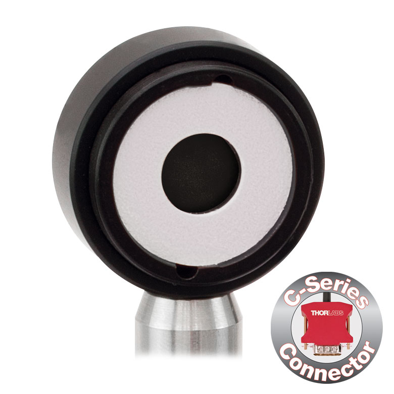
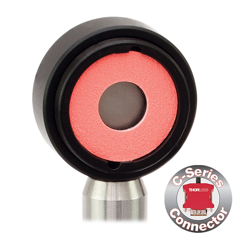
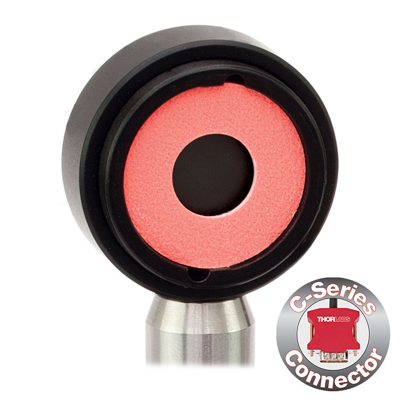
- C-Series Connector for Quick Exchange
S120C
Sensor with IR
Target
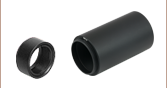
S145C
Integrating Sphere Sensor
Posts and Post Holders Not Included
S140C
Integrating Sphere Sensor
S130C
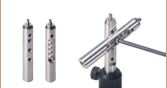
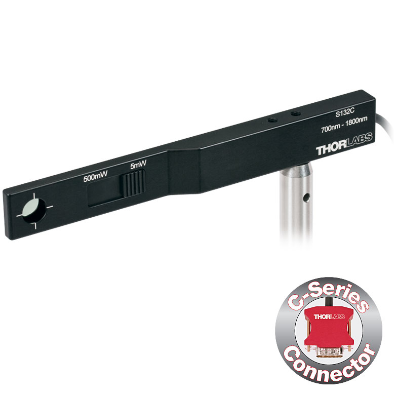
Slim Sensor
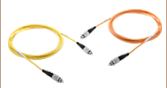
S154C
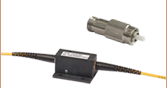
Fiber Sensor
S170C
Microscope Slide
Power Sensor Head
Integrating Sphere Sensors Shown with FC/PC Adapters (Included on Sensors with Apertures ≤Ø12 mm)
Articulating Arm Not Included
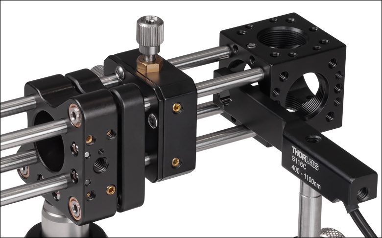
S116C
Compact Slim Sensor


Please Wait
| Power Meter Selection Guide |
|---|
| Sensors |
| Photodiode Power Sensors |
| Thermal Power Sensors |
| Thermal Position & Power Sensors |
| Pyroelectric Energy Sensors |
| Power Meter Consoles |
| Digital Handheld Console |
| Analog Handheld Console |
| Touchscreen Handheld Console |
| Dual-Channel Benchtop Console |
| Complete Power Meters |
| Power Meter Bundles |
| Wireless Power Meters with Sensors |
| Compact USB Power Meters |
| Field Power Meters for Terminated Fibers |
| USB Interfaces, External Readout |
特長
- 高速応答で高分解能
- 迅速にセンサを接続できるCシリーズコネクタ設計
- 高温度警告センサ付き(S130シリーズならびに顕微鏡用スライドセンサS170Cを除く)
- それぞれNISTおよびPTBトレーサブル校正証明書(Certificate of Calibration)付き。校正曲線とセンサ設定は組込み済み
Cシリーズフォトダイオードパワーメーターセンサは、広範囲な光パワーと波長を網羅します。センサは、用途に合わせて標準、薄型、積分球、顕微鏡スライドならびにコンパクトなファイバ用の製品からお選びいただけます。高速応答または高分解能が要求され、平坦なスペクトル応答が不要な用途に適しています。
フォトダイオードパワーメーターセンサには、電磁干渉を避ける強化シールドと、センサのオーバーヒートによる損傷や測定エラーを防ぐ高温度警告センサが付いています(薄型センサS130VC、S130C、S132Cと顕微鏡用スライドセンサS170C、S171Cを除く)。全てのセンサ(コンパクト薄型センサS116C、薄型センサ薄型センサS130VC、S130C、S132Cならびに顕微鏡用スライドセンサS170C、S171Cを除く)には、標準的な光ファイバーパッチケーブルに接続できるファイバーアダプターセットをお使いいただけます(下記をご覧ください)。ほかの種類のファイバーアダプタも別途ご用意しております。
下記のセンサ(S150Cシリーズを除く)はM4または#8-32取付け穴によってØ12 mm~Ø12.7 mm(Ø1/2インチ)ポストに取り付けることができます。ポストおよびポストホルダは別売りです。
互換性
これらのセンサはPM400、PM100D、PM100A、PM5020 などのCシリーズのパワーメーターコンソールと、Cシリーズパワー&エネルギーメーターインターフェイスの多くに取り付け可能です。S150Cシリーズのファイバーセンサは、コネクタ部分に内蔵されていて、コンソールに直接差し込むことができます。
校正
センサーヘッドはそれぞれ校正されており、NISTおよびPTBトレーサブル校正証明書と共に発送されます。校正や認証に関するデータはセンサーコネクタ内に保存されており、接続されたパワーメーターコンソールに自動的にダウンロードされます。
センサのアップグレードサービス
全てのCシリーズのセンサは、Cシリーズのコネクタが付いていない旧タイプのパワーメーターコンソールに対応していません。当社では、お手持ちのセンサを、新しいCシリーズコネクタ付きパワーメーターコンソールとお使いいただけるようアップグレードするサービスを提供しております。注: アップグレード後は、旧タイプのパワーメーターコンソールにはお使いになれません。詳細は当社までお問い合わせください。
再校正サービス
当社では再校正サービスを提供しております。センサ精度維持および測定値の検証のために、定期的な再校正をお勧めしています。校正頻度はご用途にもよりますが、通常1年程度です。再校正の詳細や価格などにつきましては、当社までお問い合わせください。
| Photodiode Sensor Selection Guide | ||||||
|---|---|---|---|---|---|---|
| Housing Type | Standard | Slim | Compact Slim | Microscope Slide | Integrating Sphere | Fiber-Coupled |
| Power Range | 50 nW - 500 mW | 500 pW - 500 mW | 20 nW - 50 mW | 1 nW - 150 mW | 1 µW - 20 W | 100 pW - 20 mW |
| Wavelength Range | 200 - 1800 nm | 200 - 1800 nm | 400 - 1100 nm | 350 - 1100 nm | 350 - 5500 nm | 350 - 1700 nm |
| Typical Application | General Measurement | Tight Places | Microscope Alignment and Calibration | Divergent Beams | Fiber | |
| Fiber Adapters Available | Yes | Yes | Yes | No | Yesa | Yes |
These specifications were obtained at an ambient room temperature of 23 °C ± 0.5 °C and a humidity of 45% ± 15%.
For details on sensor-related terminology, see our list of definitions.
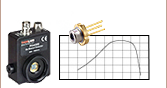
Standard Photodiode Sensors: S120C Series
| Item # | S120VC | S120C | S121C | S122Ca |
|---|---|---|---|---|
| Technical Specs | ||||
| Detector Type | Silicon Photodiode (UV Extended) | Silicon Photodiode | Silicon Photodiode | Germanium Photodide |
| Wavelength Range | 200 nm - 1100 nm | 400 nm - 1100 nm | 400 nm - 1100 nm | 700 nm - 1800 nm |
| Optical Power Range | 50 nW - 50 mW | 50 nW - 50 mW | 500 nW - 500 mW | 50 nW - 40 mW |
| Max Average Power Densityb | 20 W/cm² | 10 W/cm² | ||
| Max Pulse Energy | 20 µJ | |||
| Linearity | ±0.5% | |||
| Resolutionc | 1 nW | 1 nW | 10 nW | 2 nW |
| Measurement Uncertaintyd | ±3% (440 - 980 nm) ±5% (280 - 439 nm) ±7% (200 - 279 nm, 981 - 1100 nm) |
±3% (440 - 980 nm) ±5% (400 - 439 nm) ±7% (981 - 1100 nm) |
±3% (440 - 980 nm) ±5% (400 - 439 nm) ±7% (981 - 1100 nm) |
±5% |
| Responsivitye (Click for Details) |  Raw Data |
 Raw Data |
 Raw Data |
 Raw Data |
Compact Slim Photodiode Sensor
| Item # | S116C | ||
|---|---|---|---|
| Technical Specs | |||
| Detector Type | Silicon Photodiode | ||
| Wavelength Range | 400 - 1100 nm | ||
| Optical Power Working Range |
20 nW - 50 mW | ||
| Max Average Power Densitya |
20 W/cm² | ||
| Max Pulse Energy | 20 µJ | ||
| Linearity | ±0.5% | ||
| Resolutionb | 1 nW | ||
| Measurement Uncertaintyc |
±3% (451 - 1000 nm) ±5% (400 - 450 nm, 1001 - 1100 nm) |
||
| Responsivityd (Click for Details) |
 Raw Data |
||
Slim Profile Photodiode Sensors: S130C Series
| Item # | S130VC | S130C | S132Ca |
|---|---|---|---|
| Technical Specs | |||
| Detector Type | Silicon Photodiode (UV Extended) |
Silicon Photodiode | Germanium Photodide |
| Wavelength Range | 200 nm - 1100 nm | 400 nm - 1100 nm | 700 nm - 1800 nmb |
| Optical Power Range (with Filter) | 500 pW - 0.5 mWc (Up to 50 mW)c |
500 pW - 5 mW (Up to 500 mW) |
5 nW - 5 mW (Up to 500 mW) |
| Max Average Power Densityd |
20 W/cm² | 10 W/cm² | |
| Max Pulse Energy | 20 µJ | ||
| Linearity | ±0.5% | ||
| Resolution | 100 pWe | 100 pWe | 1 nWf |
| Measurement Uncertaintyg |
±3% (440 - 980 nm) ±5% (400 - 439 nm) ±7% (200 - 279 nm, 981 - 1100 nm) |
±3% (440 - 980 nm) ±5% (280 - 439 nm) ±7% (981 - 1100 nm) |
±5% |
| Responsivityh (Click for Details) | Raw Data |
Raw Data |
Raw Data |
Microscope Slide Photodiode Sensors
| Item # | S170C | S171C | NS170C |
|---|---|---|---|
| Technical Specs | |||
| Detector Type | Silicon Photodiode | Second-Order Nonlinear Crystal with Silicon Photodiode |
|
| Wavelength Range | 350 - 1100 nm | 400 - 1100 nm | Laser: 780 - 1300 nm SHG: 390 - 650 nm |
| Optical Power Working Range |
10 nW - 150 mW | 1 nW - 15 mW | Laser: 0.5 - 350 mWa SHG: 10 nW - 5 mW |
| Max Average Power Densityb |
20 W/cm2 | 10 W/cm2 | N/A |
| Max Peak Power Densityc | - | - | 10 TW/cm2 |
| Max Pulse Energy | - | - | - |
| Linearity | ±0.5% | ±0.5%d | |
| Resolution | 1 nWe | 0.5 pWf | 1 nWd,e |
| Measurement Uncertainty |
±3% (440 - 980 nm)g ±5% (350 - 439 nm)g ±7% (981 - 1100 nm)g |
±3% 440 – 980 nmg,h ±5% 400 – 439 nmg,h ±7% 981 – 1100 nmg,h |
±3% (440 - 650 nm)d,i ±5% (390 - 439 nm)d,i |
| Responsivityj (Click for Details) |
 Raw Data |
 Raw Data |
 Raw Data |
Integrating Sphere Photodiode Sensors
| Item # | S140C | S142C | S142CL | S144C | S145C | S145CL | S146C | S148C | S180C |
|---|---|---|---|---|---|---|---|---|---|
| Technical Specs | |||||||||
| Detector Type | Si Photodiode | Si Photodiode with Baffle | InGaAs Photodiode | InGaAs Photodiode with Baffle | InGaAs Photodiode | Extended InGaAs Photodiode | MCT (HgCdTe) Photodiode |
||
| Wavelength Range | 350 - 1100 nm | 400 - 1100 nm | 800 - 1700 nm | 900 - 1650 nm | 1200 - 2500 nm | 2.9 µm - 5.5 µm | |||
| Optical Power Range | 1 µW - 500 mW | 1 µW - 5 W | 10 µW - 5 W | 1 µW - 500 mW | 1 µW - 3 W | 10 µW - 3 W | 10 µW - 20 W | 1 µW - 1 W | 1 µW - 3 W |
| Max Average Power Densitya |
1 kW/cm² | 2 kW/cm² | 1 kW/cm² | 2 kW/cm² | 1 kW/cm² | ||||
| Max Pulse Energy Density |
1 J/cm² | 7 J/cm² | 1 J/cm² | 7 J/cm² | 1 J/cm² | ||||
| Linearity | ±0.5% | ||||||||
| Resolutionb | 1 nW | 10 nW | 1 nW | 10 nW | 1 nW | 10 nW | |||
| Measurement Uncertaintyc,d |
±3% (440 - 980 nm) ±5% (350 - 439 nm) ±7% (981 - 1100 nm) |
±3% (440 - 980 nm) ±5% (400 - 439 nm) ±7% (981 - 1100 nm) |
±5% | ||||||
| Responsivitye (Click for Plot) |
 Raw Data |
 Raw Data |
 Raw Data |
 Raw Data |
 Raw Data |
 Raw Data |
 Raw Data |
 Raw Data |
 Raw Data |
Fiber-Coupled Photodiode Sensors: S150C Series
| Item # | S150C | S151C | S154C | S155C |
|---|---|---|---|---|
| Technical Specs | ||||
| Detector Type | Si Photodiode | InGaAs Photodiode | ||
| Wavelength Range | 350 nm - 1100 nm | 400 nm - 1100 nm | 800 nm - 1700 nm | 800 nm - 1700 nm |
| Optical Power Range | 100 pW - 5 mW (-70 dBm to 7 dBm) |
1 nW - 20 mW (-60 dBm to 13 dBm) |
100 pW - 3 mW (-70 dBm to 5 dBm) |
1 nW - 20 mW (-60 dBm to 13 dBm) |
| Max Average Power Densitya | 100 mW/cm² | 10 W/cm² | 100 mW/cm² | 10 W/cm² |
| Max Pulse Energy | 20 µJ | |||
| Linearity | ±0.5% | |||
| Resolutionb | 10 pW (-80 dBm) | 100 pW (-70 dBm) | 10 pW (-80 dBm) | 100 pW (-70 dBm) |
| Measurement Uncertaintyc | ±3% (440 - 980 nm) ±5% (350 - 439 nm) ±7% (981 - 1100 nm) |
±3% (440 - 980 nm) ±5% (400 - 439 nm) ±7% (981 - 1100 nm) |
±5% | |
| Responsivityd (Click for Details) |  Raw Data |
 Raw Data |
 Raw Data |
 Raw Data |
センサーコネクタ
D型 オス
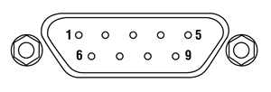
| Pin | Connection | ||
|---|---|---|---|
| S120, S140, and S150 Series, S116C, and S180C Sensors | S171 and S171C Sensors | S130 Series Sensors | |
| 1 | Not Used | ||
| 2 | EEPROM Data | ||
| 3 | Photodiode Anode and NTC Ground | Photodiode Anode Ground | Photodiode Anode |
| 4 | Photodiode Cathode | ||
| 5 | Not Used | ||
| 6 | EEPROM Ground | ||
| 7 | NTC | Not Used | Slider Detection |
| 8 | Not Used | ||
| 9 | Not Used | ||
パルスレーザ:パワーとエネルギーの計算

パルスレーザからの放射光が、使用するデバイスや用途に適合するかどうかを判断する上で、レーザの製造元から提供されていないパラメータを参照しなければならない場合があります。このような場合、一般には入手可能な情報から必要なパラメータを算出することが可能です。次のような場合を含めて、必要な結果を得るには、ピークパルスパワー、平均パワー、パルスエネルギ、その他の関連するパラメータを必要とすることがあります。
- 生物試料を損傷させないように保護する
- フォトディテクタなどのセンサにダメージを与えることなくパルスレーザ光を測定する
- 物質内で蛍光や非線形効果を得るために励起を行う
パルスレーザ光のパラメータは下の図1および表に示します。参照用として、計算式の一覧を以下に示します。資料を ダウンロードしていただくと、これらの計算式のほかに、パルスレーザ光の概要、異なるパラメータ間の関係性、および計算式の適用例がご覧いただけます。
計算式 | ||||
 | and |  | ||
 | ||||
 | ||||
 | ||||
平均パワーから算出するピークパワー、ピークパワーから算出する平均パワー : | ||||
 | and |  | ||
| 平均パワーおよびデューティーサイクルから算出するピークパワー*: | ||||
 | *デューティーサイクル( ) はレーザのパルス光が放射されている時間の割合です。 ) はレーザのパルス光が放射されている時間の割合です。 | |||
Click to Enlarge
図1: パルスレーザ光の特性を記述するためのパラメータを、上のグラフと下の表に示します。パルスエネルギ (E)は、パルス曲線の下側の黄色の領域の面積に対応します。このパルスエネルギは斜線で表された領域の面積とも一致します。
| パラメータ | シンボル | 単位 | 説明 | ||
|---|---|---|---|---|---|
| パルスエネルギ | E | ジュール[J] | レーザの1周期中に放射される1パルスの全放射エネルギ。 パルスエネルギはグラフの黄色の領域の面積に等しく、 これは斜線部分の面積とも一致します。 | ||
| 周期 | Δt | 秒 [s] | 1つのパルスの開始から次のパルスの開始までの時間 | ||
| 平均パワー | Pavg | ワット[W] | パルスとして放射されたエネルギが、1周期にわたって 均一に広がっていたと仮定したときの、 光パワーの大きさ(光パワー軸上の高さ) | ||
| 瞬時パワー | P | ワット[W] | 特定の時点における光パワー | ||
| ピークパワー | Ppeak | ワット [W] | レーザから出力される最大の瞬時パワー | ||
| パルス幅 |  | 秒 [s] | パルスの開始から終了までの時間。一般的にはパルス形状の 半値全幅(FWHM)を基準にしています。 パルス持続時間とも呼ばれます。 | ||
| 繰り返し周波数 | frep | ヘルツ [Hz] | パルス光が放射される頻度を周波数で表示した量。 周期とは逆数の関係です。 | ||
計算例
下記のパルスレーザ光を測定するのに、最大入力ピークパワーが75 mW
のディテクタを使用するのは安全かどうかを計算してみます。
- 平均パワー: 1 mW
- 繰り返し周波数: 85 MHz
- パルス幅: 10 fs
1パルスあたりのエネルギは、

と低いようですが、ピークパワーは、

となります。このピークパワーはディテクタの
最大入力ピークパワーよりも5桁ほど大きく、
従って、上記のパルスレーザ光を測定するのに
このディテクタを使用するのは安全ではありません。
当社では、幅広いパワーメータ&エネルギーメータ用コンソールやパワーセンサ・エネルギーセンサを操作するためのインターフェイスを取り揃えています。 主な仕様は下記でご覧いただけるので、お客様の用途に適したモデルをお選びいただけます。 下記のほかに、センサ内蔵のワイヤレスパワーメータや小型USBパワーメータもご用意しております。
当社のパワーメータ等用のコンソールやインターフェイスは、Cシリーズのセンサとお使いいただく場合は接続したセンサの種類を自動的に認識し、電流値とそれに応じた電圧値を測定します。 Cシリーズのセンサは、コネクタ内に感度特性の校正データが保存されています。 コンソールは、入射波長に対応する感度の値を読み出し、パワーもしくはエネルギの測定値を計算します。
- フォトダイオードセンサは、入射光の光パワーと波長によって決まる電流を流します。 この電流は、トランスインピーダンスアンプに送られ、このアンプから入力電流に比例した電圧が出力されます。 フォトダイオードの感度は波長に依存するため、正確なパワーの測定値を得るためには、コンソールに正しい波長を入力する必要があります。 コンソールは、接続されたセンサから、入力された波長における感度を読み取り、測定した光電流から光パワーを計算します。
- サーマルセンサは、入射された光パワーに比例した電圧を送ります。 測定されたセンサの出力電圧とその感度特性に基づいて、コンソールは入射した光パワーを計算します。
- エネルギーセンサは焦電効果に基づいています。 したがって、エネルギーセンサは、パルスエネルギに比例したピーク電圧を送ります。 エネルギーセンサが認識されると、コンソールはピーク電圧ディテクタを活用し、センサの感度特性からパルスエネルギが計算されます。
コンソールやインターフェイスはセンサが出力する電流や電圧を表示する機能も備えています。 または、測定された電流や電圧をアナログ出力で得ることもできます。
コンソール
| Item # | PM100A | PM100D | PM400 | PM5020 |
|---|---|---|---|---|
| (Click Photo to Enlarge) | 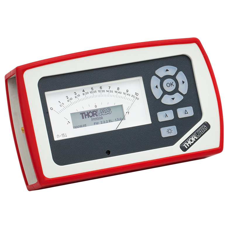 | 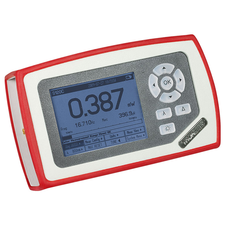 | 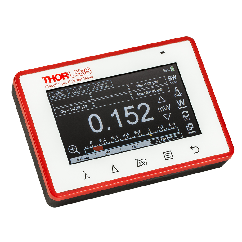 | 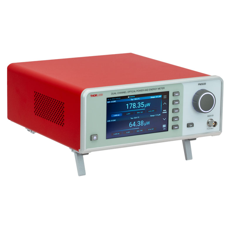 |
| Key Features | Analog Power Measurements | Digital Power and Energy Measurements | Digital Power and Energy Measurements, Touchscreen Control | Dual Channel |
| Compatible Sensors | Photodiode and Thermal Power | Photodiode Power, Thermal Power, and Pyroelectric Energya | Photodiode Power, Thermal Power, Thermal Power and Position, and Pyroelectric Energya | Photodiode Power, Thermal Power, Thermal Power and Position, and Pyroelectric Energy |
| Housing Dimensions (H x W x D) | 7.24" x 4.29" x 1.61" (184 mm x 109 mm x 41 mm) | 7.09" x 4.13" x 1.50" (180 mm x 105 mm x 38 mm) | 5.35" x 3.78" x 1.16" (136.0 mm x 96.0 mm x 29.5 mm) | 9.97" x 4.35" x 11.56" (253.2 mm x 110.6 mm x 293.6 mm) |
| Channels | 1 | 2 | ||
| External Temperature Sensor Input (Sensor not Included) | - | - | Readout and Record Temperature Over Time | Readout and Record Temperature Over Time |
| External Humidity Sensor Input (Sensor not Included) | - | - | Readout and Record Humidity Over Time | Readout and Record Humidity Over Time |
| Input/Output Ports | - | 4 GPIO, Programmable | 4 Configurable Digital I/O Channels | |
| Shutter Control | - | - | - | Support for SH05R(/M) or SH1(/M) Optical Shutter with Interlock Input |
| Fan Control | - | - | - | |
| Source Spectral Correction | - | - | ||
| Attenuation Correction | - | - | ||
| External Trigger Input | - | - | - | |
| Display | ||||
| Type | Mechanical Needle and LCD Display with Digital Readout | 320 x 240 Pixel Backlit Graphical LCD Display | Protected Capacitive Touchscreen with Color Display | |
| Dimensions | Digital: 1.9" x 0.5" (48.2 mm x 13.2 mm) Analog: 3.54" x 1.65" (90.0 mm x 42.0 mm) | 3.17" x 2.36" (81.4 mm x 61.0 mm) | 3.7" x 2.1" (95 mm x 54 mm) | 4.32" x 2.43" (109.7 mm x 61.6 mm) |
| Refresh Rate | 20 Hz | 10 Hz (Numerical) 25 Hz (Analog Simulation) | 25 Hz | |
| Measurement Viewsb | ||||
| Numerical | ||||
| Mechanical Analog Needle | - | - | - | |
| Simulated Analog Needle | - | |||
| Bar Graph | - | |||
| Trend Graph | - | |||
| Histogram | - | - | - | |
| Statistics | ||||
| Memory | ||||
| Type | - | SD Card | NAND Flash | SD Card |
| Size | - | 2 GB | 4 GB | 8 GB |
| Power | ||||
| Battery | LiPo 3.7 V 1300 mAh | LiPo 3.7 V 2600 mAh | - | |
| External | 5 VDC via USB or Included AC Adapter | 5 VDC via USB | Line Voltage: 100 - 240 V | |


| Posted Comments: | |
Seongjae Lee
(posted 2024-02-13 16:51:03.627) Dear Thorlabs,
Recently, I purchased S122C through BM Laser solution in South Korea.
I connected S122C to PM101 and measured output from 905 nm pulsed LD.
However, we found that the output value changes significantly by measuring setting especially "Attenuation" "Range"
Also, it shows very different value with S405C which we purchased previously.
I'm not sure with setting of S122C guarantees reliable average power of the input light.
The pulsed duration, repetition rate, average power of the 905 nm pulsed LD output is 100 ns, 1 kHz, and 12.5 mW.
Can you tell me how to set up the S122C and how to measure the reliable optical power? hkarpenko
(posted 2024-02-14 11:50:49.0) Dear customer,
thank you very much for your feedback. Measuring pulsed laser sources with photodiode sensors can be challenging depending on the laser parameters. Especially the peak power of the laser can damage the sensor or the repetition rate is too low, thus the sensor is fast enough to follow some pulses. I will contact you directly to discuss this further with you. 諒一 芝山
(posted 2023-11-01 11:35:58.37) 同製品の再校正を検討しております。
メーカーでの校正を依頼させて頂く場合、校正依頼書等の文書作成は必要でしょうか?
(*オフィール社では修理・構成作業依頼書の送付が必要であったため) fmortaheb
(posted 2023-11-02 05:03:03.0) Thank you very much for contacting us. An application engineer from our team in Japan will discuss this directly with you. Marie Zandi
(posted 2023-08-24 16:07:02.443) Hi,
I would like to measure the average power of a ns pulsed laser (fiber coupled). I have access to the S145C integrating sphere and would like to know if I can use it for this. I saw some of your posted comments on this feedback page, and it looks like a thermal sensor might be better for an accurate power measurements. The pulsed laser specs are: 30ns in pulse length, repetition rate of 10kHz, average power of 100mW, peak power of 330W. Could you help me with this? Thank you. dpossin
(posted 2023-08-28 09:14:49.0) Dear Marie,
Thank you for your feedback. Your intendet application does not work with photodiodes for two reasons:
The peak pulse power will saturate the photodiode
The duty cycle is way too low in order to perform average power measurement
Your are right by suggesting that a thermal sensor will be a much better choice.
I reach out to you in order to provide more detailed information. user
(posted 2023-08-24 16:05:59.117) Hi,
I would like to measure the average power of a ns pulsed laser (fiber coupled). I have access to the S145C integrating sphere and would like to know if I can use it for this. I saw some of your posted comments on this feedback page, and it looks like a thermal sensor might be better for an accurate power measurements. The pulsed laser specs are: 30ns in pulse length, repetition rate of 10kHz, average power of 100mW, peak power of 330W. Could you help me with this? Thank you. Miao Zhu
(posted 2023-08-08 18:19:58.593) Hello,
It seems the power meter PM100D does not display the the correct power when using S112C (or S145C). We tried on two different PM100D units. Is there a power meter which can read S112C and S145C?
Thank you. hchow
(posted 2023-08-10 09:26:08.0) Dear Miao Zhu, thank you for your feedback. I will personally reach out to you to provide assistance. Thank you. 申 钰铜
(posted 2023-07-26 10:12:35.253) 你好,我的s130c的滤光片损坏了,请问可以更换配件么?麻烦提供一下型号 hchow
(posted 2023-07-27 03:44:46.0) 我们可以为您的S130C更换过滤器,但是,您必须联系我们的Thorlabs中国公司进行RMA。 sanghyun Choi
(posted 2023-06-29 20:02:37.613) I have PM200 meter.
Is this sensor compatible with PM200 meter?
Best regards
Sanghyun wskopalik
(posted 2023-06-30 09:36:55.0) Thank you very much for your feedback!
Yes, the PM200 is compatible with the S122C.
I will contact you directly to provide further assistance. user
(posted 2023-04-17 21:45:16.387) What is the maximum peak pulse power for the S120C photodiode sensor? I'm asking becuase the specs contain only information about the max. average power density and the max. pulse energy. hchow
(posted 2023-04-18 06:39:18.0) Dear User, thank you for your feedback. So long as your peak pulse power doesn't exceed the maximum average power density, 20 W/cm², or the maximum pulse energy, 20 µJ, your laser should be fine to use.
For continuous wave (CW) sources, the maximum average power density is equivalent to the peak power density, while for pulsed laser sources this value is calculated from the time-averaged power and beam profile. The maximum average power density is determined by the total energy deposited, so the instantaneous power can be higher, as long as the maximum pulse energy is not exceeded. Junyu Li
(posted 2023-01-05 16:47:23.097) I bought an S140C probe with serial number 220601140, and the number of valid digits of the responsitivity data on the included test report is only 3 digits, is there any way to get the 4-digit significant digit data? (Is it okay to use the PM400) Because the responsitivity curve attached to your website has four significant digits. hchow
(posted 2023-01-05 05:07:49.0) Dear Mr. Li, thank you for your feedback. I will personally reach out to you to provide the necessary information you seek. Thank you. Vincent Mazoyer
(posted 2022-11-08 14:40:08.72) Dear Sir or Madam,
The CAD model is wrong: the mounting holes are too close to the sensing area in the model; do not match the drawings. Also, the model shows S130C instead of S130VC; filename says S130VC nevertheless.
Sincerely yours,
Vincent Mazoyer hchow
(posted 2022-11-09 03:20:06.0) Dear Mr. Mazoyer, thank you for your feedback. I will personally reach out to you to discuss this matter. Thank you very much. D M
(posted 2022-10-11 12:46:45.26) Hello, is it possible to provide a photodiode power sensor for wavelengths between 1900nm and 2000nm? hchow
(posted 2022-10-11 11:04:14.0) Hi, thank you very much for your enquiry. We do indeed have a photodiode power sensor capable of detecting between 1900 nm to 2000 nm and it is our S148C. The S148C is efficient in detecting light between 1200 nm to 2500 nm. I will personally reach out to you to provide more information about the specifications of this photodiode power sensor. Thanks again. Alan Lin
(posted 2022-09-27 19:21:39.45) Hi,
Good day,
Do you have any material about power measure response on different incident angle for pm160-121 detector?
thanks, wskopalik
(posted 2022-09-28 03:11:34.0) Thank you very much for your feedback!
We make the calibration of these sensors with a beam which is incident on the sensor perpendicularly. So for best accuracy it is recommended to use these sensors at an angle of incidence which is as close to perpendicular as possible. For other angles, deviations of a couple of percent in the power readings are possible.
I will contact you directly to provide further information. Juan de Dios Marin de Espinosa Romero
(posted 2022-09-26 06:39:05.833) good morning, my name es Juan Marin , Manager of labortecnic S.A. company from Granada Spain ,
Dedicate to distribution instrument scientific for Center for investigation, I need ofert of your reference ;
S121C - Sensor de potencia de fotodiodo estándar, Si, 400 - 1100 nm, 500 mW with transport to Granada Spain
dates for facturarion
labortecnic S.A.
c/ fray Luis de Leon, 3, 18004 Granada
CIF A18512582
TFNO 958294402
jmarin@labortrecnic.es H K
(posted 2022-09-19 15:44:22.1) Hello. I would like to ask a question power range of S120C.
In the given specsheet, the lower boundary of power range is 50 nW.
In my experience, it seems that power of less than 50 nW can be measured under the experimental conditions with good sealing.
Can you explain what the 50 nW value means? wskopalik
(posted 2022-09-19 04:30:58.0) Thank you very much for your feedback!
The lower limit of the power range is mainly determined by dark current in the photodiode and noise in the electronics. The 50 nW are what we can safely specify for this sensor type. It is however not a hard limit. Depending on the batch of the photodiode and on the measurement settings, you might also be able to measure power levels a little below 50 nW.
I will contact you directly to provide further assistance. A. T.
(posted 2022-07-25 08:03:38.09) Hi, I would like to measure a 40W (max) signal @1000nm. Note that it is a 50ms pulse, not CW, and we would use the PM103A power meter.
Would it be possible to use a S146C integrating sphere at this power and this wavelength?
I assume that the 20W limit of the sphere is the non-linearity of the sensor above 20W. Considering that the sensor is mush less responsive @1000nm, it would therefore be possible to go up to 40W.
Thank you. dpossin
(posted 2022-07-26 10:49:11.0) Dear Antonin,
Thank you for your inquiry. We do not specify our powermeters beyond the specified powerrange. Please also note that integrating sphere based sensors are not very well suited for pulsed lasers as the sphere broadens the pulse. At 40W most probably the sensor will saturate or even gets damaged at a power level of 40W. I am reaching out to you in order to discuss this in more detail. user
(posted 2022-07-11 08:06:09.287) Hi, using the S145C integrating sphere. In addition to my last question, what is the max. incident angle of a beam in the sphere aperture? dpossin
(posted 2022-07-13 05:58:49.0) Dear Customer,
Thank you for your feedback. This is an response to both of your questions. First of all the linearity is the relative measurement accuracy based on the resolution the photocurrent can be measured by the powermeter console. The measurement uncertainty in contrast is the absolute measurement accuracy based on the tolerance on the reference photodiode and the uncertainty in the calibration setup. user
(posted 2022-07-11 06:13:30.46) Hi, using the S145C integrating sphere.
What do you mean by linearity of +- 0,5 % and a measurement uncertainty of +- 5 %. Can you explain further?
thank you in advance. Eric Lentz
(posted 2022-06-06 10:50:16.94) Hello. It would be great if there was an adaptor to the S142C power sensor with the threaded plate still on. We are switching between the S120-FC and the S140-BFA so we leave the threaded plate on the power sensor and made a rough adaptor for the S140-BFA to the threaded plate. Thanks dpossin
(posted 2022-06-08 05:48:34.0) Dear Eric,
Thank you for your feedback. I am reaching out to you in order to discuss possible options. Zhenpu Zhang
(posted 2022-05-10 02:26:07.603) Hi, I am wondering what the communication protocol between the sensor head and the console is for transmitting the EEPROM Data?
Is it through UART? dpossin
(posted 2022-05-10 09:34:54.0) Dear Zhenpu,
Thank you for your inquiry. We are using 1-wire to communicate between the EEPROM and our powermeter consoles. user
(posted 2022-03-08 16:11:04.957) When using the S120C at 1064 nm, the unit will report much higher power than the 50 mW engraved on the back. This doesn't seem unreasonable as the QE is so different from the maximum QE value (at a different wavelength).
However, is the response nonlinear at these intensities for this wavelength?
Thanks for your time! soswald
(posted 2022-03-14 06:50:55.0) Dear David,
thank you for your feedback. I have reached out to you directly to discuss your measurements in more detail. Siva Natrajan
(posted 2021-07-20 21:22:24.053) I have an S155C detector. I would like to know the Integration time & bandwidth of this detector MKiess
(posted 2021-07-26 05:06:18.0) Dear Siva, thank you very much for your inquiry. The S155C is an InGaAs photodiode, integrated into a C-Type connector Design, compatible with our power meter consoles. The photodiode only generates a current proportional to the light power reaching the active sensor area. The integration time is therefore given by the measurement console. The rise time of the diode itself is in the nanosecond range. I have contacted you directly to discuss further details in combination with your measurement console. tseng yaohsin
(posted 2021-06-17 17:16:01.31) Hi Thorlabs,
Could you share the raw data of the responsibility for this detector to me ?
The csv or excel should be fine.
Thanks. cdolbashian
(posted 2021-06-22 05:09:37.0) Thank you for reaching out to us at Thorlabs! All of our raw data can be found on the product family page in close proximity to the individual product listing: in this case on the table where the S148C specs are listed. I have contacted you directly with the data you requested, and the specific method of locating it on the web page. Atefeh Ajami
(posted 2021-06-16 20:21:13.847) I want to calculate the uncertainty of the power meter
I wanted to know how? And what quantities are effective in this uncertainty? soswald
(posted 2021-06-18 09:49:46.0) Dear Atefeh,
thank you for your feedback. The measurement uncertainty of the S120VC is wavelength dependent:
±3% (440 - 980 nm)
±5% (280 - 439 nm)
±7% (200 - 279 nm, 981 - 1100 nm)
This uncertainty takes several uncertainties of our calibration setup into account such as reference diode uncertainty, wavelength set and bandpass uncertainty, temperature uncertainty and uncertainties of the electric circuit used to measure the photocurrent during calibration. Chang Jeremy
(posted 2020-11-06 00:31:58.187) Hello
I want to understand how to calculate the standard deviation in the power meter. I did a program to control PM100D and I calculated standard deviation by calculating mean power with common method on Wiki;however, the value I calculate is 10 times than the value Power meter showed. Please give a hand. Thanks!
Best, Jeremy dpossin
(posted 2020-11-10 10:47:13.0) Dear Jeremy,
Thank you for your feedback. The standard deviation is calculated on the fly. I am reaching out to you in order to provide the relevant algorithm we use to calculate the standard deviation. user
(posted 2020-10-17 10:14:25.98) I have a photodiode S132C, I measure the photocurrent by transimpedance amplifier and next lock-in at 0V bias. I need to determine the power density of the light out from the monochromator. What area do I need to take to right calculate power density, the active detector area, or beam size? MKiess
(posted 2020-10-19 10:38:08.0) Thank you very much for your inquiry. To measure the power density, you should use the beam size incident on the sensor. pao chen
(posted 2020-09-14 13:37:16.15) I have 2 units of S120VC working with 2 PM100D meters.
However, I leant that the reading of S120VC is about 55%~ 60% of that measured by various SiC sensors at 265nm and 275nm.
It is significant to determine which reading is correct in UV measurement. Can you please provie your opinion on this matter? MKiess
(posted 2020-09-15 04:55:14.0) Thank you very much fo your inquiry. If the sensor is currently calibrated and the wavelength and power range settings on the Power Meter are correct, the S120VC should have a maximum measurement uncertainty of ±7% in this wavelength range.
I have contacted you directly to discuss your measurement results in detail. Michal Pelach
(posted 2020-07-09 08:41:26.2) Is it possible to get sensor calibration data at 785 nm? MKiess
(posted 2020-07-10 08:29:39.0) This is a response from Michael at Thorlabs. Each S120VC is individually calibrated before delivery. Therefore the values are slightly different for each sensor. The typical value for the responsivity of the S120VC at 785nm is 35.69mA/W. I have contacted you directly to discuss the exact details for your sensor. li bo
(posted 2020-06-16 21:01:29.83) 积分球传感器里面脏了,怎么清理呢 wskopalik
(posted 2020-06-17 10:26:09.0) This is a response from Wolfgang at Thorlabs. Thank you very much for your inquiry.
The question is how integrating sphere sensors like the S142C can be cleaned. The housing may be cleaned by wiping with a soft damp cloth. The integrating sphere inner surface however cannot be cleaned and should not be touched. You can gently blow off any debris using compressed air. If this does not remove all the dirt or dust in the sphere, the sphere will probably need to be exchanged so you would need to send the sensor in for a repair.
Our Tech Support team in China will reach out to you directly. 達也 真藤
(posted 2020-04-16 21:52:55.94) 積分球パワーセンサS146Cについて、スペックシートにMax Pulse Energy Density 7 J/cm²との記載があったが、これはレーザの1周期中に放射される1パルスの全放射エネルギーを意味している、という解釈で良いか確認させて頂きたい。 MKiess
(posted 2020-04-20 05:26:42.0) お問合せをありがとうございました。ソーラボジャパンの技術サポートから直接回答をいたします。 xinxin peng
(posted 2020-04-10 16:55:13.01) 应用太有限,我们希望底部有个M4的螺孔,用支柱用于各种光路系统中,希望采纳。 YLohia
(posted 2020-04-10 09:40:01.0) Thank you for contacting Thorlabs. An applications engineer from our Tech Support team in China will reach out to you directly. user
(posted 2020-02-25 10:34:47.983) Hi,
I'm using the S130C to measure the power of a beam, either collimated, divergent or focused. Is it normal to have different power values depending on whether the beam covers a large fraction of the detector's surface (case of collimated beam) or covers a small surface (focused beam)?
Thank you for your help
Best nreusch
(posted 2020-02-27 09:02:08.0) This is a response from Nicola at Thorlabs. Thank you very much for your feedback! S130C comes with a Si photodiode. Photodiodes in general are sensitive to the angle of incidence. So for focused and divergent beams, you will always have parts of the beam that will not hit the sensor at a right angle, which will affect the measurement. Photodiode sensors will also not show a completely uniform response over their active area. Therefore, the specified measurement uncertainty is only valid for beam diameters larger than 1 mm. You should also take care to not overfill the sensor with a divergent beam. We will contact you directly to discuss your specific application in more detail. Matthew Kirchner
(posted 2019-11-25 13:24:07.727) Hi, does the S142C correct for temperature dependence of the Si photodiode responsivity? dpossin
(posted 2019-11-27 08:43:20.0) Dear Customer,
Thank you for your feedback. The S142C does not compensate temperature effects of the sensor automatically. However it is possible to compensate
the temperature dependent dark current with our powermeter consoles. I am reaching out to you to provide further information on that. user
(posted 2019-11-15 12:57:48.94) Dear Thorlabs,
We are considering ordering one of your products to measure the average power of a scanned pulsed laser, that reaches an aperture of a few mm, with the following parameters:
» Beam width: 1 mm
» Wavelength: 1,5 micron
» Pulse energy: 1 micro-Joule
» Pulse duration: 1 nW
The pulse train incident on the opening depends on its diameter as well as the scanning parameters:
» Repetition frequency: minimum 10 Hz (frame rate); maximum 1MHz (pulse repetition rate)
» Average power on aperture: typical 10 mW; minimum 10 micro-W; maximum 1 W (static beam).
Which kind of power meter do you recommend for the described application: a photo-diode/integrating sphere or a thermopile?
Sincerely,
Flávio Ferreira
-----
University of Minho
Department of Physics MKiess
(posted 2019-11-18 06:12:44.0) This is a response from Michael at Thorlabs. Thank you for the inquiry. Depending on the pulse duration, repetition rate, laser power and the general conditions of your application, a thermal sensor or a photodiode sensor may be suitable for you. In order to be able to use this optimally, different conditions have to be fulfilled depending on the sensor type. Details can be found under the following link:
https://www.thorlabs.de/newgrouppage9.cfm?objectgroup_id=6188&tabname=%20Sensor%20Selection
I contacted you directly to discuss further details and select the most suitable sensor together with you. Karim Elkhouly
(posted 2019-10-23 07:39:14.07) I am considering using an integrated sphere for calibrated EQE measurements of LEDs. I am wondering what is the fundamental difference between standard power meters like the S120VC and ones for integrating spheres. Especially that the minimum detectable power is much higher in the latter option. Can I use S120VC with integrating sphere for example ? MKiess
(posted 2019-10-28 11:09:54.0) This is a response from Michael at Thorlabs. Thank you for the inquiry. The radiation scattered in the integrating sphere is almost ideally diffuse over the specified spectrum. This allows on the one hand to measure a photometric standard and on the other hand to measure the power or the total radiation flux of different light sources, independent of beam uniformity, divergence, beam shape and entrance angle, making them excellent for use with fiber sources and off-axis free space sources.
Due to the diffusivity, the power range is also higher than that of the sensors with which the radiation is measured directly, such as the S120VC.
These are therefore better suited for measurements of collimated beams with small powers.
I have contacted you directly to select the most suitable sensor for your application together. Andrey Kuznetsov
(posted 2019-07-12 15:15:12.757) S12X series photodiodes have a poorly modeled solidworks file, can you update the model to reflect the internal size and position of the photodiode. While the aperture is 9.5mm, the aperture appears to be 3.3mm from the photodiode based on PDF drawing. This means that when measuring divergent light, if the photodiode is not large enough to collect all the light passing through the 9.5mm aperture then the measurement will be wrong. A +-45 degree light passing through a 9.5mm aperture with detector at 3.3mm away from aperture will expand the minimum radius of the photodiode by 3.3mm to 16.1mm diameter. wskopalik
(posted 2019-07-23 10:33:46.0) This is a response from Wolfgang at Thorlabs. Thank you very much for your inquiry!
It is generally not recommended to measure strongly divergent beams with a S12X series sensor. One reason is - as you have mentioned - that it is difficult to make sure that all the light is collected by the photodiode. In addition, photodiodes also show a dependence of the responsivity with respect to the angle of incidence. So these sensors are not ideal.
For a divergent beam e.g. the sensors of the S14X series would be much more suitable. These have an integrating sphere which makes the collection of the light easier and which also ensures that the light is shining on the photodiode perpendicularly.
I will contact you directly regarding these sensors and the drawings. Andrey Kuznetsov
(posted 2019-07-09 11:39:03.727) Please update the Drawing for S122C, it points to a PDF that includes other photodiodes and does not explicitly mention S122C anywhere. mmcclure
(posted 2019-07-11 08:16:35.0) Hello, thank you for bringing this to our attention. We have added the S122C-specific PDF drawing on the webpage. user
(posted 2019-07-03 19:19:41.117) Can Thorlabs improve the calibration uncertainty from 3% to 1%? This is the major sticking point when considering Thorlabs photodiodes for use in precise calibration systems where 0.5% errors matter. dpossin
(posted 2019-07-05 10:34:27.0) Dear customer,
Thank you for your feedback. Unfortunately we can not specify an uncertainty of 1% over the full spectral range. Our references are calibrated by PTB or NIST and have an uncertainty of 0.3% up to 1.5% with respect to the wavelength. If we take into account the expanded uncertainty trough the reference and the calibration Setup, we get an Overall uncertainty of 2% for silica based sensors and 3% for germanium based sensors. user
(posted 2019-06-19 11:51:29.203) Could you use the same ND filter that you used for the S121C Silicon head so as to allow this Ge head to measure up to 500mW?
We could really use a Ge head that measures up to 500 mW. wskopalik
(posted 2019-06-21 09:57:17.0) This is a response from Wolfgang at Thorlabs. Thank you very much for your inquiry!
We should be able to offer this as a custom version. I will contact you directly regarding your requirements. Alternatively, you could also use the S132C which has a Ge photodiode and can measure up to 500mW or also the S144C which has an InGaAs photodiode. On the S144C the wavelength range is slightly different, but you can also measure up to 500mW. user
(posted 2019-05-01 13:02:36.09) The strain relief for the cable exiting the 9 way D connector head-shell is inadequate. From active use in the lab, the flexing has broken the outer sheath and is putting strain onto the inner conductors. I have had to effect an interim repair - can send you pics if you contact me. wskopalik
(posted 2019-05-02 07:47:21.0) This is a response from Wolfgang at Thorlabs. Thank you very much for your feedback!
I'm sorry to hear about this issue with your sensor. I will contact you directly so you can send me pictures of the defective cable. I'm sure that we will find a good solution in this case. Fabian Röser
(posted 2019-04-09 04:02:07.897) Dear Sir/Madam,
when measuring the average power of a pulsed system with a S145C integrating sphere, I noticed that the response is strongly dependend on the actual repetition rate of the pulse train. Measuring at 50kHz shows only a fraction of the average power.
Could you please specify the repetition frequency band of quasi-cw signals in which these Sensors can be used? Also, can they be modified to work with repetion rates in the kHz range?
Thanks in advance nreusch
(posted 2019-04-16 06:16:03.0) This is a response from Nicola at Thorlabs. Thank you for your inquiry. The behavior that you observed results from the combination of the rise and fall times of the photodiode as well as the electronic bandwidths of amplifiers and converters of the readout circuits. I recommend using a thermal power head in order to measure the average power of a pulsed system. I will contact you directly to discuss different options for your application. yongqi.shi
(posted 2019-01-30 09:26:44.323) Dear Sir/Madam, I'm using S130C power sensor. When I use the filter to measure the optical power around 28mW, I found that the there's always a 15% to 20% deviation when change the incident angle of the beam from -20 deg to 20 deg. What would be the reason and how to get a more precise measurement? Thank you in advance. wskopalik
(posted 2019-02-04 10:51:28.0) This is a response from Wolfgang at Thorlabs. Thank you very much for your inquiry!
The ideal case for photodiode sensors is if the beam hits the photodiode and the filter perpendicularly. This is how the sensors are calibrated so the accuracy is the highest in this case. The responsivity of photodiodes as well as the attenuation of filters depend on the angle of incidence. This means that the displayed power readings will change if the angle of incidence is changed. Thermal power sensors are more suitable for applications in which the angle changes because they have much less dependence on the angle of incidence.
I will contact you directly to provide further assistance. user
(posted 2019-01-23 13:11:44.777) Dear Sir. Is it possible to use two Powermeter S121 at the same time with the same software on PC?Now I only can choose one USB-connection at the software. wskopalik
(posted 2019-04-05 11:02:09.0) This is a response from Wolfgang at Thorlabs. Thank you very much for your feedback!
Yes, it is possible to operate up to eight power meters simultaneously in the power meter software. You would need a power meter for each sensor which you want to operate in the software. Maybe there is an issue with one of these connections. It is however hard to tell without further details.
Unfortunately, you didn't leave any contact details in the feedback so I cannot contact you directly. Please feel free to contact me any time at europe@thorlabs.com. abc124771
(posted 2019-01-21 17:01:19.24) What does 'max. avg. power density' of 20W/cm2 signify? Does it mean it can withstand 20W? Or is the max. power it can withstand given by the range which is 500mW for S130C? swick
(posted 2019-01-25 04:11:07.0) This is a response from Sebastian at Thorlabs. Thank you for the inquiry. The max. average power density represents the damage threshold of the sensor. dietrich
(posted 2018-12-13 10:50:27.293) Dear, Sir. We want to measure light which is more or less broadband with a wavelength of 1900 to 2300 nm in the power range from 1 mW to 1 W. Unfortunaly your detector S148C has in this area strong nonlinearities. Is it possible that you replace the build in photo diode with a different one like extended InGaAs with a cutoff wavelength of 2.6 μm?
With best Regards Christian Markus Dietrich nreusch
(posted 2018-12-19 02:22:17.0) This is a response from Nicola at Thorlabs. Thank you very much for your inquiry. Yes, we can offer customized versions of our integration spheres with different diodes. I will contact you directly to discuss further details. aSadykov
(posted 2018-07-17 09:55:31.477) Dear, Sir.
Datasheet for S122C include parameter -"Measurement Uncertainty" which is equal to "+/- 5%".
and collibration has been made in accordiance with NIST.
I'd like to make clear "Measuremet Uncertainty" in data sheet is "Standard measurement uncertainty" or something else.
https://www.nist.gov/itl/sed/topic-areas/measurement-uncertainty
With best Reguards
Andrey Sadykov nreusch
(posted 2018-07-20 10:17:17.0) This is a response from Nicola at Thorlabs. Thank you for your inquiry! Your assumption is correct. The "Measurement Uncertainty" specification corresponds to the "Standard Measurement Uncertainty" as defined by NIST. jhamilton
(posted 2018-05-30 13:19:00.957) Can you please provide me with operational temperature range for the S122. Can you also provide me with RoHS status.
Thank you mvonsivers
(posted 2018-06-05 05:15:09.0) This is a response from Moritz at Thorlabs. Thank you for your inquiry. The RoHS declaration can be found by clicking on the red document button next to the product number. The sensors are calibrated at room temperature, operating them at other temperatures will reduce the accuracy of the measurement. cyprien.lanthermann
(posted 2018-04-19 16:09:31.14) Hi, could you tell me the accuracy on the diameter of the photodiode?
Thanks,
Lanthermann Cyprien swick
(posted 2018-04-27 04:16:20.0) This is a response from Sebastian at Thorlabs. Thank you for the inquiry. The Photodiode used in S132C has an active area of 9.7 mm x 9.7 mm and the clear aperture is 9.5 mm (+/- 0.02 mm). user
(posted 2018-01-15 09:28:55.797) Hi, is the sensor head is well shielded against ESD? or should the user be grounded while connecting it to the console?
Thanks, mvonsivers
(posted 2018-01-16 08:19:12.0) This is a response from Moritz at Thorlabs. Thank you for your inquiry.
As the photodiode is mounted inside the sensor housing it is generally not as ESD sensitive as a bare photodiode. Nevertheless, the user must use handling procedures that prevent any electro static discharges or other voltage surges when handling or using these devices. mailfert
(posted 2017-11-17 13:28:07.937) Hi,
The glass window in front of my detector is broken, not the sensor.
This window is removable so I'm trying to know if we can just buy the window without the complete sensor.Best regards. wskopalik
(posted 2017-11-22 04:41:47.0) This is a response from Wolfgang at Thorlabs. Thank you very much for your inquiry!
We don't recommend to exchange the ND filter window on these sensors yourself because the calibration is only valid with the filter which was mounted during the calibration. There are slight differences from filter to filter. So if the filter needs to be exchanged, the sensor needs to be recalibrated after the exchange. This can only be done in our facilities.
I will contact you directly to discuss the further proceedings. lebouquj
(posted 2017-10-11 16:47:30.52) Hi, I am interested by detection in 1200-2500nm spectral range, with minimum flux 10nW. This spectral range is only made available in Integrating-Sphere design (S148C), thus is poorly sensitive (1uW). Would it be possible to have the sensor of S148C but packaged as the S132C (which has 5nW resolution) ? Thanks wskopalik
(posted 2017-10-16 05:06:35.0) This is a response from Wolfgang at Thorlabs. Thank you very much for your inquiry!
The photodiode used in the S148C which can cover this spectral range only has an active area of 1 mm in diameter. So with our sensor designs this photodiode only works in an integrating sphere. E.g. for the S132C design, the active area would need to be 9.7 mm x 9.7 mm in size.
Our R&D is looking into the possibility of offering a special sensor for your requirements and I will contact you directly about this. storm.liao
(posted 2017-09-15 09:57:27.58) Would you please let me know the active area of S122C? tcampbell
(posted 2017-09-15 11:18:45.0) Hello, thank you for contacting Thorlabs. The active detector area of the S122C is 9.7 mm x 9.7 mm. This value can be found on the spec sheet, but we will try to make it more visible on the website. jv
(posted 2017-09-02 08:43:39.217) It would be great to have an adapter that allows the power detector to measure the output from an FC bulkhead (female). So the adapter would have a hole that fits over the threads of the bulkhead to measure power output. We use this ALL THE TIME for calibrating our products. Could also extend the idea to other bulkhead connectors. Thanks, Janis mvonsivers
(posted 2017-09-04 04:24:17.0) This is a response from Moritz at Thorlabs. Thank you for your feedback. I agree that such an adapter would be useful and I will gladly forward your suggestion to our R&D department. At the moment you can still measure the output by using a short patch cable which can be connected to the power sensor via an S120-FC adapter. ycandela
(posted 2017-07-26 12:48:54.997) I would like to use it from -40°C to 63°C.What is the operating temperature range of the integrating sphere S142C ? Tx wskopalik
(posted 2017-07-27 10:06:08.0) This is a response from Wolfgang at Thorlabs. Thank you very much for your inquiry.
The sensor itself wouldn't be damaged in this temperature range. There are however two drawbacks regarding the measurement accuracy.
First, you would need to make sure that there is no condensation inside the integrating sphere of the S142C due to the temperature change. Condensation would change the reflectivity of the sphere surface and would therefore affect the measurement values.
Second, the responsivity of Silicon photodiodes is dependent on the temperature. The calibration of these sensors is made at room temperature so you will get the most accurate reading there. In your case the temperature changes over 100K which would certainly affect the accuracy. This effect is more pronounced from 1000nm to higher wavelengths.
I will contact you directly to provide further assistance. andrey.kuznetsov
(posted 2017-04-11 21:43:48.073) Do you have photodiodes that have 1% uncertainty error on calibration at 940nm? Newport offers several at this calibration error, but Thorlabs only seems to have 3% or more.
Do you have a typical non-uniformity map of the 10x10mm photodiode sensors? I'd like to see how a small beam spot would be affected by non-uniformity. yes, I know you recommend at least 10% and others say calibration is done at 70% fill, I want a map to see for myself the non-uniformity. wskopalik
(posted 2017-04-12 03:48:25.0) This is a response from Wolfgang at Thorlabs. Thank you very much for your inquiry.
We might be able to offer photodiodes with calibration uncertainties below 3%. We also have data about the non-uniformity of the responsivity of these photodiode sensors which I will send to you. The non-uniformity of the photodiode itself is about +/- 0.5%. The non-uniformity of the photodiode together with the ND filter on these sensors is in the range of +/- 1%.
I will contact you directly to discuss this in more detail and to send you the requested data. user
(posted 2016-09-27 16:40:03.68) I'm looking for a silicon carbide sensor which is sensitive to UV radiation only. Would be great if you extend for product range! swick
(posted 2016-09-29 03:54:02.0) This is a response from Sebastian at Thorlabs. Thank you very much for the feedback.
Currently we do not offer a Power Meter Sensor using SiC Photodiode. We will internally discuss this idea. andrey.kuznetsov
(posted 2016-07-20 17:39:30.253) We would prefer to use Thorlabs products over Newport, but your lack of BNC adapter or terminating the photodiode with a BNC connector makes that impossible. Please offer Thorlabs to BNC adapter for the photodiodes as a standard item, the main reason being we need sub nA to uA current measurements and the dinky little power meters that are offered by Thorlabs and Newport just can't offer that kind of precision and accuracy, so we use Keithley picoammeters with BNC inputs and translate to watts using the provided calibration. shallwig
(posted 2016-07-21 10:25:00.0) This is a response from Stefan at Thorlabs. Thank you very much for your feedback, I have contacted you directly to send you a quote for this D-SUB to BNC adapter. junruli
(posted 2016-06-21 10:39:33.763) it would be much much convenient for us if the angle of the cable is adjustable for space-constrained use.
thanks shallwig
(posted 2016-06-23 06:16:22.0) This is a response from Stefan at Thorlabs. Thank you for your Feedback, we will review this. I have contacted you directly to check the needs for your setup. lee.cairns
(posted 2014-09-24 13:22:09.82) Hi,
I have an item in my lab that I want to use with one of your power meters, but the input is via BNC. Do you sell a C-Series connector to BNC that would allow one of your power meters to interface with a BNC connection?
Lee shallwig
(posted 2014-09-25 02:45:21.0) This is a response from Stefan at Thorlabs. Thank you very much for your inquiry. We can offer you a special solution for connecting your sensor with BNC connector with our power meter. I will contact you directly to discuss which sensor type you have and to provide you a quote. cbrideau
(posted 2014-08-25 13:31:27.83) I managed to crack the ND filter on my S170C. Would it be possible to get a new filter and some of the index matching gel to repair it? What would the best way be to get the gel off? It looks solid, so can I just peel it off? Also, the 'Feedback On' dropdown menu doesn't have the S170C in it. shallwig
(posted 2014-08-26 08:06:43.0) This is a response from Stefan at Thorlabs. Thank you very much for your inquiry. I am sorry but we have to take the sensor back for inspection and repair. It is not recommendable that you repair the sensor by yourself as we also have to recalibrate the sensor. The calibration data saved in the EPROM are only valid for the build in ND filter. The performance of the ND filters vary from lot to lot. I will contact you directly for further assistance. christopher.long
(posted 2014-03-14 13:43:39.06) Hi, can you tell me about the uniformity of the response across the full photodiode? tschalk
(posted 2014-03-31 07:57:19.0) This is a response from Thomas at Thorlabs. Thank you very much for your inquiry. These sensors do not provide a completely uniform response over their active area. Thus, to overcome these uniformity issues, the incident beam should have a diameter that fills at least 10% of the sensors active area. I will contact you directly with more detailed information. hambitza
(posted 2013-07-02 01:52:38.183) Do I need the display unit only to directly read out the power, or can I attach e.g. the S145C power meter simply to an oscilloscope or something similar and read out the voltage in this way? tschalk
(posted 2013-07-03 05:34:00.0) This is a response from Thomas at Thorlabs. Thank you very much for your inquiry. When the diode is illuminated, a photocurrent will flow. This photocurrent is proportional to the irradiance. Normally, the photocurrent is amplified in the power meter and displayed on a screen. The resulting photo current can be determined through the typical response graph in the spec sheet of the Sensor: http://www.thorlabs.com/Thorcat/18300/S145C-SpecSheet.pdf. The resulting current is in the range from 0,1nA to 3mA and you have to convert the current into a voltage to measure it with an oscilloscope. If you have further questions please do not hesitate to contact me at Europe@thorlabs.com, I will be happy to assist you. clarafly
(posted 2013-05-13 03:20:15.297) Can you sell the external SM1 threading adapter of the S14XC series separately? We want to use it with our old S144A. jlow
(posted 2013-05-14 09:20:00.0) Response from Jeremy at Thorlabs: We can definitely do this. We will contact you directly for the quote. jvigroux
(posted 2013-02-26 04:09:00.0) A response from Julien at Thorlabs: thank you for your inquiry. The sample rate of the S150C when connected to one of our readout consoles is limited by the readout unit. There are different bandwidth and rate to be considered but the main ones are: 1. amplifier bandwidth-100kHz, 2. Clock frequency of the processor - 3kHz, 3. refresh rate of the display - 20Hz. the rise time of the diode itself that is built in the S150C is in the ns range. The interplay between all those time scales can be quite complex so that in order to estimate the usability of such a sensor for measurement of pulsed or modulated light, one needs to know the exact parameters of the light source. I will contact you to discuss furtehr your application. tschalk
(posted 2013-01-02 08:00:00.0) This is a response from Thomas at Thorlabs. Thank you very much for your inquiry. To avoid saturation of the photo diode the specified max. power range must not be exceed. I will contact you directly for more detailed information. Best Regards, Thomas sharon.goldstein
(posted 2012-12-31 03:57:08.8) Hi,
I have the S142C integration sphere. Max power according to the spec is 5W CW. I'm modulating the input power - square wave 50% duty cylce, can I put the maximum power on 10W (-->
average is kept on 5W). BTW, wavelength is 915nm?
Thanks, Sharon tschalk
(posted 2012-10-25 08:12:00.0) A response from Thomas at Thorlabs:
Thank you for your inquiry. There is a damage threshold which is 20W/cm². You can find a lot more information in the spec sheet which you can find here:
http://www.thorlabs.com/Thorcat/18300/S121C-SpecSheet.pdf tds
(posted 2012-10-24 21:27:44.193) I am using the power meter with the S121C in an automated way where a well focused laser might occassionally cross the sensor. Is there a laser damage threshold for this sensor? jvigroux
(posted 2012-04-10 11:13:00.0) A response from Julien at Thorlabs: thank you for your inquiry. Due to the large active areas of the photodiodes that are used in those sensors and the relatively small distance between fiber adapter output plane and sensor's surface, the FC adapter will work both for FC/PC and FC/APC. There is no risk that the deviation of the output beam from an angled cleave will bring the beam outside of the active area of the sensor user
(posted 2012-04-10 12:03:20.0) any solution for FC/APC fiber?? klee
(posted 2009-10-23 15:49:36.0) A response from Ken at Thorlabs to stefan.wackerow: Unfortunately, the S130VC is not compatible with the old PM100. We can upgrade the older sensor heads to be compatible with the new PM100D power meter. Price for upgrade depends on which sensor head. Please let us know which sensor head you have so that we can send you a quote for the upgrade. stefan.wackerow
(posted 2009-10-23 06:41:46.0) We have 2 power meters of the old PM100 type in use.
We are interested in a S130VC. Is this new detector compatible to the old power meter?
What about the sensor upgrade service, would it make the old sensors incompatible with the old power meters? What is the price? |

Click to Enlarge
ワイヤレスパワーメータPM160とiPad mini(付属していません)。PM160はApple社のモバイルデバイスを使ってリモート操作が可能です。
こちらでは当社のパワーセンサおよびエネルギーセンサのラインナップをご紹介しています。対応するパワーメーターコンソールとインターフェイスについては右下の表をご覧ください。
下記のパワーセンサおよびエネルギーセンサのラインナップのほかに、当社ではフォトダイオードまたはサーマルセンサのどちらかを内蔵するオールインワン型のワイヤレス機能付きパワーメータや小型USBパワーメータ、およびコンソール、センサーヘッド、ポスト取付け用のアクセサリを含むパワーメーターキットもご用意しております。
当社では4種類のセンサをご用意しております:
- フォトダイオードセンサ: フォトダイオードセンサは感度が波長に依存するので、単色光源もしくは単色に近い光源のパワー測定用に設計されています。このセンサから出力される電流は、入射光パワーと波長によって決まります。この電流はトランスインピーダンスアンプにより、入力電流に比例した電圧を出力します。
- サーマルセンサ: サーモパイルセンサは、広い波長範囲で比較的平坦な応答特性を持つ材料から作られているので、LEDやSLDなどの広帯域光源のパワー測定に適しています。このセンサは、入射光パワーに比例した電圧を出力します。
- サーマル位置&パワーセンサ: これらのセンサでは4つのサーモパイルセンサが正方形の4象限に配置されています。ユニットは各象限からの出力電圧を比較してビームの位置を算出します。
- 焦電エネルギーセンサ: 焦電センサは焦電効果を通じて出力電圧を発生しパルス光源の測定に適しています(ディテクタの時定数によって繰返し周波数は制限されます)。このセンサは、入力パルスエネルギに比例したピーク電圧を出力します。
| Console Compatibility | ||||||||
|---|---|---|---|---|---|---|---|---|
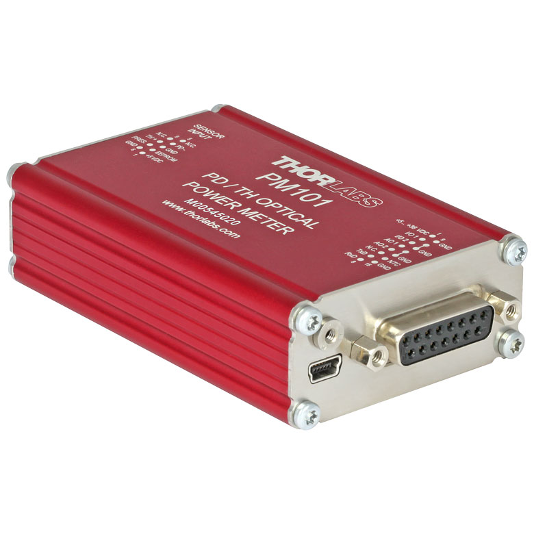
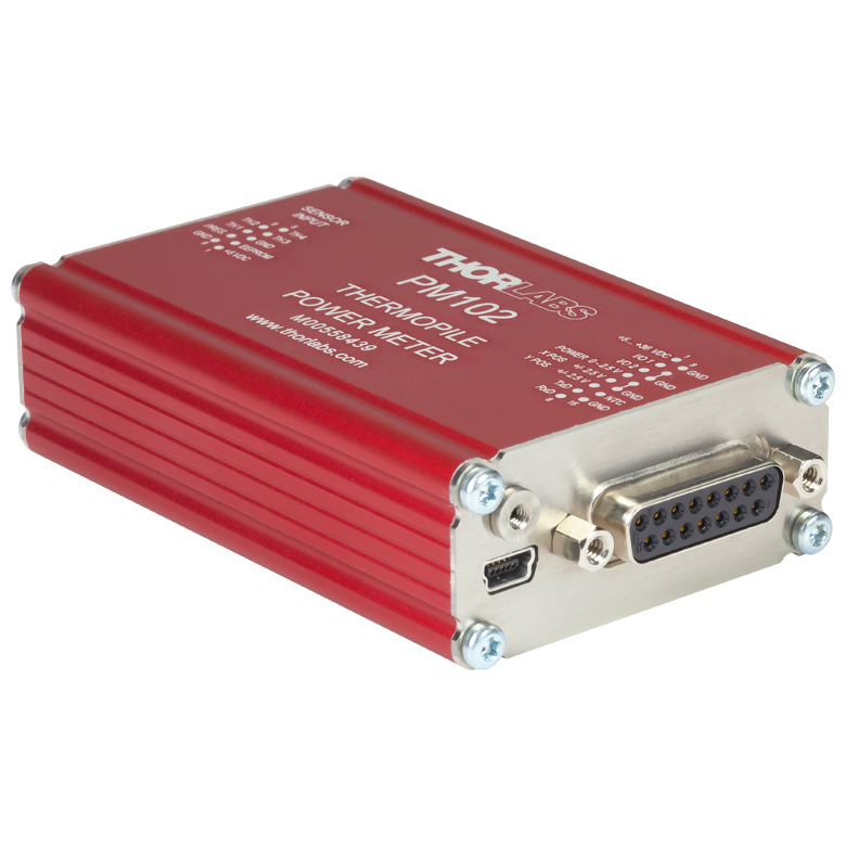
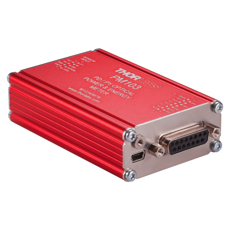
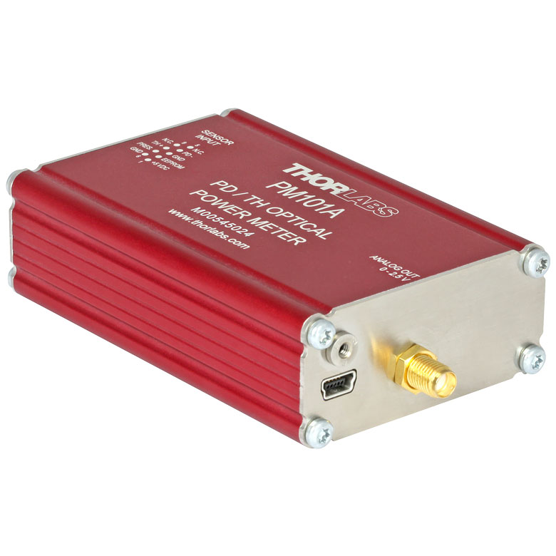
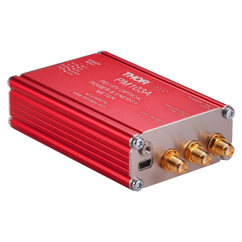
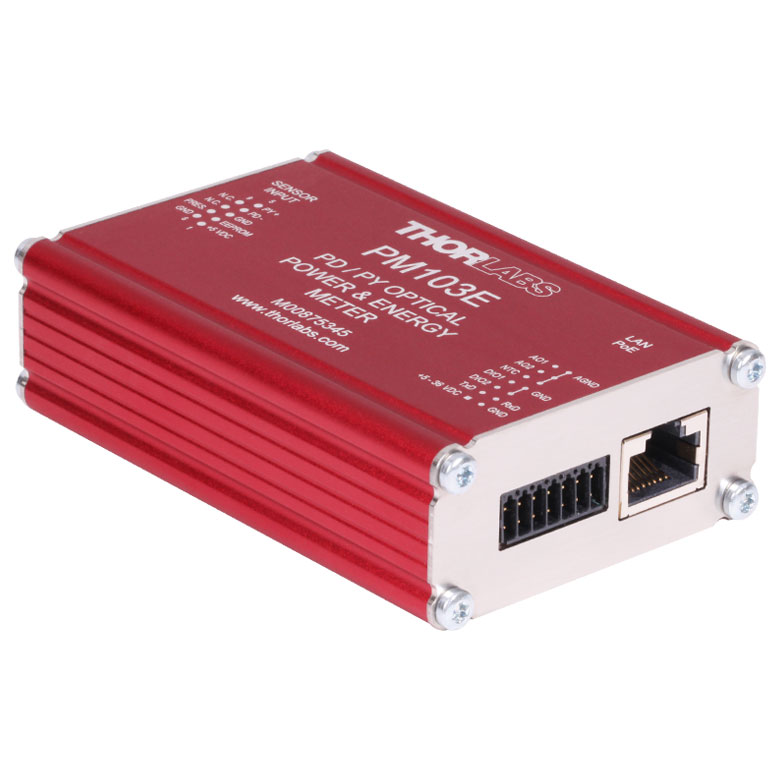
| Console Item # | PM100A | PM100D | PM400 | PM5020 | PM101 Series | PM102 Series | PM103 Series | PM100USB |
| Photodiode Power |  | | | | | - | | |
| Thermal Power | | | | | | | - | |
| Thermal Position | - | - | | | - | | - | - |
| Pyroelectric Energy | - | a | a | | - | - | | a |
パワー&エネルギーセンサのセレクションガイド
当社のパワー&エネルギーセンサの仕様を比較する際には、2種類の選択をします。下の表(展開します)では、当社のセンサを種類別に分類して(フォトダイオード、サーマル、焦電)、主な仕様を記載しています。
またその下のセレクションガイドのグラフでは、当社のフォトダイオードならびにサーマルパワーセンサの全ラインナップを波長範囲(左)そしてパワー範囲 (右)で比較できるようになっています。枠内には型番とセンサの仕様の範囲が記載されています。グラフにより、特定の波長範囲またはパワー範囲に適したセンサーヘッドが特定しやすくなっております。
| Photodiode Power Sensors |
|---|


| Thermal Power Sensors |
|---|


| Thermal Position & Power Sensors |
|---|

| Pyroelectric Energy Sensors |
|---|


センサのラインナップ
(波長範囲)
センサのラインナップ
(パワー範囲)
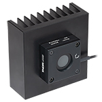
Click to Enlarge
S120C と簡単脱着マウントCP44F
- 一般的な光パワーの計測用
- センサのアライメントが容易になるビュワーターゲットを搭載
- センサの開口:Ø9.5 mm
- ファイバーアダプタは別売りでご用意
- センサ、保護キャップ、IRターゲットが付属
この標準フォトダイオードパワーセンサS12xCシリーズ は、UV域から近赤外域までの低いパワーのコヒーレント光/インコヒーレント光の測定にご使用いただけます。このセンサはNISTトレーサブル、校正済みで、アライメントが容易になるビュワーターゲットを搭載しており、電磁波干渉に対する遮蔽機能が強化され、過熱警報機能、Ø9.5 mmの大きな開口が特長です。Ø12 mm~Ø12.7 mm(Ø1/2インチ)ポストやSM1レンズチューブに取付け可能で、自由空間やファイバ出力光源の測定にも適しています。当社のSM1内ネジ付き 30 mmケージシステム用光学マウントをご使用いただくと30 mmケージシステムにも取り付け可能となります。
各センサはNISTまたはPTBトレーサブル校正データとともに発送いたします。ここに含まれるデータは、各センサのテストに使用するフォトダイオードの校正証明書のデータと同じです。当社ではこちらのフォトダイオードセンサの再校正サービスをご提供しております。詳細については、当社までお問い合わせください。
| Item #a | S120VC | S120C | S121C | S122Cb |
|---|---|---|---|---|
| Sensor Image (Click the Image to Enlarge) |
|
|
|
|
| Aperture Size | Ø9.5 mm | |||
| Wavelength Range | 200 - 1100 nm | 400 - 1100 nm | 400 - 1100 nm | 700 - 1800 nm |
| Power Range | 50 nW - 50 mW | 500 nW - 500 mW | 50 nW - 40 mW | |
| Detector Type | Si Photodiode (UV Extended) | Si Photodiode | Ge Photodiode | |
| Linearity | ±0.5% | |||
| Resolutionc | 1 nW | 10 nW | 2 nW | |
| Measurement Uncertaintyd | ±3% (440 - 980 nm) ±5% (280 - 439 nm) ±7% (200 - 279 nm, 981 - 1100 nm) | ±3% (440 - 980 nm) ±5% (400 - 439 nm) ±7% (981 - 1100 nm) | ±5% | |
| Responsivitye (Click for Plot) | Raw Data | Raw Data | Raw Data | Raw Data |
| Coating/Diffuser | Reflective ND (OD1.5)f | Reflective ND (OD1)g | Reflective ND (OD2)h | Absorptive ND (Schott NG9) |
| Head Temperature Measurement | NTC Thermistor 4.7 kΩ | |||
| Housing Dimensions | Ø30.5 mm x 12.7 mm | |||
| Active Detector Area | 9.7 mm x 9.7 mm | |||
| Cable Length | 1.5 m | |||
| Mounting Threadf,g,h | Universal 8-32 / M4 Tap, Post Not Included | |||
| Aperture Thread | External SM1 (1.035"-40) | |||
| Fiber Adapters | S120-FC2, S120-FC, S120-APC2, S120-APC, S120-SMA, S120-ST, S120-LC, S120-SC, and S120-25 (Not Included) | |||
| Compatible Consoles | PM400, PM100D, PM100A, and PM5020 | |||
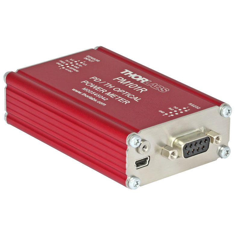
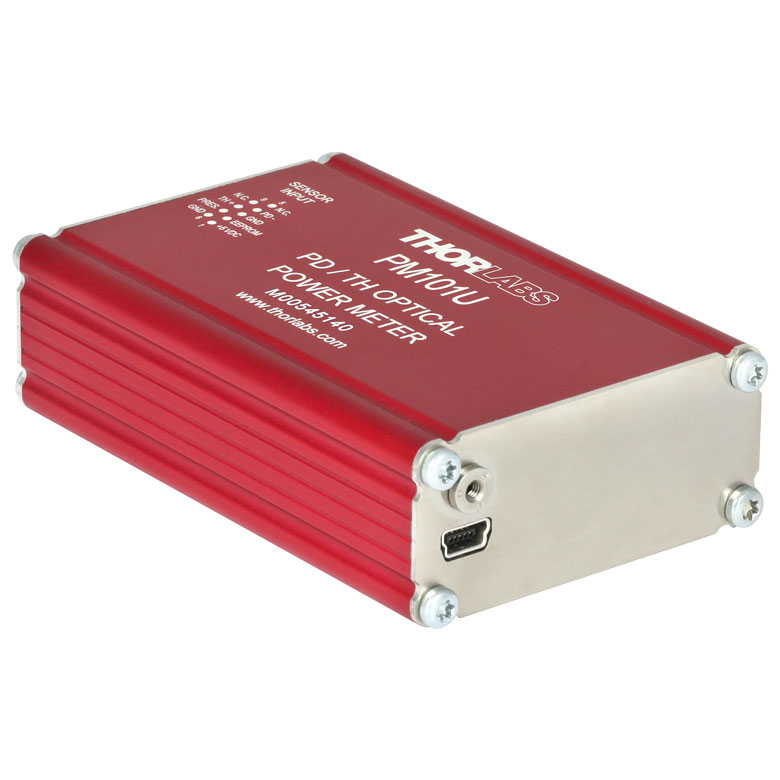
| Compatible Interfaces | PM101, PM101A, PM101R, PM101U, PM103, PM103A, PM103E, PM103U, and PM100USB | |||

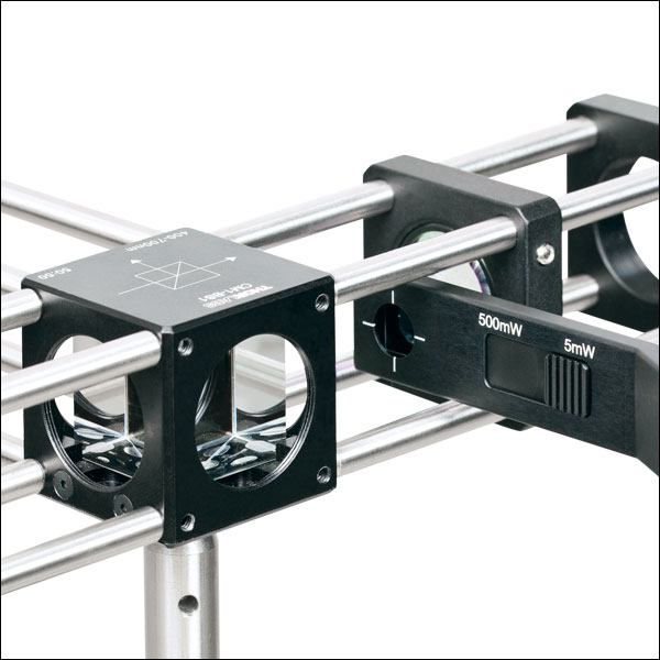
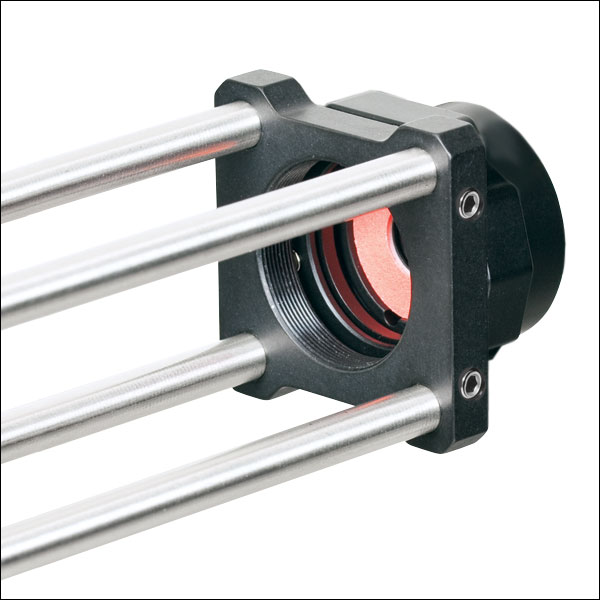
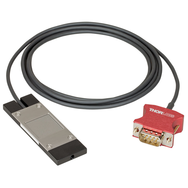
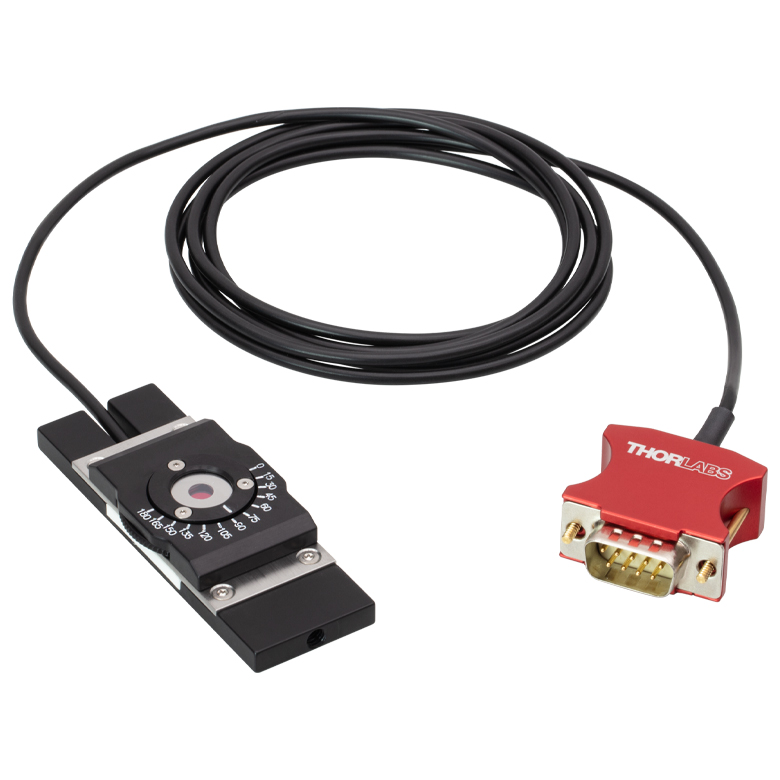
- 限られたスペースでの光パワーの測定に
- 薄型設計:センサの厚さ5 mm
- センサ開口部: 9.5 mm
- スライド式のNDフィルタがセンサのパワーレンジを自動調整
- 下記アクセサリも別途ご用意しております(下記参照)。
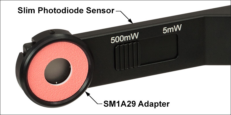
- VIS/赤外域用発光ターゲット付きのSM1外ネジアダプタSM1A29
- FiberBenchシステム用VIS/赤外域発光ターゲット付きマウントFBSM
S13xC シリーズ薄型フォトダイオードパワーセンサは、限られたスペースにおける光パワーの測定ができるように設計されています。 センサの厚さが僅か5 mmなので近接配置した光学素子の間やケージシステムの中ほか、標準のパワーメータを設置することのできない場所でもご使用になれます。 NISTトレーサブル校正済みセンサは、Ø9.5 mmの大きな開口が特長です。また、スライド式のNDフィルタが付いているため、コンパクトなデバイス1つで2つのパワー範囲を測定可能です。
S130シリーズのパワーセンサに、別売りのアダプタSM1A29を2つの止めネジ(セットスクリュ)で取り付けることにより、ファイバーアダプタ、遮光体、フィルタ他SM1シリーズのネジ付き部品を取り付けることが出来ます。マウントFBSMによりS130シリーズのパワーセンサがFiberBenchシステムに垂直方向に取り付けられるため、安定かつ最小の設置面積の取り付けとなります。
各センサはNISTまたはPTBトレーサブル校正データとともに発送いたします。ここに含まれるデータは、各センサのテストに使用するフォトダイオードの校正証明書のデータと同じです。当社ではこちらのフォトダイオードセンサの再校正サービスをご提供しております。詳細については、当社までお問い合わせください。
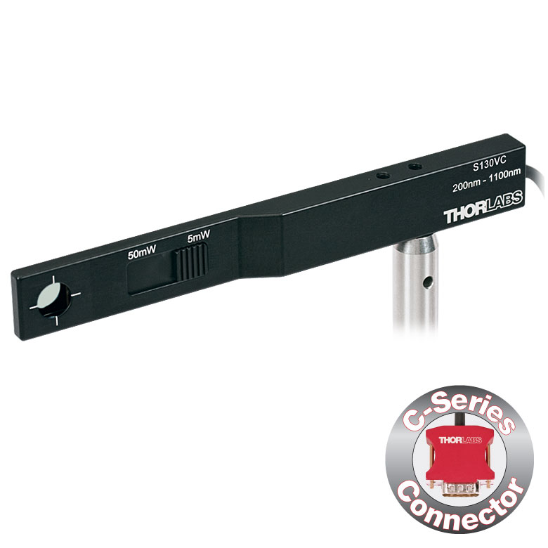
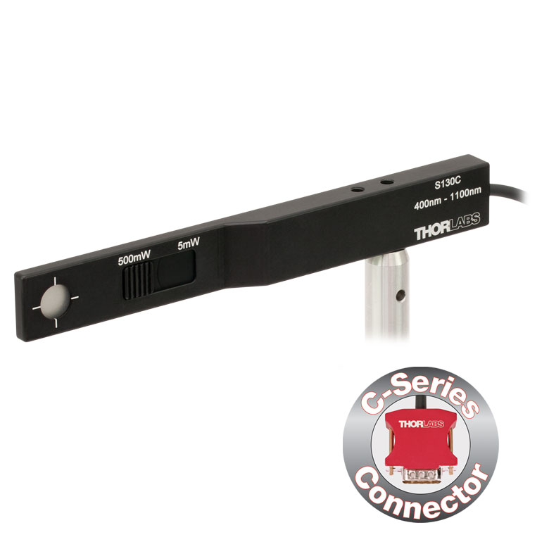
| Item #a | S130VC | S130C | S132Cb | |
|---|---|---|---|---|
| Sensor Image (Click the Image to Enlarge) |
|
|
| |
| Aperture Size | Ø9.5 mm | |||
| Wavelength Range | 200 - 1100 nm | 400 - 1100 nm | 700 - 1800 nmc | |
| Power Range (with Filter) | 500 pW - 0.5 mWd (Up to 50 mW)d | 500 pW - 5 mW (Up to 500 mW) | 5 nW - 5 mW (Up to 500 mW) | |
| Detector Type | Si Photodiode (UV Extended) | Si Photodiode | Ge Photodiode | |
| Linearity | ±0.5% | |||
| Resolution | 100 pWe | 1 nWf | ||
| Measurement Uncertaintyg | ±3% (440 - 980 nm) ±5% (280 - 439 nm) ±7% (200 - 279 nm, 981 - 1100 nm) | ±3% (440 - 980 nm) ±5% (400 - 439 nm) ±7% (981 - 1100 nm) | ±5% | |
| Responsivityh (Click for Plot) | Raw Data | Raw Data | Raw Data | |
| Coating/Diffuser | Reflective ND (OD1.5)d | Reflective ND (OD2)i | Absorptive ND (Schott NG9/KG3)c | |
| Housing Dimensions | 150 mm x 19 mm x 10 mm; 5 mm Thickness on Sensor Side | |||
| Active Detector Area | 9.7 mm x 9.7 mm | |||
| Cable Length | 1.5 m | |||
| Mounting Thread | Separate 8-32 and M4 Taps, Posts Not Included | |||
| Adapters (Not Included) | SM1A29: Add SM1 Thread and Viewing Target to Aperture Fiber Adapters Compatible with SM1A29 Adapter: S120-FC2, S120-FC, S120-APC2, S120-APC, S120-SMA, S120-ST, S120-LC, S120-SC, and S120-25 FBSM: Integrate Sensor into FiberBench Setups | |||
| Compatible Consoles | PM400, PM100D, PM100A, and PM5020 | |||
| Compatible Interfaces | PM101, PM101A, PM101R, PM101U, PM103, PM103A, PM103E, PM103U, and PM100USB | |||
| Item #a | S116C | |
|---|---|---|
| Sensor Image (Click the Image to Enlarge) |
| |
| Aperture Size | Ø6 mm | |
| Wavelength Range | 400 - 1100 nm | |
| Power Range | 20 nW - 50 mW | |
| Detector Type | Si Photodiode | |
| Linearity | ±0.5% | |
| Resolution | 1 nWb | |
| Measurement Uncertaintyc | ±3% (451 - 1000 nm) ±5% (400 - 450 nm, 1001 - 1100 nm) | |
| Responsivityd (Click for Plot) | Raw Data | |
| Coating/Diffuser | Absorptive ND (NG9) | |
| Housing Dimensions (L x W x T) | 70.0 mm x 11.0 mm x 8.9 mm; 10.0 mm Width and 4.5 mm Thickness on Sensor Side | |
| Active Detector Area | 7 mm x 7 mm | |
| Cable Length | 1.5 m | |
| Mounting Threads | 2 Universal 8-32 / M4 Taps (One on the Back, One on the Bottom), Posts Not Included | |
| Adapters (Not Included) | SM05A29: Add SM05 Thread to Aperture Fiber Adapters Compatible with SM05A29 Adapter: PM20-FC2, PM20-FC, PM20-APC2, PM20-APC, PM20-SMA, PM20-ST, PM20-SC, and PM20-LC, and PM20-25 | |
| Compatible Consoles | PM400, PM100D, PM100A, and PM5020 | |
| Compatible Interfaces | PM101, PM101A, PM101R, PM101U, PM103, PM103A, PM103E, PM103U, and PM100USB | |
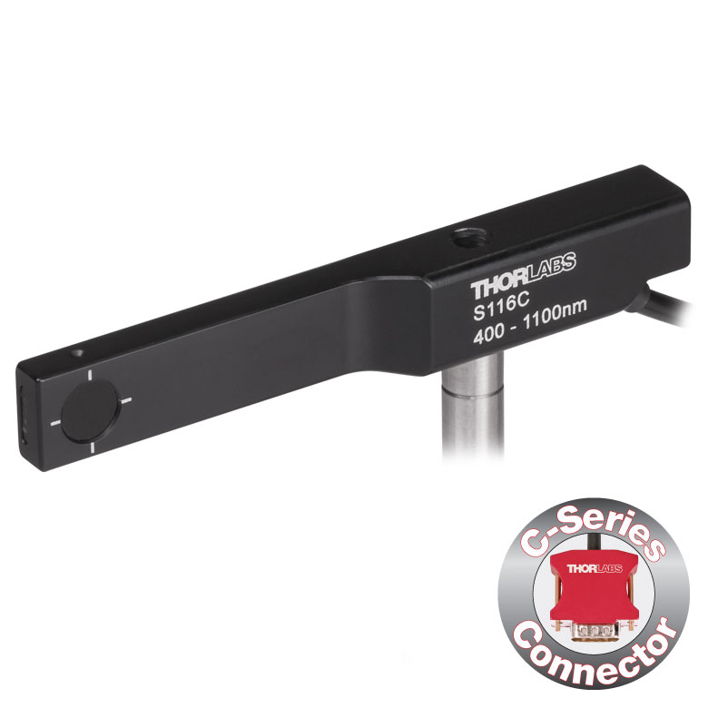
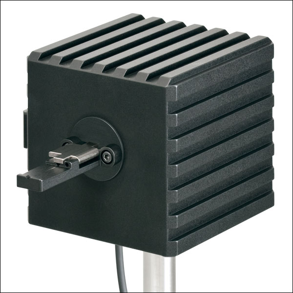
- 16 mmケージシステムなどの狭いスペースでの光パワー測定用
- 波長範囲:400~1100 nm
- 超薄型設計:センサ部の幅10.0 mm、厚さ4.5 mm
- シリコン(Si)フォトダイオード、センサ開口Ø6 mm
- 低パワーレーザ光のパワー測定用
- ポスト取付け用のM4タップ穴
- SM05外ネジ付きアダプタSM05A29は別売りでご用意(下記参照)
コンパクト薄型フォトダイオードパワーセンサS116Cは、スペースやアクセス性が制限された場面でも光パワーが測定できるように設計されています。厚さ4.5 mmのフォトダイオードセンサは、16 mmケージシステムのケージロッドの間(下の写真参照)や、スロット付きØ12 mm~Ø12.7 mm(Ø1/2インチ)レンズチューブ(型番SM05L20CおよびSM05L30C)の側面の穴から挿入することができます。このセンサの開口径はØ6 mmです。
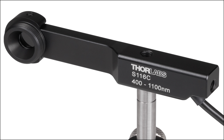
パワーセンサS116Cに、別売りのアダプタSM1A29を2本の1.3 mm六角止めネジ(セットスクリュ)で取り付けると、ファイバーアダプタ、遮光体、フィルタなどのSM05ネジ付き部品を取り付けることができます。アダプタを取り付けたパワーセンサS116Cの写真が下でご覧いただけます。
各センサはNISTまたはPTBトレーサブル校正データとともに発送いたします。ここに含まれるデータは、校正対象センサのスペクトル範囲に対応する、認定された参照用ダイオードを利用して決定されています。当社では、フォトダイオードパワーセンサの再校正サービスをご提供しています。詳細は当社までお問い合わせください。
Click for Details
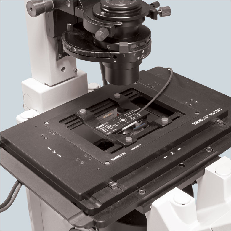
Using the engraved alignment target on the back of the sensor housing, a user can position the stage so that when the sensor is flipped, the beam strikes the center of the sensor. The S170C sensor is shown in this image.
- Designed to Measure Optical Power at the Sample Plane of a Microscope
- Silicon Photodiode with Large 18 mm x 18 mm Active Area
- Sensor Housing Dimensions: 76.0 mm x 25.2 x 5.0 mm
- Novel Optical Design Accommodates High NA Objectives
- Information Stored in Connector
- Sensor Data
- NIST- and PTB-Traceable Calibration Data
- Post Mountable via 8-32 (M4 x 0.7) Tap
The Microscope Slide Power Sensor Heads with silicon photodiodes are designed to measure the power at the sample plane in microscopy setups. The S170C sensor can detect wavelengths from 350 nm to 1100 nm at optical powers from 10 nW to 150 mW, while the S171C sensor can detect wavelengths from 400 nm to 1100 nm at powers from 1 nW to 15 mW. The NS170C sensor is designed to measure the relative peak power of femtosecond lasers with center wavelengths from 780 nm to 1300 nm and average powers from 0.5 mW to 350 mW. Each sensor head's 76.0 mm x 25.2 mm footprint matches that of a standard microscope slide and is compatible with most standard upright and inverted microscopes.
The photodiodes used in the S170C and S171C sensors have 18 mm x 18 mm active areas and are contained in sealed housings behind neutral density (ND) filters. A 20 mm x 20 mm indentation around the surface of the ND filter is sized to accept standard microscope cover slips. An immersion medium (water, glycerol, oil) may be placed in this well directly over the ND filter, or a cover slip may be inserted first to simplify clean up. The gap between the photodiode and the neutral density filter has been filled with an index matching gel in order to prevent internal reflections from causing significant measurement errors when using high NA objectives with oil or water.
The NS170C sensor is designed to measure the relative peak power of two-photon lasers by utilizing a second-order nonlinear β-BBO crystal to convert incident ultrafast NIR pulses into their visible second harmonic. Shortpass filters underneath the β-BBO crystal reject the residual NIR light, allowing only the second harmonic light to transmit down to a large area silicon photodiode sensor. At the entrance of the sensor is a 170 µm thick cover glass sealed to the sensor housing, allowing the sensor to be used with dry, water immersion, and oil immersion objectives. The working distance from the top of the cover glass to the β-BBO crystal is 0.22 mm.
The bottom of each sensor housing features a laser-engraved grid to aid in aligning and focusing the beam. In standard microscopes, this grid can be used for beam alignment before flipping the sensor head to face the objective for power measurements. In inverted microscopes, turn on the transmitted illuminator to align the grid on the detector housing with the beam, thereby centering the sensor in front of the objective. Alternatively, the diffusive surface of the ND filter can be used as a focusing plane.
To avoid damaging the sensor, we recommend positioning it in the light path at a location where the beam is not focused. It is important not to exceed the Max Average Power Density over the beam's spot size for the S170C and S171C sensors, and the Max Peak Power Density for the NS170C sensor (see Specs tab) .
Each sensor is shipped with NIST- or PTB-traceable calibration data. The included data will match the calibration certification of the photodiode used to test the individual sensor. Sensor specifications and the included NIST- or PTB-traceable calibration data are stored in non-volatile memory in the sensor connector and can be read out by the latest generation of Thorlabs power meters. Please note that the NS170C sensor's NIST and PTB calibration is for the visible light incident on the detector; however, the magnitude of that visible light is specific to the illumination conditions of the NIR femtosecond pulses. We recommend yearly recalibration to ensure accuracy and performance. For recalibration of the S170C and S171C sensors, Item # CAL-PD can be ordered below. For more information on recalibrating the NS170C sensor, please contact Tech Support.
The complete set of specifications are presented on the Specs tab above. Thorlabs also offers a Microscope Slide Sensor Head with a thermal sensor; the full presentation can be found here.
| Item #a | S170C | S171C | NS170C |
|---|---|---|---|
| Sensor Image (Click Image to Enlarge) |
 |
 |
 |
| Dimensions | 76.0 mm x 25.2 mm x 5.0 mm (2.99" x 0.99" x 0.20") |
Base: 76.0 mm x 25.2 mm x 5.0 mm (2.99" x 0.99" x 0.20") Overall: 76.0 mm x 30.0 mm x 11.0 mm (2.99" x 1.18" x 0.43") |
|
| Active Detector Area | 18 mm x 18 mm | ||
| Input Aperture | 20 mm x 20 mm | Ø4.5 mm | |
| Wavelength Range | 350 - 1100 nm | 400 - 1100 nm | Laser: 780 - 1300 nm SHG: 390 - 650 nm |
| Optical Power Working Range | 10 nW - 150 mW | 1 nW - 15 mW | Laser: 0.5 - 350 mWb SHG: 10 nW - 5 mW |
| Max Peak Power Densityc | - | - | 10 TW/cm2 |
| Detector Type | Silicon Photodiode | Second-Order Nonlinear Crystal with Silicon Photodiode |
|
| Linearity | ±0.5% | ±0.5%d | |
| Resolution | 1 nWe | 0.5 pWf | 1 nWd,e |
| Measurement Uncertaintyg | ±3% (440 - 980 nm) ±5% (350 - 439 nm) ±7% (981 - 1100 nm) |
±3% (440 - 980 nm)h ±5% (400 - 439 nm)h ±7% (981 - 1100 nm)h |
±3% (440 - 650 nm)d ±5% (390 - 439 nm)d |
| Responsivityi (Click for Plot) |
Raw Data |
Raw Data |
Raw Data |
| Neutral Density Filter | Reflective (OD 1.5) | Absorptive (OD 0.4) | N/A |
| Cable Length | 1.5 m | ||
| Mounting Thread | Universal 8-32 / M4 x 0.7 Tap, Post Not Included | ||
| Compatible Consoles | PM400, PM100D, PM100A, and PM5020 | ||
| Compatible Interfaces | PM101, PM101A, PM101R, PM101U, PM103, PM103A, PM103E, PM103U, and PM100USB | ||
Click to Enlarge
ファイバ素線用アダプタS140-BFA(別売り)を取り付けたS142C
Click to Enlarge
ファイバーアダプタS120-FC(付属)を取り付けたS142C
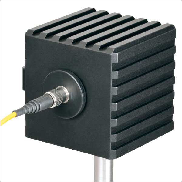
- ビーム形状や入射角の影響を受けない測定が可能
- 積分球方式により光損失を最小に抑えた拡散板として機能
- センサの入射開口径:Ø5 mm、Ø7 mm、Ø12 mmまたはØ22 mm
- 開口径≤Ø12 mmの積分球には取外し可能なファイバーアダプタS120-FC(FC/PCまたはFC/APCの取付けが可能)が付属
- 開口径≤Ø12 mmの積分球には、終端処理済みファイバ用およびファイバ素線用のアダプタ(下表参照)の取付けが可能
積分球フォトダイオードパワーセンサは、入射するビームの均一性、広がり角、形状、入射角などに依存せずにパワーを測定するのに適しており、ファイバ光源からの光や光軸から外れた自由空間光などのパワー測定用として優れています。電磁干渉を抑制するためにシールドが強化されており、またセンサの加熱による損傷や測定エラーを防止するために過熱警告センサが付いています。
当社の積分球は、可視~近赤外の波長域用に設計されています。350~2500 nm用のセンサーヘッドには、Zenith® PTFE製のØ25.4 mm(Ø1インチ)またはØ50.8 mm(Ø2インチ)の単一の球が使用されており、入射開口部周辺での反射光を最小限に抑えるために筐体は黒色になっています。波長範囲350~1100 nm用の光検出センサとしてはシリコン(Si)フォトダイオードを、波長範囲800~1700 nm、900~1650 nm、または1200~2500 nm用の光検出センサとしてはInGaAsフォトダイオードを使用しています。
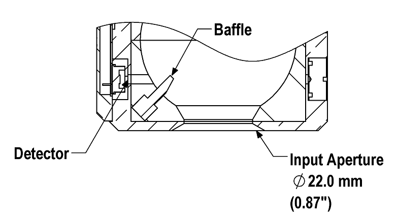
2.9~5.5 µm用の積分球S180Cでは、金メッキされたØ20 mmの球を2つ接続して使用しています。1つめの球に入射ポートが付いており、MCT (HgCdTe)ディテクタ用のポートは2つ目の球に付いています。2つの球を用いる方式では、単一の球を用いる方式と比べると、ディテクタが入射光に直接晒されないように効果的に遮光できるだけでなく、内部の球の表面積を最小限に抑えることもできるため、検出器としての感度が向上します。この方式では、バッフルやその他の遮光機構を使用しなくても、フォトダイオードへの直接入射光を効果的に遮蔽できるため、入射角、広がり角、ビーム形状などによる測定への影響を低減できます。
Click to Enlarge
S142CLとS145CLでは、ディテクタに直接光が入射しないようにバッフルを用いて遮光しています。
開口径が Ø5 mm、Ø7 mmまたはØ12 mmの積分球には大きな受光面積の検出器が付いており、また付属のファイバーアダプタS120-FCを取り付けられるSM1外ネジ付きアダプタが付いています。これらのセンサの検出器の受光面積が大きいため、付属のファイバーアダプタS120-FCにはFC/PCまたはFC/APCコネクタ付きファイバを接続することができます。SM1外ネジ付きアダプタはサイズ1のスクリュードライバを使用して取り外せるため、コンポーネントをウィンドウの近くに設置することができます。
積分球S142CLとS145CLの入射開口径はØ22 mmと大きいですが、積分球内のバッフルでフォトダイオードに光が直接入射しないように遮光しています。大きな開口径とバッフルの組み合わせにより、LEDやVCSELのような面積と発散角の大きな光源からの光も測定可能です。ディテクタの入射面には、30 mmケージシステム部品を取り付けるための4つの#4-40ネジが付いています。また、ご要望により、センサーヘッドに第2あるいは第3のポートを付けることも可能です。詳細は当社までお問い合わせください。
各センサにはNISTまたはPTBにトレーサブルな校正データが付いています。それらのデータは、各センサの試験に使用されたフォトダイオードの校正証明書のデータと同じです。NISTまたはPTBにトレーサブルなデータはセンサーコネクタ内に保存されています。当社では、フォトダイオードパワーセンサの再校正サービスをご提供しています。詳細は当社までお問い合わせください。
| Item #a | S140C | S142C | S142CL | S144C | S145C | S145CL | S146C | S148C | S180C | |
|---|---|---|---|---|---|---|---|---|---|---|
| Sensor Image (Click the Image to Enlarge) | 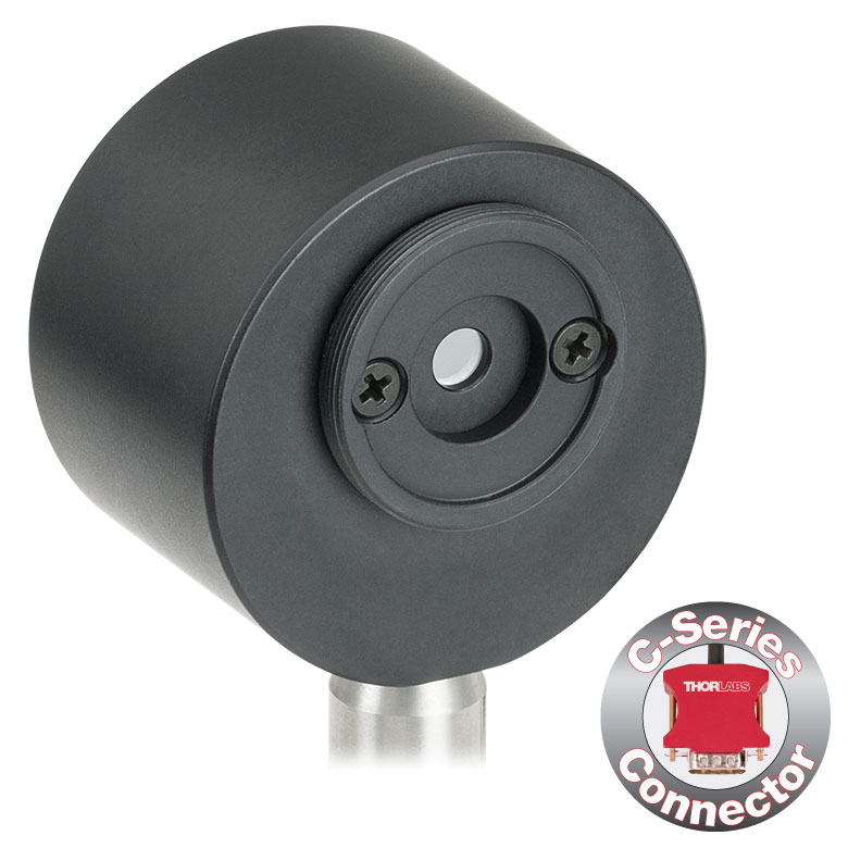 | 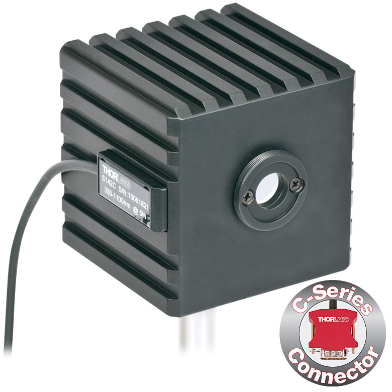 | 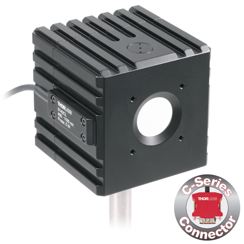 |  | 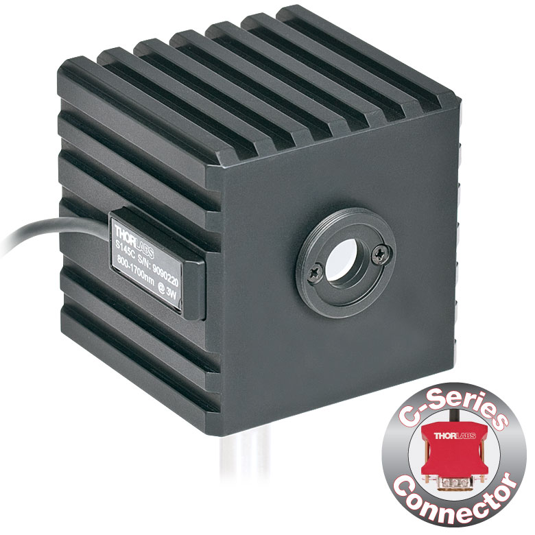 | 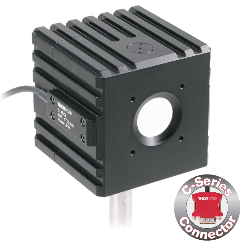 | 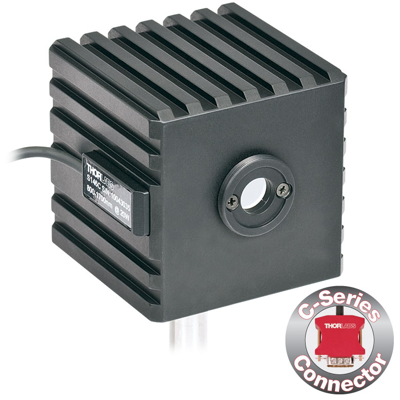 | | 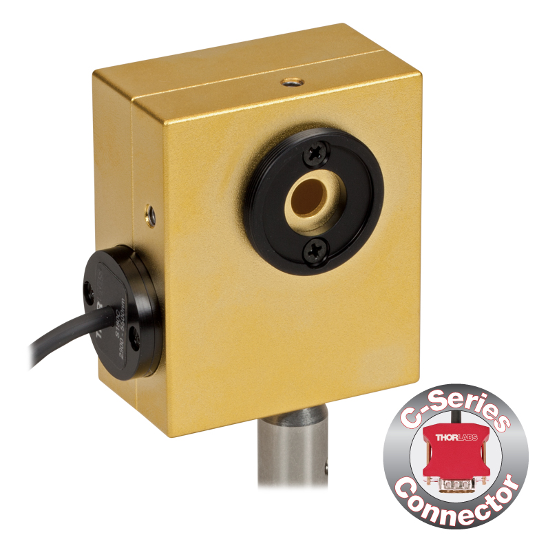 | |
| Aperture Size | Ø5 mm | Ø12 mm | Ø22 mm | Ø5 mm | Ø12 mm | Ø22 mm | Ø12 mm | Ø5 mm | Ø7 mm | |
| Wavelength Range | 350 - 1100 nm | 400 - 1100 nm | 800 - 1700 nm | 900 - 1650 nm | 1200 - 2500 nm | 2.9 µm - 5.5 µm | ||||
| Power Range | 1 µW - 500 mW | 1 µW - 5 W | 10 µW - 5 W | 1 µW - 500 mW | 1 µW - 3 W | 10 µW - 3 W | 10 µW - 20 W | 1 µW - 1 W | 1 µW - 3 W | |
| Detector Type | Si Photodiode | Si Photodiode with Baffle | InGaAs Photodiode | InGaAs Photodiode with Baffle | InGaAs Photodiode | Extended InGaAs Photodiode | MCT (HgCdTe) Photodiode | |||
| Linearity | ±0.5% | |||||||||
| Resolutionb | 1 nW | 10 nW | 1 nW | 10 nW | 1 nW | 10 nW | ||||
| Measurement Uncertaintyc,d | ±3% (440 - 980 nm) ±5% (350 - 439 nm) ±7% (981 - 1100 nm) | ±3% (440 - 980 nm) ±5% (400 - 439 nm) ±7% (981 - 1100 nm) | ±5% | |||||||
| Responsivitye (Click for Plot) | Raw Data | Raw Data | Raw Data | Raw Data | Raw Data | Raw Data | Raw Data | Raw Data | Raw Data | |
| Integrating Sphere Material (Size) | Zenith® PTFE (Ø1") | Zenith® PTFE (Ø2") | Zenith® PTFE (Ø1") | Zenith® PTFE (Ø2") | Zenith® PTFE (Ø1") | Gold Plating (Two Ø20 mm Spheres) | ||||
| Head Temperature Measurement | NTC Thermistor 4.7 kΩ | |||||||||
| Housing Dimensions | Ø45 mm x 30.5 mm | 70 mm x 74 mm x 70 mm | Ø45 mm x 30.5 mm | 70 mm x 74 mm x 70 mm | Ø45 mm x 30.5 mm | 59.0 mm x 50.0 mm x 28.5 | ||||
| Active Detector Area | 3.6 mm x 3.6 mm | Ø2 mm | Ø3 mm | Ø1 mm | Ø1 mm | 1 mm x 1 mm | ||||
| Cable Length | 1.5 m | |||||||||
| Mounting Thread | Separate 8-32 and M4 Taps, Posts Not Included | Universal 8-32 / M4 Thread, Post Not Included | Separate 8-32 and M4 Taps, Posts Not Included | Universal 8-32 / M4 Thread, Post Not Included | Separate 8-32 and M4 Taps, Posts Not Included | Universal | ||||
| Aperture Thread | Included Adapter with SM1 (1.035"-40) External Thread | None | Included Adapter with SM1 (1.035"-40) External Thread | None | Included Adapter with SM1 (1.035"-40) External Thread | |||||
| Compatible Fiber Adapters | S120-FC (Included) S120-FC2, S120-APC2, S120-APC, S120-SMA, S120-ST, S120-SC, S120-LC, S120-25, and S140-BFA (Not Included) | None | S120-FC (Included) S120-FC2, S120-APC2, S120-APC, S120-SMA, S120-ST, S120-SC, S120-LC, S120-25, and S140-BFA (Not Included) | None | S120-FC (Included) S120-FC2, S120-APC2, S120-APC, S120-SMA, S120-ST, S120-SC, S120-LC, S120-25, and S140-BFA (Not Included) | |||||
| Compatible Consoles | PM400, PM100D, PM100A, and PM5020 | |||||||||
| Compatible Interfaces | PM101, PM101A, PM101R, PM101U, PM103, PM103A, PM103E, PM103U, and PM100USB | |||||||||

 ズーム
ズーム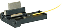

Click to Enlarge
PM100D、センサS150CとFCケーブル
- ファイバ接続による光パワー測定用
- 小型センサがコネクタ内部に収納
- 現場や研究室で使い易い設計
- FC/PCファイバーアダプタが付属
- センサS150CならびにS151CにはSMAファイバーアダプタも付属
- FC/APC、LC/PC、SC/PCおよびST®*ファイバーアダプタもご用意しております(下表をご覧ください)。
- 対応するコンソール:PM100D、PM100USB、PM100A
S15xCシリーズのファイバ用小型フォトダイオードパワーセンサは、様々なファイバ出力光源のパワー測定用に設計されています。パワーメーターコネクタに内蔵されているこの小型センサは、フォトダイオードセンサ、ファイバ入力部、NISTまたはPTBトレーサブル校正データを納めるユニークな設計となっています。各センサに付属するファイバーアダプタは簡単に交換できるため、様々なファイバーコネクタに対応します(下表参照)。
各センサはNISTまたはPTBトレーサブル校正データとともに発送いたします。ここに含まれるデータは、各センサのテストに使用するフォトダイオードの校正証明書のデータと同じです。当社ではこちらのフォトダイオードセンサの再校正サービスをご提供しております。詳細については、当社までお問い合わせください。
*ST®はLucent Technologies社の登録商標です。
| Item #a | S150C | S151C | S154C | S155C |
|---|---|---|---|---|
| Sensor Image (Click the Image to Enlarge) |
|
|
|
|
| Wavelength Range | 350 - 1100 nm | 400 - 1100 nm | 800 - 1700 nm | |
| Power Range | 100 pW to 5 mW (-70 dBm to +7 dBm) | 1 nW to 20 mW (-60 dBm to +13 dBm) | 100 pW to 3 mW (-70 dBm to +5 dBm) | 1 nW to 20 mW (-60 dBm to +13 dBm) |
| Detector Type | Si Photodiode | InGaAs Photodiode | ||
| Linearity | ±0.5% | |||
| Resolutionb | 10 pW (-80 dBm) | 100 pW (-70 dBm) | 10 pW (-80 dBm) | 100 pW (-70 dBm) |
| Measurement Uncertaintyc | ±3% (440 - 980 nm) ±5% (350 - 439 nm) ±7% (981 - 1100 nm) | ±3% (440 - 980 nm) ±5% (400 - 439 nm) ±7% (981 - 1100 nm) | ±5% | |
| Responsivityd (Click for Details) | Raw Data | Raw Data | Raw Data | Raw Data |
| Coating/Diffuser | N/A | Absorptive ND (Schott NG3) | N/A | |
| Head Temperature Measuremente | NTC Thermistor 3 kΩ | |||
| Aperture Thread | External SM05 (0.535"-40) | |||
| Fiber Adaptersf | Included (FC and SMA): PM20-FC and PM20-SMA; Optional: PM20-FC2, PM20-APC2, PM20-APC, PM20-ST, PM20-SC,PM20-LC, and PM20-25 | Included (FC): PM20-FC; Optional: PM20-FC2, PM20-APC2, PM20-APC, PM20-SMA, PM20-ST, PM20-SC, PM20-LC, and PM20-25 | ||
| Compatible Consoles | PM400, PM100D, PM100A, and PM5020 | |||
| Compatible Interfaces | PM101, PM101A, PM101R, PM101U, PM103, PM103A, PM103E, PM103U, and PM100USB | |||

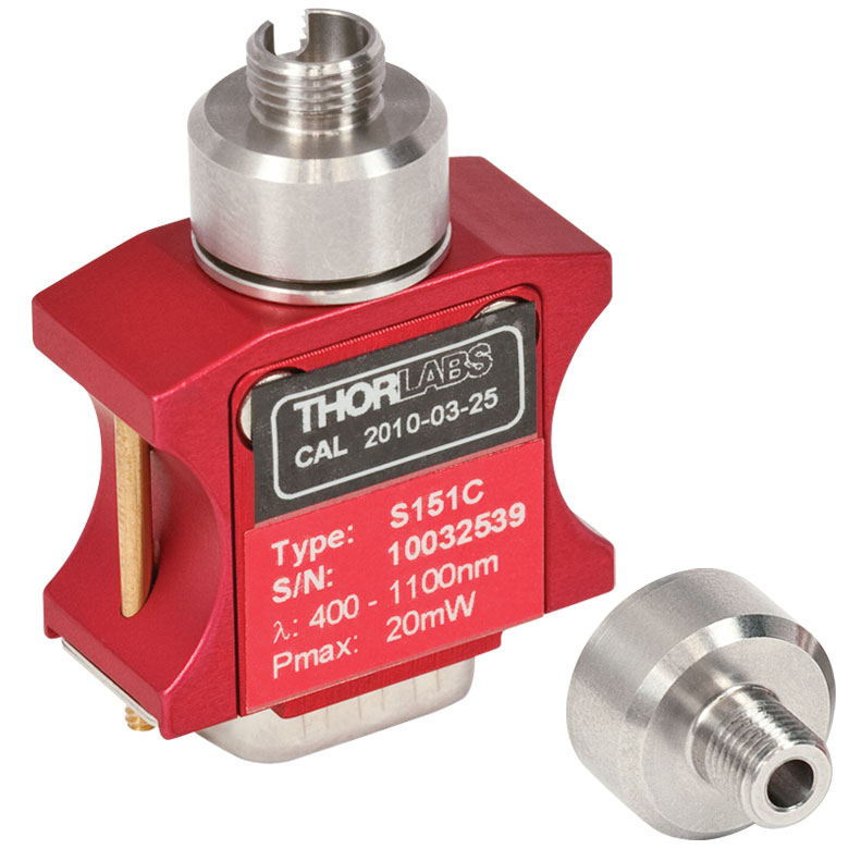
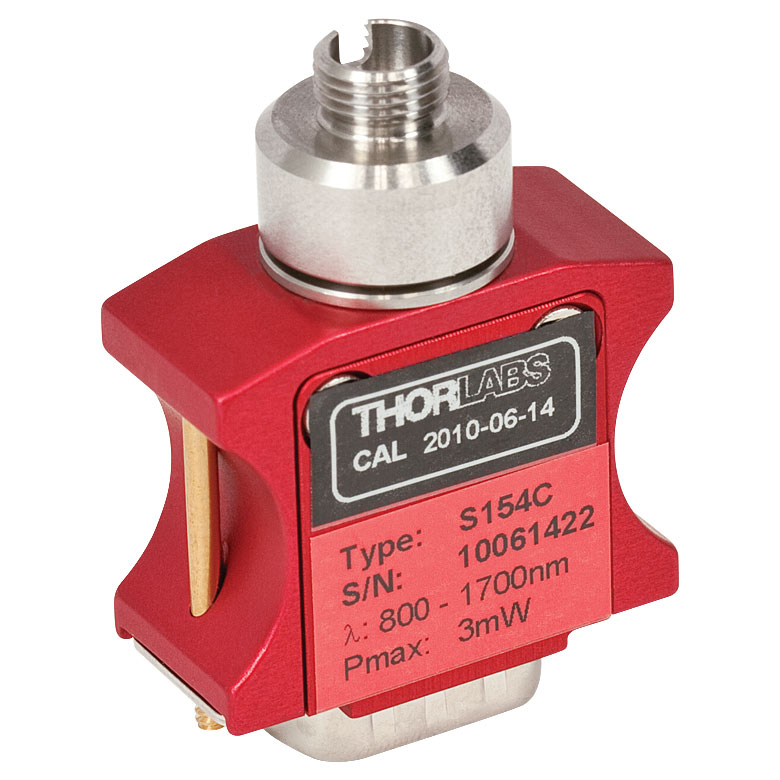

こちらのSM05内ネジ付きファイバーアダプタは、コネクタ付きファイバと、下記を含む当社の多くの自由空間型ディテクタやパワーセンサなど含む様々な製品と結合させることができます。
ナローキーとワイドキーの詳細については、光ファイバとはのページをご覧ください。対応製品についてご不明な点がありましたら、お気軽に当社までお問い合わせください。
フェルール用アダプタPM20-25は、ロッキングコネクタ機構無しの設計になっています。Ø2.5 mmフェルール付きのファイバーパッチケーブルに対応し、パワーメータでの測定を迅速に行うことができます。
| Item # | PM20-FC2 | PM20-FC | PM20-APC2a | PM20-APCa | PM20-SMA | PM20-ST | PM20-SC | PM20-LC | PM20-25 |
|---|---|---|---|---|---|---|---|---|---|
| Adapter Image (Click the Image to Enlarge) |  |  |  |  |  |  | 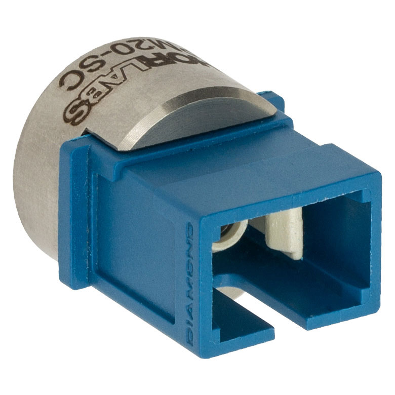 |  |  |
| Connector Type | FC/PC, 2.0 mm Narrow Key | FC/PC, 2.2 mm Wide Key | FC/APC, 2.0 mm Narrow Key | FC/APC, 2.2 mm Wide Key | SMA | ST®b/PC | SC/PCc | LC/PC | Ø2.5 mm Ferrule |
| Threading | Internal SM05 (0.535"-40) | ||||||||
こちらのSM1内ネジ付きアダプタはフォトダイオードパワーセンサ、サーマルパワーセンサ、そしてフォトディテクタをはじめとする当社の全てのSM1外ネジ付き部品とコネクタ付きファイバを接続させることができます。
ナローキーとワイドキーの詳細については、光ファイバとはのページをご覧ください。アダプタが取り付け可能かどうかが不確かな場合には当社までご連絡くさい。
APCアダプタには 2つの窪みがあるので、どちらの面からもスパナレンチSPW909またはSPW801を用いて締め付け可能です。このアダプタをSM1レンズチューブと遮光用途でお使いいただけるように、窪みはディスクを貫通していません。
フェルール用アダプタS120-25は、ロッキングコネクタ機構無しの設計になっています。Ø2.5 mmフェルール付きのファイバーパッチケーブルに対応し、フォトディテクタやパワーセンサを用いた測定を迅速に行うことができます。
| Item # | S120-FC2 | S120-FC | S120-APC2a | S120-APCa | S120-SMA | S120-ST | S120-SC | S120-LC | S120-25 |
|---|---|---|---|---|---|---|---|---|---|
| Adapter Image (Click the Image to Enlarge) | 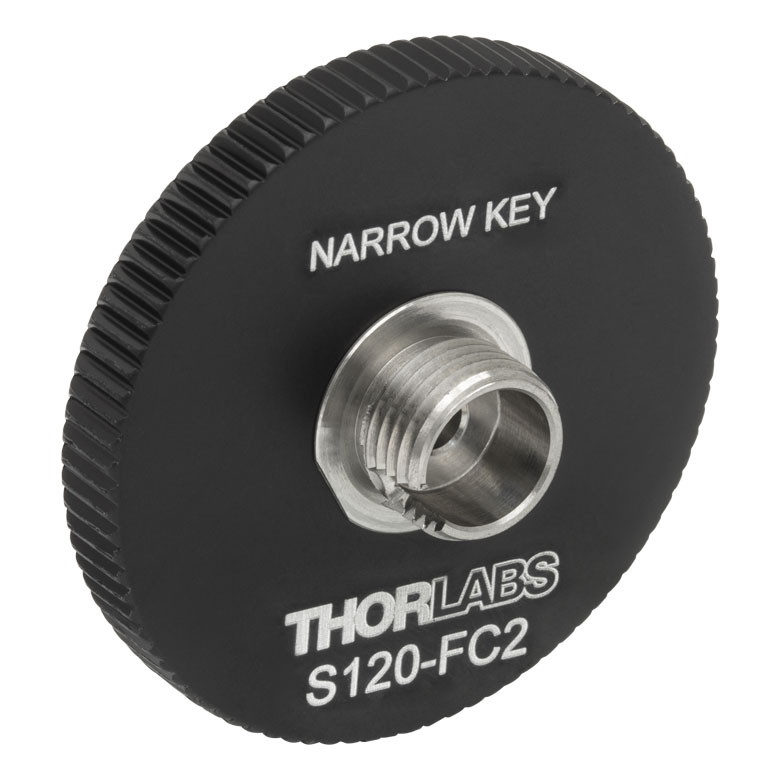 | 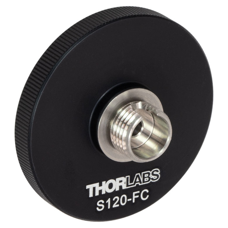 | 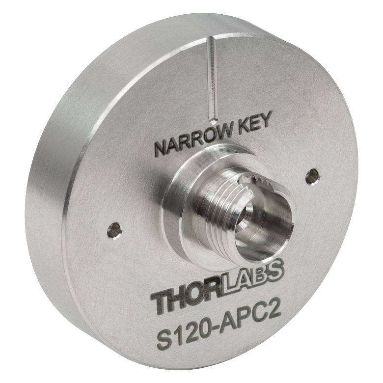 | 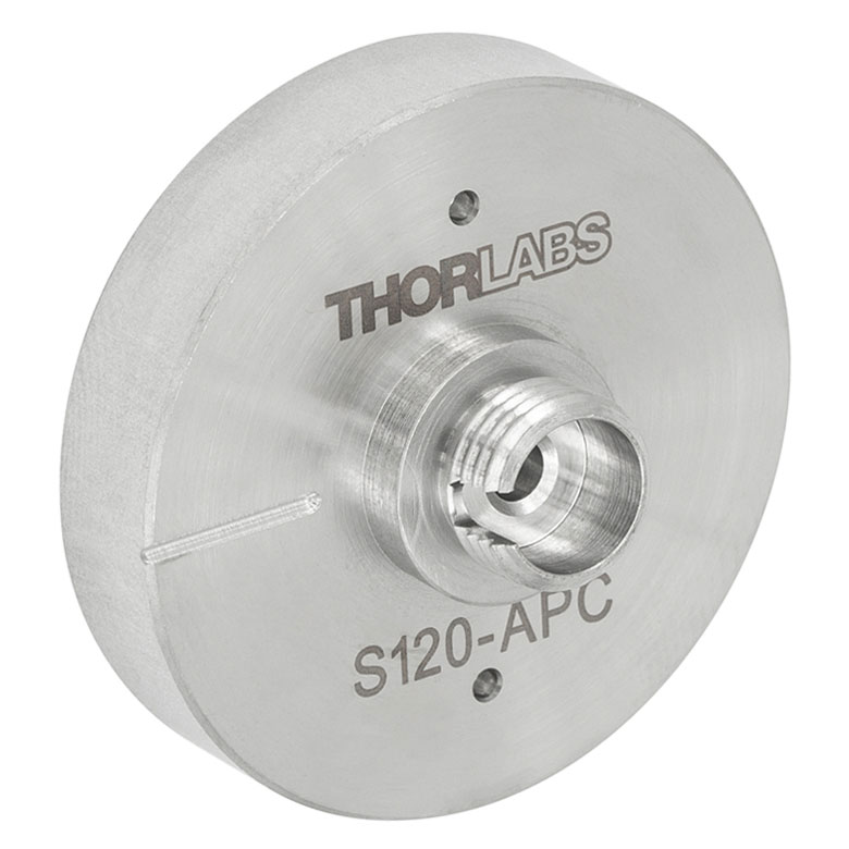 | 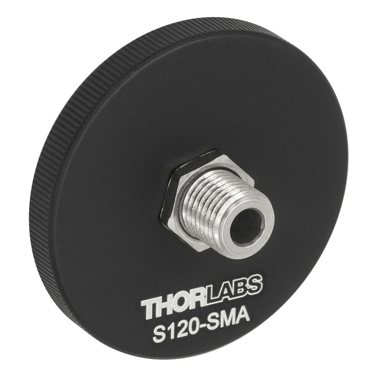 | 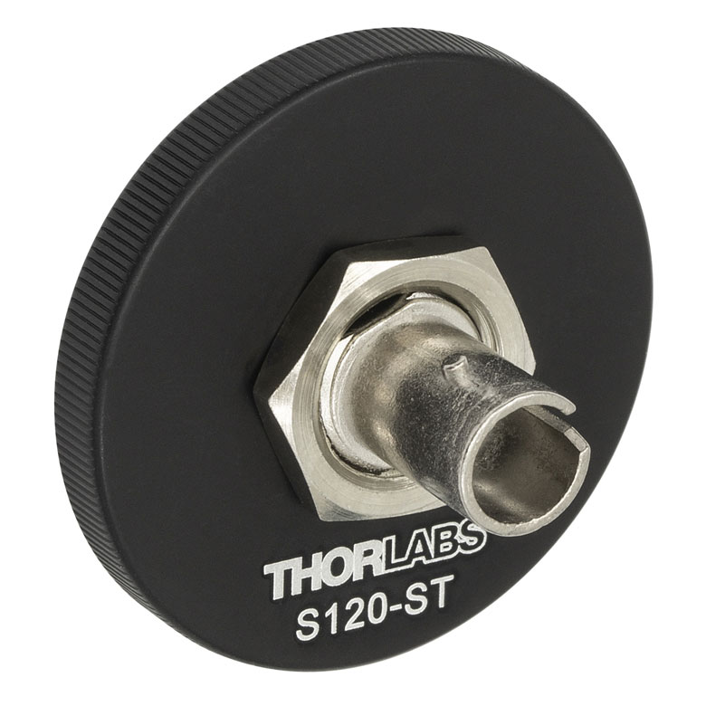 | 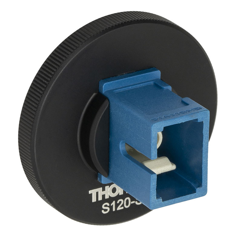 | 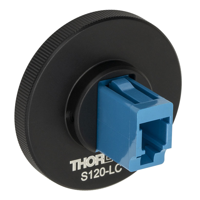 |  |
| Fiber Connector Type | FC/PC, 2.0 mm Narrow Key | FC/PC, 2.2 mm Wide Key | FC/APC, 2.0 mm Narrow Key | FC/APC 2.2 mm Wide Key | SMA | ST®b/PC | SC/PCc | LC/PC | Ø2.5 mm Ferrule |
| Threading | Internal SM1 (1.035"-40) | ||||||||

 ズーム
ズーム
Click to Enlarge
アダプタSM1A29を用いてレンズチューブを取り付けたフォトダイオードセンサS132C
- 当社の薄型フォトダイオードパワーセンサに対応
- SM1内ネジ付き部品への組み込みが可能
- センサの周囲にVIS/IRターゲットを追加
アダプタSM1A29は、0.9 mm六角レンチに対応する2個の止めネジ(セットスクリュ)を使って当社の薄型フォトダイオードセンサに取り付け可能です。これにより、SM1内ネジ付きファイバーアダプタ、フィルタ、他のSM1ネジ付きメカニクスや光学素子を薄型フォトダイオードセンサに取り付けることができます。開口周りにあるターゲットには、当社のレーザービュワーカードVRC2と同じ材料を使用しています。400~645 nmと800~1700 nmの波長範囲で感度があります。

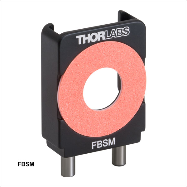 ズーム
ズーム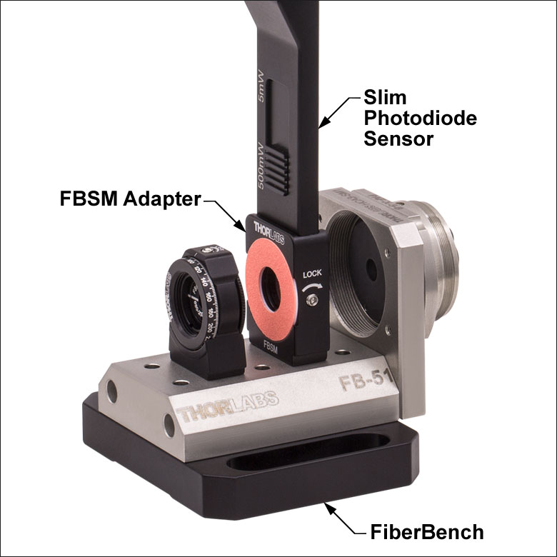
Click for DetailsアダプタFBSMを使用してFiberBenchシステムに取り付けたフォトダイオードセンサS130C
- 当社の薄型フォトダイオードパワーセンサに対応
- 1軸ならびに多軸FiberBenchシステムに組み込み可能
- センサ部の周りに可視ならびに赤外光用ターゲット付き
FiberBenchマウントFBSMを使用すると、当社の薄型フォトダイオードセンサを安定にFiberBenchシステムに取り付けることができます。 センサの固定には側面に位置する1.3 mm六角穴付き止めネジ(セットスクリュ)を使用できます。 マウントにはFiberBenchに対応する位置決めピンが付いています。また光軸の高さは、ほかのFiberBench部品と同じ14.2 mmです。 開口周りにあるターゲットには、当社のレーザービュワーカードVRC2と同じ材料を使用しています。400~645 nmと800~1700 nmの波長範囲で感度があります。

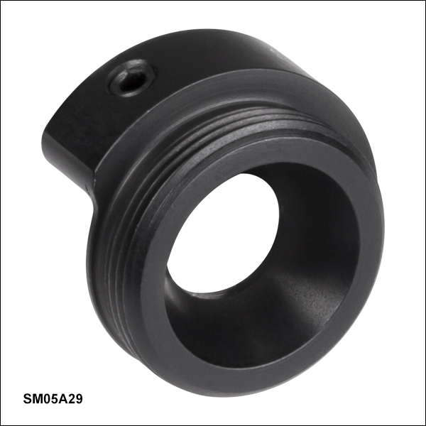 ズーム
ズーム
- 当社のコンパクト薄型フォトダイオードパワーセンサ対応
- SM05ネジ付きコンポーネントとの接続用
アダプタSM05A29は、2本の止めネジ(セットスクリュ)で当社のコンパクト薄型フォトダイオードセンサに取付けられます(止めネジには0.05インチ(1.3 mm)六角レンチが対応)。このアダプタを用いることで、SM05ネジの付いたファイバーアダプタ、光学フィルタ、 機構部品、光学素子などをコンパクト薄型フォトダイオードセンサに取付けることができます。
※パワーセンサ校正について - 当社のパワーセンサ校正は自動で行われており、測定と同時にセンサ内のメモリにある補正データを書き換えます(出力されるデータは校正前の感度と校正後の感度になります)。また、センサ面(NDフィルタ)が汚れ等で正常に感度測定ができないと判断された場合には、フィルタ交換(無償)してから校正される場合がございますので、ご了承ください。この場合は校正前の感度は測定できません。測定と校正を別々に実施する場合には、事前のご連絡が必要です。また、校正のみの場合とは金額および期間が異なりますのでご注意ください。
| Calibration Service Item # | Compatible Sensors |
|---|---|
| CAL-UVPD | S120VC |
| CAL-PD | S116C, S120C, S121C, S170C, S171C, S140C, S142C, S142CL, S150C, S151C, PM16-120, PM16 |
| CAL-UVPD2 | S130VC |
| CAL-PD2 | S130C, PM16-130, PM160 |
| CAL-IRPD | S122C, S144C, S145C, S145CL, S146C, S154C, S155C, PM16-122, PM16-144 |
| CAL-IRPD2 | S132C |
| CAL-MIRPD | S148C, S180C |
Thorlabs offers recalibration services for our photodiode optical power sensors. To ensure accurate measurements, we recommend recalibrating the sensors annually. Recalibration of a single-channel power and/or energy meter console or interface is included with the recalibration of a sensor at no additional cost. If you wish to calibrate one or more sensors with a dual-channel console, each sensor and console calibration service will need to be purchased individually. For more details on these recalibration services, please click the Documents (![]() ) icons below.
) icons below.
Refer to the table to the right for the appropriate calibration service Item # that corresponds to your power sensor.
Requesting a Calibration
Thorlabs provides two options for requesting a calibration:
- Complete the Returns Material Authorization (RMA) form. When completing the RMA form, please enter your name, contact information, the Part #, and the Serial # of each item being returned for calibration; in the Reason for Return field, select "I would like an item to be calibrated." All other fields are optional. Once the form has been submitted, a member of our RMA team will reach out to provide an RMA Number, return instructions, and to verify billing and payment information.
- Select the appropriate sensor calibration Item # below, enter the Part # and Serial # of the sensor that requires recalibration, and then Add to Cart. If you would like a console calibrated with your sensor, repeat this process for Item # CAL-PM1 or CAL-PM2 below, entering the console Item # and Serial #. A member of our RMA team will reach out to coordinate the return of the item(s) for calibration. Note that each console calibration Item # represents the cost of calibrating a console alone; if requesting a single-channel console calibration with a sensor calibration, the appropriate discount will be applied when your request is processed. Should you have other items in your cart, note that the calibration request will be split off from your order for RMA processing.
Please Note: To ensure your item being returned for calibration is routed appropriately once it arrives at our facility, please do not ship it prior to being provided an RMA Number and return instructions by a member of our team.
※パワーセンサ校正について - 当社のパワーセンサ校正は自動で行われており、測定と同時にセンサ内のメモリにある補正データを書き換えます(出力されるデータは校正前の感度と校正後の感度になります)。また、センサ面(NDフィルタ)が汚れ等で正常に感度測定ができないと判断された場合には、フィルタ交換(無償)してから校正される場合がございますので、ご了承ください。この場合は校正前の感度は測定できません。測定と校正を別々に実施する場合には、事前のご連絡が必要です。また、校正のみの場合とは金額および期間が異なりますのでご注意ください。
| Calibration Service Item # | Compatible Consoles & Interfaces |
|---|---|
| Single-Channel | |
| CAL-PM1 | PM100D, PM100A, PM400, PM100USB, PM101 Series, PM102 Series, PM103 Series |
| Dual-Channel | |
| CAL-PM2 | PM5020, Previous-Generation PM320E |
These recalibration services are for the power and/or energy meter electronics of our consoles and interfaces. To ensure accurate measurements, we recommend recalibrating annually. Recalibration of a single-channel console or interface is included with these sensor recalibration services at no additional cost. If you wish to calibrate one or more sensors with a dual-channel console, each sensor and console calibration service will need to be purchased individually. For more details on these recalibration services, please click the Documents (![]() ) icons below.
) icons below.
The table to the upper right lists the power and/or energy meter consoles and interfaces that can be calibrated using the CAL-PM1 and CAL-PM2 recalibration services.
Requesting a Calibration
Thorlabs provides two options for requesting a calibration:
- Complete the Returns Material Authorization (RMA) form. When completing the RMA form, please enter your name, contact information, the Part #, and the Serial # of each item being returned for calibration; in the Reason for Return field, select "I would like an item to be calibrated." All other fields are optional. Once the form has been submitted, a member of our RMA team will reach out to provide an RMA Number, return instructions, and to verify billing and payment information.
- Select the appropriate Item # below, enter the Part # and Serial # of the item that requires recalibration, and then Add to Cart. If you would like to calibrate one or more sensors with your console, repeat this process for the appropriate sensor recalibration service above, entering the console Item # and Serial #. A member of our RMA team will reach out to coordinate return of the item(s) for calibration. Note that each console calibration Item # represents the cost of calibrating a console alone; if requesting a single-channel console calibration with a sensor calibration, the appropriate discount will be applied when your request is processed. Should you have other items in your cart, note that the calibration request will be split off from your order for RMA processing.
Please Note: To ensure your item being returned for calibration is routed appropriately once it arrives at our facility, please do not ship it prior to being provided an RMA Number and return instructions by a member of our team.