アイリス、ポスト付き
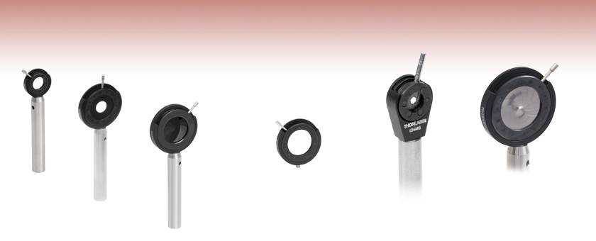
- Continuously Variable Irises with Sizes Ranging from Ø5.0 mm to Ø75.0 mm
- Black Anodized Aluminum Housing to Limit Reflections
- Black and Stainless Steel Blades Available
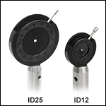
ID12
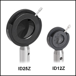
ID25
ID25Z
IDA25-P5
Pack of 5 with Threaded Stud
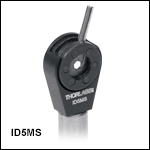
ID5MS
Mini-Series Iris
Enlarged to Show
Detail
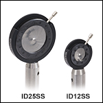
ID25SS
Enlarged to Show
Stainless Steel Leaves

Please Wait
Click to Enlarge
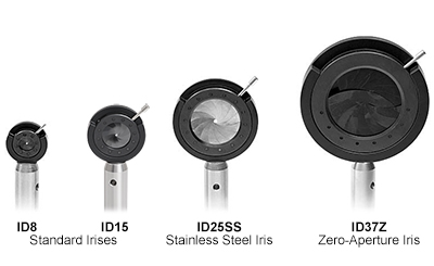
標準、ステンレススチール製、そしてゼロ開口アイリスの最小開口サイズの比較
| Iris Selection Guide |
|---|
| Post-Mountable Irises |
| Unmounted Irises |
| SM-Threaded Lever-Actuated Irises |
| SM-Threaded Ring-Actuated Irises |
| Cage System Irises |
特長
- 連続可変
- それぞれ筐体とポストが付属
- 一部のアイリスはポスト無しの5個入りセットでご提供
- 黒色アルマイト加工のアルミニウム製筐体が反射を制限
- 特注サイズにも対応可能
- ポスト無しアイリスもご用意
レバー作動による連続可変アイリスは、繰り返し滑らかな操作を行なうことができます。各絞り羽根は、黒色アルマイト加工のアルミニウム製筐体内で回転します。
下記のアイリス製品は、当社のミニシリーズ製品に対応するØ6 mmポストに取り付けられているミニシリーズポスト付きアイリス(ID5MS/M)と5個入りパックでご提供している標準のアイリス以外、すべて取り外し可能な長さ75 mmのØ12.7 mm(Ø1/2インチ)ポストに取り付けられています。また、ポストが付属せず底部にM4ネジが付いたアイリスは5個入りセットとしてご提供しています(IDAで始まる型番)。
当社ではこのページに掲載されているポスト付きアイリスのほかにも、SMネジ付きのレバー作動アイリスやリング作動アイリスをご用意しております。また、30 mm および 60 mmケージシステムとお使いいただけるケージシステム用アイリスもございます。
レーザービームをアライメントする方法
レーザを光学系に取り付ける場合、まず行うべきは、所望の光路設定をするためビームの水平度と方向を調整することです。このようにして設定されると、ビームをうまく迂回させてシステム内の光学素子を透過するように誘導できるだけでなく、システムのアライメントを調整することによって得られる結果が予測しやすくなり、再現性が高くなります。下記のセクションではそれぞれの方法について説明しています。
実験および機器についての「Insights-ヒント集」はこちらからご覧いただけます。
レーザービームのポインティング角度を水平にアライメントする方法
0:00 - はじめに
1:25 - レーザービームのポインティング角度を水平にし、アライメントする方法
4:09 - ビームを迂回させて任意の光路にアライメントする方法
Click to Enlarge
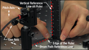
図2: ビームは、光学テーブルのタップ穴のラインに対して平行になるようアライメントすることができます。キネマティックマウントのヨー調整でビーム角度を調整し、ルーラをタップ穴のラインに沿ってスライドさせるときに、ビームの照射位置が横方向で動かないようにします。
Click to Enlarge
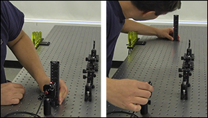
図1: :ビーム方向を光学テーブルの表面に対して水平にするには、レーザ用キネマティックマウントのピッチ調整を使用します(図2)。ビームがテーブル表面に対して平行になっている状態は、ビーム高がレーザ前面に近い位置(左)と遠い位置(右)でパワー測定値が同じであることを確認することで行います。
キネマティックマウントのピッチ(チップ)とヨー(ティルト)を調整することで、レーザ角度の微細な補正を行うことができます。この角度調整は、コリメート光を光学テーブル表面などの基準面に対して、あるいはテーブルのタップ穴のラインに沿ってなど基準面内の特定の方向に対してアライメントするときなどで行います。
マウントのアジャスタを使用する前に
まず、キネマティックマウントの各アジャスタを回して移動範囲の中央に移動させます。これにより調整範囲が足りなくなるリスクが少なくなります。また調整範囲の真ん中にアジャスタがあると、マウントのポインティング安定性が良くなります。
その後、レーザを支えるポストやポストホルダなどのオプトメカニクス部品を調整することで、レーザの高さ、位置、向きの粗調整を行います。 調整後はすべてのロックネジが締め付けられていることを確認してください。
ビームをテーブル表面に対して平行にする場合
レーザ光のレベル調整のため、アライメントツールを用いて、マウントのピッチアジャスタによる微細な調整を繰り返す必要があります。
まず光源から近い位置と遠い位置のビームの高さを測定します(図1)。2つの間の距離が長ければ長いほど、確度は高くなります。2つの位置のビーム高が一致するまで、キネマティックマウントのピッチを繰り返し調整します。
ピッチ調整により光源の高さも変わります。動画の例では、光源に近いビーム高は当初82 mmでしたが、最初のピッチ調整で83 mmに上がっています。
ビームを水平に調整した後は、レーザを支えるオプトメカニクス部品を所望の高さに調整します。または2つのステアリングミラーをレーザの後ろに置き、違う方法でアライメントすることもできます(詳細については同セクション内に記載されています)。ステアリングミラーは特に装置自体の角度調整が難しいレーザ装置のビームの高さと方向の調整に有用です。
ビームをタップ穴列に沿った向きに調整
ビームをテーブルのタップ穴列に対して平行にアライメントする場合もアライメントツールとマウントのヨーアジャスタの反復調整が必要になります。
アライメントツールにより、タップ穴列を基準線として、レーザ出力方向を調整できます。ルーラの底辺の端をタップ穴列に合わせて配置します(図2)。
テーブル上の基準線に対するビームの角度ズレは、ルーラに照射されるレーザースポット位置とルーラの垂直基準線の差を見ることで確認できます。取付けブラケットBHMA1を使用して水平置き型のルーラを取り付けることができます。
動画では、ルーラをタップ穴列に並行に移動し、レーザ照射位置をルーラーの1 mm単位の目盛の端に一致させるようにアライメントします。ルーラを基準線の遠い方の位置に移動させると、ルーラのビーム位置も水平方向に移動します。ルーラを遠い方の位置に配置した後、ビーム端が1 mm単位の目盛に一致するまでマウントのヨーを調整します。その後ルーラを光源の近くに移動させ、ビームの位置調整の結果を見ます。このプロセスは必要に応じて反復で行われています。
ビームを迂回させて任意の光路に沿ってアライメントする方法
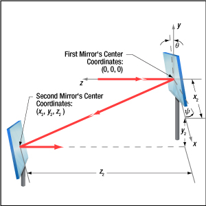
1つ目のステアリングミラーは、新しい光路上に配置された2つ目のミラーに向けてビームを反射します。2つ目のステアリングミラーは、新しい光路に沿うようにアライメントします。2つのステアリングミラーでレーザ光をアライメントする手順は、Walking the Beam(ビームの移動)として説明することがあり、その結果はFolded Beam Path(折りたたまれたビーム路)と呼ばれることがあります。上の動画の例では、ビームを新しい光路にアライメントするために2つのアイリスが使用されています。新しい光路は光学テーブル面に対して平行で、タップ穴列に沿っています。
Click to Enlarge
図3: 1つ目のミラーから反射されたビームは、x軸ならびにy軸まわりに、それぞれθおよびψ回転すれば、2つ目のミラーに入射します。どちらの角度も2つ目のミラーの中心位置(座標x2、y2、z2 )に影響を及ぼします。1つ目のミラーのx軸周りの回転は、マウントのピッチ(チップ)アクチュエータの移動範囲によって制限されますが、その移動範囲は、2つ目のミラーの位置と高さも制限します。
Click to Enlarge
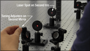
図5: 2つ目のキネマティックミラーマウントのアジャスタは、2つ目のアイリスにビームをアライメントするのに使用します。
Click to Enlarge
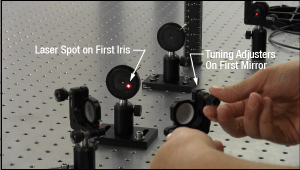
図4: 1つ目のキネマティックミラーマウントのアジャスタを調整して、1つ目のアイリスの開口部にレーザースポットを合わせています。
ミラーの高さの設定
1つ目のミラーの中心は、入射路の高さと一致させます。2つ目のミラーの中心は、新しい光路の高さに合わせてください。
アイリスのセットアップ
新しい光路はアイリスによって設定されます。動画では光路がテーブル面に対して水平となるよう、アイリスの高さが一致していることがご覧いただけます。マウント内のアイリスの高さはルーラかノギスを使用すると適度な精度で設定可能です。
アイリスが閉じているときの(小さな)開口部は、完全な中心位置にない場合があります。そのため、アイリスのビームの入力面をひっくり返すと、開口の位置がシフトする場合があります。アイリスのビーム入力面を決めたらセットアップから使用まで同じ面を使用することを推奨します。
コンポーネントの配置と粗調整
まず、両ミラーのアジャスタを回しながら移動範囲の中央に移動させます。1つ目のミラーは入射光路に配置し、2つ目のミラーは新しい光路上に配置します(図3)。1つ目のミラーのピッチ(チップ)アクチュエータの移動範囲がx周りのミラーの回転(θ )を制限するため、ミラー配置は1つ目のミラーのピッチ(チップ)アクチュエータの移動範囲によって限定されます。2つ目のミラーの位置(x2 、y2 、z2 )を選ぶときは、ピッチに加え、1つ目のミラーのヨー(ティルト)も考慮しなければなりません。2つのミラーは、1つ目のミラーの両アジャスタを移動範囲いっぱいに回さなくてすむよう配置してください。
新しい光路に2つ目のミラーを配置後、両方のアイリスを光路上に置いてください。1つ目のアイリスは2つ目のミラーの近くに、2つ目のアイリスは2つ目のミラーからできるだけ遠くに配置してください。
2つのミラーの高さはそのまま維持し、またヨーのアジャスタは触らずに1つ目のミラーを回転させて、光を2つ目のミラーに向けます。1つ目のミラーのピッチアジャスタを調整して、レーザースポットを2つ目のミラーの中心近くに移動させます。その後、2つ目のミラーを回転させて、ビームを新しい光路にある程度向けます。
最初に光路上に光を当て、その後、向きを調整します。
1つ目のミラーは、2つ目のミラー上にある新しい光路上の点に向けてビームをステアリングするために使用します。まず、1つ目のアイリスに当たるレーザースポットの位置を見ながら1つ目のミラーのアジャスタを調整します(図4)。アイリスの開口部の中心にレーザースポットが合えば最初のステップは終了です。
次に2つ目のミラーでビームをステアリングして、新しい光路とアライメントさせます。2つ目のミラーのアジャスタを調整して、レーザースポットを2つ目のアイリスの開口部に移動します(図5)。ピッチアジャスタがビームの高さを調整し、ヨーアジャスタがビームを横方向に移動します。2つ目のアイリスでレーザースポットが消えてしまう場合、2つ目のミラーのレーザースポットが新しい光路から離れています。
1つ目のミラーのアジャスタを調整しながら2つ目のミラー上のビーム位置を変え、1つ目のアイリスの開口部の中心にレーザースポットがあたるようにします。2つ目のミラーのアジャスタ調整を再開して、2つ目のアイリスの開口部にレーザースポットを向けます。これをレーザービームが両方のアイリスの中心を通るまで繰り返します(動画参照)。アジャスタのどれかが調整範囲の制限に近づいてしまったら、ミラーの1つ、あるいは両方の位置を変え、アライメント手順を繰り返してください。
ヨー軸のアジャスタが制限に近づいた場合、反射ビーム方向を記録しておき、ヨーアジャスタを調整範囲の中央に回転させます。反射ビーム方向が記録した位置になるようミラーマウントの向きを変えます。ミラーが回転できない場合、ビームが新しい光路にほぼ沿うよう1つあるいは両方のミラーの位置を変えます。ビームの向きが微細に調整できるまでこのアライメント手順を繰り返します。
ピッチ軸のアジャスタが制限に近づいた場合、2つのミラーの間の距離を長くするか、入射路と新しい光路の高さの差を小さくします。どちらの方法でもアライメント手順が繰り返された後、ピッチアジャスタが調整範囲の中心の近くに配置されます。
| Posted Comments: | |
Zheng Xiaoyan
(posted 2024-07-14 14:51:13.88) 我想知道不锈钢叶片光阑的损伤阈值是多少 jdelia
(posted 2024-07-16 08:53:02.0) Thank you for contacting Thorlabs. You asked: "I would like to know what the damage threshold is for stainless steel blade diaphragms." We unfortunately do not specify a damage threshold for our irises since it depends on several factors such as wavelength, iris opening, exposure duration, etc. If it helps, the maximum temperature that the blades can be heated would be around 400°C for the stainless steel irises. Takeya Unuma
(posted 2024-06-12 21:42:06.86) I hope you will produce arises with larger aperture diameters of 36 mm and 50 mm in this lineup.
I think Japanese customers like me prefer products without 12.7-mm-thick posts because they usually use 12-mm-thick posts. jdelia
(posted 2024-06-13 11:06:48.0) Thank you for contacting Thorlabs, and for providing this feedback. I have forwarded your request to our design engineers via our internal suggestion forum and have also reached out to you directly to discuss your application. Roger Holten
(posted 2023-01-30 11:55:54.79) It would be nice for beam alignment if the surface of the diaphragm was not black but say white and scattering so you can see the your beam on the iris more easily. Especially in the 50mm version as we would use them if available. ksosnowski
(posted 2023-01-31 01:42:42.0) Thanks for reaching out to Thorlabs. The diaphragms need to have certain mechanical properties and adding some coating like this to the diaphragms would prohibit smooth actuation of the mechanism. We do however had some alignment accessories like DG20-1500-H2-MD diffuser with through-hole as well as some diffuse coated targets like VRC4D1. While the VRCx series is designed to help convert lasers to visible range, even if the laser is already visible the diffuse surface could help in this scenario. Pascal Kiefer
(posted 2022-07-20 10:43:42.307) Dear Sir or Madam,
it would be perfect to have a post-mountable iris diaphragm with xy-control. With that, I could fine tune the lateral position of the hole with respect to my beam.
Do you have a solution for this?
Best regards,
Pascal Kiefer jdelia
(posted 2022-07-27 08:11:21.0) Thank you for contacting Thorlabs. We do not offer irises with built-in XY control, however we do offer SM-threaded irises. These can be combined with our threaded XY translation mounts. I have reached out to you directly to discuss potential solutions for you. Andrew Bayramian
(posted 2021-08-02 17:24:28.843) Noting that the inner iris diameter of this device:
https://www.thorlabs.com/thorproduct.cfm?partnumber=ID36
Is much larger than either of these:
https://www.thorlabs.com/thorproduct.cfm?partnumber=SM2D25
https://www.thorlabs.com/thorproduct.cfm?partnumber=SM2D25D#ad-image-0
Both ourselves and others would benefit from putting SM2 threads on the ID36, and replacing your SM2D25 and/or SM2D25D. YLohia
(posted 2021-08-05 01:22:11.0) Hello, thank you for your feedback. We will consider offering a redesigned version of the ID36 with SM2 threads in the future. Bruno Schmidt
(posted 2021-02-15 23:12:11.733) When you say the stainless steel leaves are for high power options, just how high are we talking? Do you have any data? YLohia
(posted 2021-02-16 11:48:11.0) Thank you for contacting Thorlabs. Unfortunately, we don't have a Damage Threshold spec for our iris diaphragms. It’s hard to specify the laser damage threshold in this case because it depends on several parameters such as wavelength, iris opening, exposure duration, etc. The maximum temperature that the blades can be heated would be around 250°C for the regular irises and around 400°C for the stainless steel versions. Marshall Scott
(posted 2019-06-19 11:15:04.483) I’m with Daaf. A version with diffusive or even fluorescent leafs would be amazing. Especially since the aperture is typically recessed into the mount where I can’t get a card. YLohia
(posted 2019-06-19 12:36:48.0) Hello, thank you for your feedback. I have posted your request to our internal product engineering forum for further consideration as a future product. campbellr
(posted 2019-02-19 11:15:34.293) The irises that are sold without a post are described as having a stud. Are the studs removable, leaving a tapped hole, so that I could mount them on a custom bracket using a screw?
Thanks,
Rob mmcclure
(posted 2019-02-20 07:46:32.0) Hello, thank you for contacting us. The studs featured on the IDAxx iris diaphragms are not removable, as the stud is designed to enable post mounting as well as to hold the iris firmly in place inside the aluminum housing. dan.reynolds
(posted 2017-03-17 15:42:56.133) I recently bought a ID75Z/M only to find that, somewhat annoyingly, the iris diaphragm system was too thick to act as an adjustable pinhole in the focal plane of my optical system. Before purchasing the ID36/M, could you tell me how thick its closed diaphragm is? It also might be worth mentioning the thickness of the zero-aperture irises somewhere on this page swick
(posted 2017-03-21 04:54:14.0) This is a response from Sebastian at Thorlabs. Thank you for the feedback.
The Zero Aperture Iris Diaphragms are not designed to be used as an adjustable pinhole. When the aperture gets smaller, it also becomes slightly elliptical due to the design of the iris.
Please note ID36/M is not a Zero Aperture Diaphragm, however, the thickness when diameter of the aperture is minimal (Ø1.3mm) is 0.41mm. srtweezer
(posted 2016-09-20 22:08:30.743) It would be useful to have irises whose height are exactly 0.5" to use as a reference for setting up the height of the laser beam. swick
(posted 2016-09-21 04:11:31.0) This is a response from Sebastian at Thorlabs: Thank you very much for your feedback.
We will evaluate if we can offer this as a special item.
I will contact you directly regarding customized irises. cacao23
(posted 2016-05-23 18:13:49.713) Dear,
I have a question.
Is that iris makes back beam?? except for center hole. shallwig
(posted 2016-05-25 03:36:14.0) This is a response from Stefan at Thorlabs. Thank you for your inquiry. The housing of the iris diaphragms are made from anodized aluminum to limit reflections. The leaves are made either from black spring steel or from Stainless Steel with different reflection properties. I have contacted you directly to check your application in detail. popei
(posted 2016-01-27 11:50:59.34) The height of the post supplied with the iris is too large for our needs. It would be useful if one could purchase the iris without the post. shallwig
(posted 2016-01-28 03:31:18.0) This is a response from Stefan at Thorlabs. Thank you very much for your inquiry. We offer these iris without post as special. I will contact you directly to check for which Iris you need a quote and if you have any further questions. daaf.sandkuijl
(posted 2015-09-01 06:50:25.75) It would be great to have an iris with matte white/light gray leaves instead of shiny and dark gray, for alignment purposes. In fact if that were available it would be the only type of iris I would use. shallwig
(posted 2015-09-02 05:18:04.0) This is a response from Stefan at Thorlabs. Thank you very much for your inquiry. At the moment we can only offer our post mounted Iris diaphragms with black spring steel leaves and stainless steel leaves. I will contact you directly to check if we can offer a special with different leaves. sfeldman
(posted 2014-01-06 13:52:09.18) The solid works model has a 2" post, while the overview says its a 3" post. Which is correct? And is it possible to get a 2" post instead of a 3"? tschalk
(posted 2014-01-07 07:37:15.0) This is a response from Thomas at Thorlabs. Thank you very much for your inquiry. The solid work files should contain a 3" post and we will modify the files. Thank you for pointing this out. The posts can be easily removed from the iris and, if an additional 2" post (part number TR2) is purchased, this one can be attached. This would be the easiest way to get an iris with 2" post. jlow
(posted 2013-01-24 11:56:53.857) Response from Jeremy at Thorlabs: Thank you very much for your feedback. We will look into this possibility. In the meantime, we could offer the iris without the optical post. You could then put the iris on the graduated post. Please contact our Tech Support group at techsupport@thorlabs.com if you would like to get a quote on the iris without a post. kevlarp
(posted 2013-01-23 16:31:21.23) It would be very helpful if mounted irises were available with your graduated posts (TR3E, for example). I often need irises to be at the exact same height, and having the graduated marks on the post that comes with the iris is helpful. bdada
(posted 2011-09-26 20:12:00.0) Response from Buki at Thorlabs:
Thank you for your feedback. I have passed on your suggestion to our design team. In the meantime, please review our selection of alignment disks to see if any may be suitable for your application.
http://www.thorlabs.com/NewGroupPage9.cfm?ObjectGroup_ID=3201
I have contacted you directly to assist you in selecting one of our alignment disks that may work for you. sshosseini
(posted 2011-09-23 04:14:07.0) It would be very helpful if you could make a product that can clip to the back of the irises in white color and a cross in the center of the iris. I use papers and tapes to do so for alignment purposes at dark but I also need to take the paper out and put it back in several times to check the alignment and every time I have to put it back it takes some time and I need to have more light which ruins my dark vision.
~Sona apalmentieri
(posted 2009-12-15 21:46:43.0) A response from Adam at Thorlabs: We can supply these solid parts and will send you an email with these files attached. noam
(posted 2009-12-09 10:19:34.0) can you please send me a solid part of ID15? |

| Item # | Aperturea | # of Leaves | O.D. / Thickness |
|---|---|---|---|
| ID8 (ID8/M) | Ø0.8 to Ø8.0 mm | 8 | 0.84" / 0.24" (21.4 mm / 6.0 mm) |
| ID12 (ID12/M) | Ø1.0 to Ø12.0 mm | 10 | 1.04" / 0.23" (26.4 mm / 5.8 mm) |
| ID15 (ID15/M) | Ø1.2 to Ø15.0 mm | 12 | 1.20" / 0.26" (30.6 mm / 6.5 mm) |
| ID20 (ID20/M) | Ø1.2 to Ø20.0 mm | 12 | 1.44" / 0.28" (36.6 mm / 7.0 mm) |
| ID25 (ID25/M) | Ø1.4 to Ø25.0 mm | 14 | 1.72" / 0.26" (43.7 mm / 6.6 mm) |
| ID36 (ID36/M) | Ø1.9 to Ø36.0 mm | 16 | 2.24" / 0.28 " (56.9 mm / 7.1 mm) |
| ID50 (ID50/M) | Ø2.5 to Ø50.0 mm | 16 | 3.12" / 0.35" (79.4 mm / 8.9 mm) |
- レバー作動で連続可変のアイリス
- 黒色バネ鋼製絞り羽根
- 黒色アルマイト加工アルミニウム製筐体
- 長さ75 mmのØ12.7 mmポストTR75/Mに取付け済み

| Item # | Aperturea | # of Leaves | O.D. / Thickness |
|---|---|---|---|
| IDA12-P5 (IDA12/M-P5) | Ø1.0 to Ø12.0 mm | 10 | 1.04" / 0.23" (26.4 mm / 5.8 mm) |
| IDA15-P5 (IDA15/M-P5) | Ø1.2 to Ø15.0 mm | 12 | 1.20" / 0.26" (30.6 mm / 6.5 mm) |
| IDA20-P5 (IDA20/M-P5) | Ø1.2 to Ø20.0 mm | 12 | 1.44" / 0.28" (36.6 mm / 7.2 mm) |
| IDA25-P5 (IDA25/M-P5) | Ø1.4 to Ø25.0 mm | 14 | 1.72" / 0.26" (43.7 mm / 6.6 mm) |
- レバー作動で連続可変のアイリス
- 黒色バネ鋼製絞り羽根
- 黒色アルマイト加工アルミニウム製筐体
- ポスト取付け用に底部にM4止めネジ
- 5個入りセット
このアイリスにはM4止めネジが付いていますが、ポストは付属しておりません。 |

| Item # | Aperturea | # of Leaves | O.D. / Thickness |
|---|---|---|---|
| ID12Z (ID12Z/M) | Ø0.0 mm to Ø12.0 mm | 10 | 1.09" / 0.32" (27.6 mm / 8 mm) |
| ID25Z (ID25Z/M) | Ø0.0 mm to Ø25.0 mm | 14 | 1.76" / 0.32" (44.6 mm / 8 mm) |
| ID37Z (ID37Z/M) | Ø0.0 mm to Ø37.0 mm | 16 | 2.56" / 0.41" (65.0 / 10.5 mm) |
| ID50Z (ID50Z/M) | Ø0.0 mm to Ø50.0 mm | 16 | 3.35" / 0.49" (85.0 / 12.5 mm) |
| ID75Z (ID75Z/M) | Ø0.0 mm to Ø75.0 mm | 20 | 4.53" / 0.51" (115 / 13 mm) |
- 最小開口:ゼロ
- レバー作動で連続可変のアイリス
- 黒色バネ鋼製絞り羽根
- 黒色アルマイト加工アルミニウム製筐体
- 絞り羽根の2層構造によりゼロ開口を実現
- 長さ75 mmのØ12.7 mmポストTR75/Mに取付け済み
レバーを閉の位置にしたときに、絞り羽根が1層のアイリスでは開口径がゼロにはなりませんが、こちらのアイリスの開口径はゼロになり、完全に閉じた状態になります。当社のゼロ開口アイリスは、隣接する面に絞り羽根を2組使用することにより、開口部を完全に閉じられます。アイリスの設計上、開口部が小さくなると若干楕円形になりますのでご注意ください。

| Item # | Aperturea | # of Leaves | O.D. / Thickness |
|---|---|---|---|
| ID12SS (ID2SS/M) | Ø1.0 to Ø12.0 mm | 10 | 1.04" / 0.23" (26.4 mm / 5.8 mm) |
| ID25SS (ID25SS/M) | Ø1.4 to Ø25.0 mm | 14 | 1.72" / 0.26" (43.7 mm / 6.6 mm) |
- 高出力用途向けのステンレス製絞り羽根
- レバー作動で連続可変のアイリス
- 黒色アルマイト加工アルミニウム製筐体
- 長さ75 mmのØ12.7 mmポストTR75/Mに取付け済み
このアイリスは、磁性ステンレススチール製です。硬度が高いため、従来の非磁性ステンレススチール製アイリスより耐久性に優れた製品です。

| Item # | Aperture | # of Leaves | O.D./Thickness |
|---|---|---|---|
| ID5MS (ID5MS/M) | Ø0.6 to Ø5.0 mm | 6 | 0.44" / 0.19" (11.2 mm / 4.8 mm) |
- レバー作動で連続可変のアイリス
- 黒色バネ鋼製絞り羽根
- 黒色アルマイト加工アルミニウム製筐体
- Ø6 mm、長さ38 mmのポスト上に取付け済み
本製品は、当社のミニシリーズのポスト製品と使用できるように設計されていて、限られた空間での用途に適しています。当社のミニシリーズ製品では、小型セットアップあるいは組み込み用途(OEM用途)向けのオプトメカニクスアセンブリ用の部品を多数ご提供しております。ID5MS/Mの詳細については、製品ページをご覧ください。
 Products Home


 ズーム
ズーム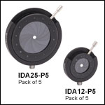
 ポスト付きアイリス