 Products Home
NanoMaxシリーズ3軸フレクシャーステージ、コントローラー付き
- 3-Axis Piezo Flexure Stage with Compatible Controller
- 4 mm of Manual Travel for Each Axis
- Piezo Actuators Provide 20 µm of High-Resolution Displacement
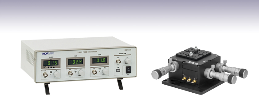
Three-Channel Piezo Controller
MDT630B
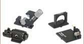
Three-Axis Flexure Stage with
Differential Micrometers Installed


Please Wait

Click for Details
コントローラMDT693Bの前面パネル

Click to Enlarge
粗調整および微調整機能付きマイクロメータDRV3
このセットには、3軸NanoMaxフレクシャーステージMAX302/M、3つの差動マイクロメータDRV3、および3チャンネルピエゾコントローラMDT693Bが含まれており、それぞれを個別にご購入いただくよりもお得になっています。 セットでご利用いただくことにより、NanoMaxステージMAX302/Mの位置をX、Y、Z軸に沿ってサブミクロン分解能でローカル操作およびリモート操作することが可能です。 それぞれの軸の最大移動範囲は4 mmです。 差動マイクロメータDRV3により、4 mmの粗動と300 µmの微動が可能で、微動時の分解能は100 nm(計算値)です。 内蔵のピエゾ素子により、20 µmの微動を実現します。
このセットには3本のSMCケーブルと3つのSMC-BNCアダプタ(MDC40211)、およびAC電源コード(日本国内用)が付属しています。
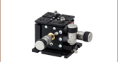
3軸NanoMaxフレクシャーステージMAX302/M
サブミクロンの分解能が要求されるアライメント向けに設計されています。特許取得済みのMAX302/Mのフレクシャ設計により、低いクロストークと高い安定性、そして長期にわたる信頼性を備えています。 また、このステージには、当社の全てのフレクシャーステージ用アクセサリが取付け可能です。 通常の多軸積層ステージでは、ベースに接続されていない2軸のどちらかに触れると、アセンブリ内で不要な動きが生じる場合があります。 NanoMaxシリーズのステージでは、全ての軸がステージのベースに直結するので、このような悪影響が抑えられます。 詳しい内容については、MAX302/Mの製品紹介ページをご参照ください。
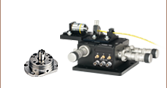
差動マイクロメータDRV3
DRV3には、粗調整および微調整用に2つの大径のノブが付いています。 粗調整ノブでは4 mmの移動が可能で1回転につき500 µm、微調整ノブでは300 µmの移動が可能で1回転につき50 µm移動します。 このアクチュエータの分解能は100 nmです。 微調整ノブをゴムグリップで覆うことにより、僅かな調整を行う際の熱伝導が減り、安定性が高まっています。 詳しい内容については、DRV3の製品紹介ページをご参照ください。
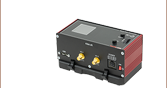
3軸開ループピエゾコントローラMDT693B
ピエゾコントローラMDT693Bには、3つの出力チャンネルがあり、それらは精密、低ノイズで、単独操作が可能です。これによりMAX302/Mは最大75 Vまでの電圧で操作が可能です。制御は、前面パネルの回転式つまみを回すか、外部信号をBNCまたはUSB2.0を経由して送ることで行うことができます。 詳しい内容については、MDT693Bの製品紹介ページをご参照ください。
3軸フレクシャーステージ MAX302/M
| Item # | MAX302(/M) |
|---|---|
| General Specifications | |
| Travel per Axis | 4 mm |
| Load Capacity | < 1.54 lbs (<0.7 kg) Recommended 2.2 lbs (1 kg) Max |
| Thermal Stability | 1 µm/°C |
| Deck Height | 2.46" (62.5 mm) |
| Optical Axis Height | 2.95" (75 mm) |
| Weight | 1.65 lbs (0.75 kg) |
| Piezo Specifications | |
| Piezo Voltage Range | 0 - 75 V |
| Piezo Travel Range | 20 µm +0.2 µm / -0.0µm |
| Piezo Bidirectional Repeatability | 0.2 µm |
| Piezo Absolute On-Axis Accuracy | 1.0 µm |
| Resonant Frequency | 375 Hz (No Load) 200 Hz (275 g Load) 150 Hz (575 g Load) |
| Arcuate Cross Talk | |||
|---|---|---|---|
| As a Function of X-Axis Positiona | As a Function of Z-Axis Positionb | ||
| X-Axis Position | Arcuate Motion in Z-Axis | Z-Axis Position | Arcuate Motion in X-Axis |
| 0.0 mm | 80.0 µm | 0.0 mm | 57.1 µm |
| 0.5 mm | 45.0 µm | 0.5 mm | 32.1 µm |
| 1.0 mm | 20.0 µm | 1.0 mm | 14.3 µm |
| 1.5 mm | 5.0 µm | 1.5 mm | 3.6 µm |
| 2.0 mm | 0.0 µm | 2.0 mm | 0.0 µm |
| 2.5 mm | 5.0 µm | 2.5 mm | 3.6 µm |
| 3.0 mm | 20.0 µm | 3.0 mm | 14.3 µm |
| 3.5 mm | 45.0 µm | 3.5 mm | 32.1 µm |
| 4.0 mm | 80.0 µm | 4.0 mm | 57.1 µm |
差動マイクロメータ DRV3
| Item # | DRV3 |
|---|---|
| Travel Range | Coarse: 4 mm (0.16") When Used with MAX302c Fine: 300 µm |
| Translation per Revolution | Coarse: 500 µm/rev Fine: 50 µm/rev |
| Resolution | Fine: 100 nm (Calculated) |
3軸ピエゾコントローラMDT693B
| Item # | MDT693B |
|---|---|
| Output Specifications | |
| Number of Channels | 3 |
| Connectors | BNC (One BNC-to-SMC Adapter per Channel Included) |
| Output Voltage | 0 - 75 V, 0 - 100 V, or 0 - 150 V (Selected by Switch on Rear) |
| Output Voltage Resolution When Using Knobs | 1.1 mV (for 75 V Output Voltage Setting) 1.5 mV (for 100 V Output Voltage Setting) 2.2 mV (for 150 V Output Voltage Setting) |
| Output Current (Max) | 60 mA |
| Output Noised | 1.5 mV (RMS) ~9.9 mV (Peak-to-Peak) |
| Output Impedance (Max) | 150 Ω, 1.0 nF |
| Load Impedancee (Min) | 2.5 kΩ |
| Bandwidth (-3 dB) | 9 kHz (No Load, Small Signal) 8.5 kHz (No Load, 150 Vpp)f 200 Hz (1.4 µF Piezo, 150 Vpp)f |
| Bandwidth Stability (-3 dB) | < 0.01% Over 5 Hours |
| External Control through BNC | |
| Input Voltage | 0 - 10 V |
| Input Impedance | 10 kΩ |
| Input Gain | 7.5 V/V ± 5% (for 75 V Output Voltage Setting) 10 V/V ± 5% (for 100 V Output Voltage Setting) 15 V/V ± 5% (for 150 V Output Voltage Setting) |
| Output Voltage Resolution When Using BNC | Limited by Noise of External Voltage Source |
| Scan Trim Gain Adjustment | 80% to 120% of Sum of Master Scan External Voltage and Offset from Rotary Adjustment Knob |
| External Control through Command Line | |
| Physical Interface | Female Type B USB 2.0 Connector |
| Digital-to-Analog Resolution | 16-Bit, 2.75 mV |
| Analog-to-Digital Resolution | 16-Bit, 3.0 mV |
| Physical Specifications | |
| Display Type | 7-Segment LED with Four Digits |
| Display Resolution | 0.1 V |
| Enclosure Size | 12.18" × 4.15" × 8.55" (309.4 mm × 105.5 mm × 217.1 mm) |
| Weight | 3.02 kg (6.65 lbs) |
| Operating Temperature | 10 to 40 °C |
| Power Specifications | |
| Input Voltage | 100 - 240 VAC |
| Input Frequency | 50 - 60 Hz |
| Input Power (Max) | 60 VA |
| Fuse Type | IEC60127-2/3 (250 VA, Slow Blow, Type "T") |
| Fuse Dimensions | 5 mm x 20 mm |
| Fuse Rating | 600 mA |
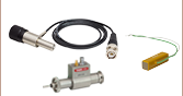
3軸フレクシャーステージMAX302/M
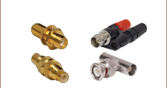
SMCオス型
入力電圧: 0~75 V
3チャンネル型ピエゾコントローラMDT693B
ピエゾ出力用端子
BNCメス型
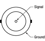
出力電圧: 0~150 V
最大出力インピーダンス: 150 Ω、1.0 nF
外部電圧制御用端子
BNCメス型
入力電圧: 0~10 V
入力インピーダンス: 10 kΩ
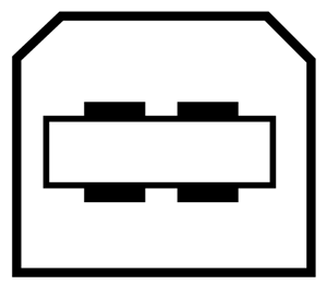
外部PC制御用端子
USB B型メス
ピエゾアクチュエータの帯域幅に関するチュートリアル
多くの高速用途では、ピエゾ素子の形状変化する速度を知ることが必須となります。 ピエゾコントローラとピエゾ積層の帯域幅は、下記の数値がわかることで、計算で求められるようになります。
- コントローラが供給可能な最大電流量。下記で例としてとりあげられているBPCシリーズのピエゾコントローラでは、この数値は0.5 Aです。
- ピエゾ素子の負荷容量。容量が大きいほどシステムは遅くなります。
- 信号振幅の最適値(V)。この振幅がピエゾ素子の伸長寸法を決定します。
- ドライバの最大帯域幅。この数値は駆動負荷に依存しません。
出力コンデンサを駆動する際には、帯電と放電にそれぞれ電流が必要です。 帯電電荷の変化dV/dtはスルーレートと呼ばれています。 静電容量が大きいほど、必要とされる電流量は大きくなります。
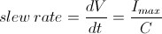
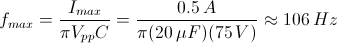
例えば100 µmのピエゾ積層において静電容量が20 µFで、最大電流量が0.5 AのBPCシリーズピエゾコントローラで駆動されるとき、スルーレートは下記の数式で求められます。
したがって電圧が瞬間的に0 V から75 Vに変化するとき、出力電圧が75 Vに達するには3 msかかります。
注記: これらの計算式においては、ドライバの最大帯域幅は計算によって得られる帯域幅よりもずっと大きな値であり、ドライバの帯域幅は制限要因とならないことを前提としています。 なおこれらの数式が、開ループシステムにしか適用できない点にご注意ください。 閉ループモードでは、フィードバックループの応答の遅延がさらに帯域幅を制限します。
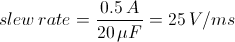
正弦波信号
システムの帯域幅は、通常は所定の振幅の正弦信号に対するシステムの応答により規定します。 正弦信号のピーク振幅がA、ピーク‐ピーク電圧がVpp、そして周波数がfの条件で駆動されているピエゾ素子については、以下の数式が成立します。
右の図は、時間の経過とともに変化する電圧を表しています。 スルーレートの最大値、または電圧の最大の変化は、t = 2nπ, (n=0, 1, 2,...)が成立する時点となり、右図では点 aで示されています。

上記の数式から下記が導出できます。

それゆえに下記が成立します。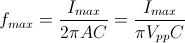
上記の例では最大電圧(75 V)での帯域幅は下記の値になることがわかります。
 .
.
ピエゾが小さく、静電容量が1/10になると、結果は10倍向上して約1060 Hzとなります。 また、積層が100 µmのままであっても、ピーク‐ピーク電圧が7.5 V(10% の最大振幅値)であれば、結果は同様に10倍向上して約1060 Hzとなります。
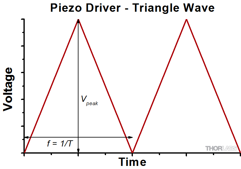
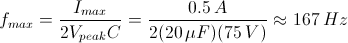
三角波信号
ピエゾアクチュエータが三角波で駆動される場合、最大電圧がVpeakで、最小電圧が 0の時、スルーレートは勾配もしくは下記に等しくなります。
![]() .
.
あるいはf = 1/Tであるので、下記が導出できます。
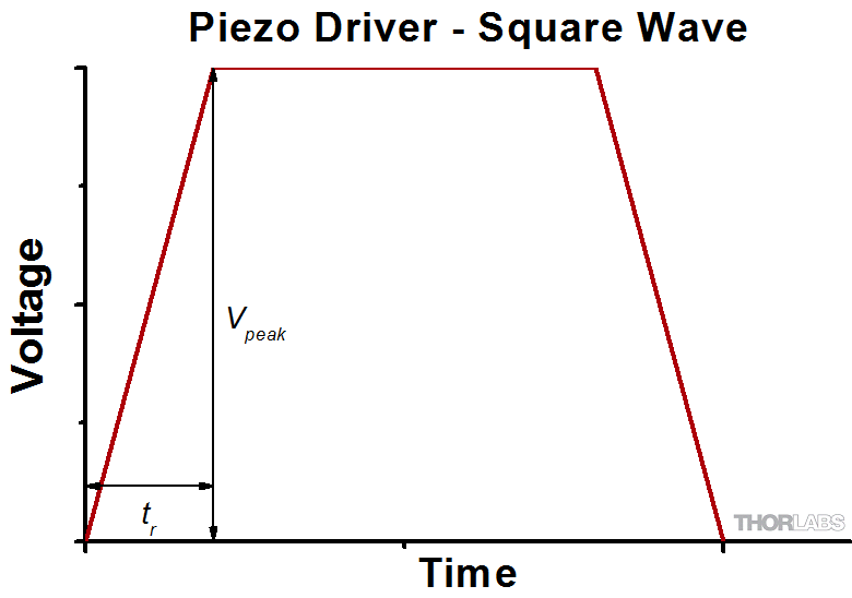
矩形波信号
ピエゾアクチュエータが矩形波で駆動される場合、最大電圧がVpeakで、最小電圧が 0の時、スルーレートが最小の立ち上がりと立ち下がりの数値を制限します。この条件では、信号の立ち上がりまたは立ち下がりの途中では、スルーレートは勾配に等しくなります。 trが最小立ち上がり時間であるとき、下記の数式が成り立ちます。
この式により、下記の数式が成立することもわかります。
 .
.
ピエゾの動作や理論についてはピエゾ素子のチュートリアルをご参照ください。
ピエゾコントローラ用ソフトウェア
バージョン2.4.2
MDT693B制御用GUI&ドライバ、およびサードパーティの開発用SDK付きのソフトウェアパッケージ。
シリアルコマンドを使用した外部制御
ピエゾコントローラMDT693Bの3つの出力チャンネルはUSB経由のシリアルコマンドを用いて調節することもできます。コマンドの種類はマニュアルの第7章に記載されています。 コマンドにはチャンネル毎に電圧の読み出しや設定を行う機能、固定ステップでの制御電圧の増減機能、ならびにマスタースキャンモードの切り替え機能が含まれます。
互換性
ピエゾコントローラMDT693Bは、旧世代製品のMDT693Aの制御用ソフトウェアならびにシリアルコマンドに対応します。
バージョン2のソフトウェアを使用する場合、バージョン1.09以降のファームウェアが必要です。ファームウェアは左の「Software」ボタンのリンク先ページでアップデートが可能です。
| Posted Comments: | |
Mark Martino
(posted 2024-02-02 10:05:28.42) Hello Thorlabs,
I'm interested in a PZT stage that can cover roughly 200 microns total travel with a resolution of roughly 100nm. Do I need to actuate this stage with a ~100V or higher PZT controller/amplifier/driver is required? Do you have suggestions for PZT stages for phase shifting our interferometer (midwave at 10.6 microns)?
Thanks!
Mark cdolbashian
(posted 2024-02-16 09:20:58.0) Thank you for reaching out to us with this inquiry. For small, qualitative, steps like this a piezo actuator is certainly the best approach here. I have reached out to you directly to discuss your application. Moritz Cavigelli
(posted 2023-09-05 11:11:53.74) I cannot get the manual as a pdf version, as the link just forwards me to a blank page. Could you please provide me with the corresponding manual?
Thanks! ksosnowski
(posted 2023-09-07 02:41:07.0) Hello Moritz, thanks for reaching out to Thorlabs. The MDT630A kit we used to sell included our MDT693A Piezo Driver, MAX302 Stage, and DRV3 differential micrometer. Each of these devices have their own manual which are available on our website. We currently offer a newer piezo driver MDT693B as well in our new kit part# MDT630B using the same stage and actuator. HANG CHEN
(posted 2021-06-12 17:00:37.117) Hi,
I am wondering what the relationship between the applied voltage and the travel displacement. Are they linearly dependent? Thanks. cdolbashian
(posted 2021-06-22 03:44:53.0) Thank you for reaching out to us at Thorlabs. Piezo elements have a nonlinear relationship with the applied voltage, especially for bare piezos. Additionally they will exhibit electrical hysteresis: the Voltage-to-Displacement relationship will differ as a function of the previous Voltage setpoint. More information can be found in our short tutorial on piezos on the "technical resources" section of our "Products" menu. Giuseppe Vicidomini
(posted 2020-11-09 15:35:27.84) Dear Sir or Madam,
I am using the MDT630B/M 3-Axis NanoMax stages but I am not able anymore to control the z-axis. In particular, by turning the know I can only reach the value 6.2 V. By changing the cables, i.e., using the y-output to control the z-axis of the stage, I had a similar problem. While using the z-output for the y-axis I do not have a problem. Reading the manual I have the impression that the z-axis enters a sort of protection modality, and the controller attenuates the output. Do you have any suggestions to solve this problem. YLohia
(posted 2020-12-29 03:09:03.0) Hello, thank you for contacting Thorlabs. We reached out to you directly a while ago to gather more details to help troubleshoot -- please reply to us at europe@thorlabs.com if you still have this issue. Are you using an external signal, or are you using the controller in stand-alone operation? Are you still able to adjust the z-axis properly using the manual adjuster? Can you please check that all manual adjusters are properly inserted in the stage? They must be in contant with the stage for the piezos to move. Would you be able to view the output of the MDT630B/M controller on an oscilloscope to verify that the controller is able to output the right voltage? `mbirowosuto
(posted 2016-06-14 22:34:47.77) Dear Sir,
We need a software for this Nanomax 300 product (MDT6938). We purchase it but we didnot receive the software. Serial Number is 150424175409.
Thanks and looking forward,
Best regards,
Dr. Danang Birowosuto
Nanyang Technological University besembeson
(posted 2016-06-15 05:32:57.0) Response from Bweh at Thorlabs USA: At the bottom of the overview on this page, we have a link to the "full MDT693B presentation" that also includes the software. We will make the software link more visible. Here is the link to the page with the software for you to download: http://www.thorlabs.com/newgrouppage9.cfm?objectgroup_id=1191 julien.paparone
(posted 2014-04-09 05:05:37.36) Hello,
I'm currently trying to interface my MDT693B with my computer (win7 pro x64 sp1) via labview. The CD application is unable to install the drivers, and the software provided on the website being out-of-date, I can't use the product as it is meant to. Have you been experiencing this problem so far, and if so, how did you manage to fix it ?
Yours,
Julien Paparone cdaly
(posted 2014-04-09 05:31:29.0) Response from Chris at Thorlabs: To install the drivers from the CD, you will need to have administrative privileges on the computer. If you are not an administrator, you can also browse the CD for the file “CD-Starter2.exe” in the root of the CD. Right click the file and choose the “Run as administrator” option from the menu, this should solve the issue, but we will contact you directly to provide any additional support. snaghizadeh
(posted 2014-03-02 19:27:46.813) Dear Sir/Madam,
I am contacting you from Koç university, Istanbul, Turkey.
We are using your MDT693A piezo controller. I am trying to write a LabView code, in which I wish to find the max output from our sample at each (x,y) coordinate pair.
Please do me a favor and assist me in understanding the following questions.
1)I read through manuals, however, I could not find relationship between voltage and displacement.
I mean to have minimum displacement of 20 nm, how much should I change the voltage? Does this amount depend on different voltage scales (75 ,100)?
2) What is the minimum voltage step(resolution)?
3)Does the displacement happen in both positive and negative X, Y, and Z directions? If so, what voltage range cause movement in negative directions?
Many thanks,
Solmaz cdaly
(posted 2014-03-06 04:06:26.0) 1) The controller is an open loop controller. It simply outputs a voltage. There is no feedback capability in an open loop system to display something like position. If you were to assume a linear response form your piezo, you would get the given displacement you want by the voltage range and divide by the range in the same distance units as your displacement range. V(x)=VMax*X/Range. We cannot guarantee this will work as piezo devices are not strictly linear.
2) The display resolution of the controller is +/-0.1V, though the actual resolution, when using a software interface an analog input to drive the voltage would be 2.75mV.
3) This depends on your piezo device. Some piezos cannot handle a reverse bias and can only be used in the positive voltage range to extend the piezo. Thorlabs
(posted 2010-10-06 11:32:01.0) Reponse from Javier at Thorlabs to kl_mun: we currently do not offer 25 mm travel stages fit with piezo control for fine adjustment. I will contact you directly to discuss your application requirements. kl_mun
(posted 2010-10-06 06:00:30.0) Can we upgrade the MDT630A/M with a 25mm of coarse travel instead of 4mm?
Thanks. |
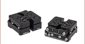
多軸ステージセレクションガイド

Click to Enlarge
上の使用例では、NanoMax3軸フレクシャーステージを6軸ステージの前に置き、高さ調整アダプタAMA554(/M)を使用してデッキ高112.5 mmに整合させています。
3軸ステージ
当社では3種類の3軸ステージをご用意しております。フレクシャーステージNanoMax、コンパクトフレクシャーステージMicroBlock、長距離移動ステージRollerBlockです。どのステージも公称デッキ高は62.5 mmです。3軸ステージのNanoMaxのラインナップには、内蔵型の閉ループまたは開ループのピエゾアクチュエータのほかに、ステッピングモータや差動アクチュエータ、その他のピエゾアクチュエータなどのモジュール型駆動製品をご用意しております。MicroBlockステージには、差動マイクロメー ターアクチュエータや精密つまみネジが付いていますが、それらのアクチュエータは取り外しができません。RollerBlockステージのアクチュエータ は、Ø9.5 mmの取付けバレルが付いたアクチュエータであれば交換可能です。
4軸ならびに5軸ステージ
当社の4軸ならびに5軸ステージは、3軸ならびに6軸の高性能アライメントステージと比較した場合、導波路や複雑な光学素子の静的な位置決めにより適しています。5軸ステージの公称高さは、62.5 mmまたは112.5 mmになります。3軸または4軸ステージの高さを5軸MicroBlockあるいは6軸NanoMaxステージに合わせて112.5 mmに上げたい場合には、ライザーブロック(高さ調整ブロック)AMA554(/M)をご使用いただけます。
6軸ステージ
当社のNanoMax 6軸ナノポジショナは複雑な多軸ポジショニングシステムに適しており、公称デッキ高は112.5 mmです。こちらのステージは共通の回転中心を有しています。また特許取得済みの平行フレクシャ設計により、すべてのアクチュエータがベースに直接結合し、システム内の不要な動きを最小限に抑えています。ピエゾ素子はオプションで閉ループでも開ループでも組み込めます。モジュール型設計のためアクチュ エータを交換することができ、すべての軸で手動式、またはピエゾ素子による電動式にすることが可能です。アクチュエータが付属しないタイプについては、右手系、左手系のどちらの構成でもご用意しております。 3軸ステージの高さを112.5 mmに上げたい場合には、右の写真のように高さ調整アダプタAMA554(/M)のご使用をお勧めいたします。
当社の多軸ステージのラインナップならびに比較は下の表でご覧ください。
3軸ステージ
| Item # | MAX313D | MAX312D | MAX311D | MAX383 | MAX381 | MAX303 | MAX302 | MAX301 | MBT602 | MBT616D | RB13M | RBL13D | ||||||||
|---|---|---|---|---|---|---|---|---|---|---|---|---|---|---|---|---|---|---|---|---|
| Stage Type | NanoMax Flexure Stages | MicroBlock Compact Flexure Stages | RollerBlock Long Travel Stages | |||||||||||||||||
| Included Drives | DRV3 Differential Micrometers | DRV208 Stepper Motor Actuators | N/A | Fine Thread Thumbscrews | Differential Micrometers | 148-801ST Micrometer Drives | DRV304 Differential Micrometers | |||||||||||||
| Built-in Piezos | N/A | Open Loop | Closed Loop | N/A | Closed Loop | N/A | Open Loop | Closed Loop | N/A | N/A | ||||||||||
| Travel (X, Y, Z) | 4 mm (0.16") | 13 mm (0.51") | ||||||||||||||||||
| Deck Height (Nominal) | 62.5 mm (2.46") | |||||||||||||||||||
| Optical Axis Height (Nominal) | 75 mm (2.95") | |||||||||||||||||||
| Load Capacity (Max) | 1 kg (2.2 lbs) | 4.4 kg (9.7 lbs) | ||||||||||||||||||
| Thermal Stability | 1 µm/°C | - | ||||||||||||||||||
| Weight | 1.00 kg (2.20 lbs) | 0.64 kg (1.40 lbs) | 0.59 kg (1.30 lbs) | |||||||||||||||||
4軸ステージ
| Item # | MBT401D MBT401D/M | MBT402D MBT402D/M | |
|---|---|---|---|
| Stage Type | 4-Axis Thin-Profile MicroBlock Device Stage | 4-Axis Low-Profile MicroBlock Device Stage | |
| Included Drives | Differential Micrometers | ||
| Built-in Piezos | N/A | ||
| Travel | Horizontal Axis (Y)a | 13 mm (0.51") | |
| Vertical Axis (Z) | 6 mm (0.24") | ||
| Pitch (θy) | ±5° | ||
| Yaw (θz) | ±5° | ||
| Deck Height (Nominal) | 62.5 mm (2.46") | ||
| Optical Axis Height (Nominal) | 75 mm (2.95") | ||
| Load Capacity (Max) | 0.5 kg (1.1 lbs) | ||
5軸ステージ
| Item # | MBT401D (MBT401D/M) or MBT402D (MBT402D/M) with MBT501 | PY005 | |
|---|---|---|---|
| Stage Type | 5-Axis MicroBlock Stage System | Compact 5-Axis Stage | |
| Included Drives | Differential Micrometers | 100 TPI Actuators | |
| Built-in Piezos | N/A | ||
| Travel | Optical Axis (X) | 13 mm (0.51") | 3 mm (0.12") |
| Horizontal Axis (Y) | 13 mm (0.51") | 3 mm (0.12") | |
| Vertical Axis (Z) | 6 mm (0.24") | 3 mm (0.12") | |
| Pitch (θy) | ±5° | ±3.5° | |
| Yaw (θz) | ±5° | ±5° | |
| Deck Height (Nominal) | 112.5 mm (4.43") | 62.5 mm (2.46")a | |
| Optical Axis Height (Nominal) | 125 mm (4.92") | 75 mm (2.95")a | |
| Load Capacity (Max) | 0.5 kg (1.1 lbs) | 0.23 kg (0.5 lbs) | |
6軸ステージ
| Item # | MAX601D MAX601D/M | MAX602D MAX602D/M | MAX603D MAX603D/M | MAX681 MAX681/M | MAX682 MAX682/M | MAX683 MAX683/M | MAX607 MAX607/M MAX607La MAX607L/Ma | MAX608 MAX608/M MAX608La MAX608L/Ma | MAX609 MAX609/M MAX609La MAX609L/Ma | |
|---|---|---|---|---|---|---|---|---|---|---|
| Stage Type | 6-Axis NanoMax Flexure Stage | |||||||||
| Included Drives | DRV3 Differential Micrometers | DRV208 Stepper Motor Actuators | N/A | |||||||
| Built-in Piezos | N/A | Open Loop | Closed Loop | N/A | Open Loop | Closed Loop | N/A | Open Loop | Closed Loop | |
| Travel | X, Y, Z | 4 mm (0.16") | ||||||||
| θx, θy, θz | 6° | |||||||||
| Deck Height (Nominal) | 112.5 mm (4.43") | |||||||||
| Optical Axis Height (Nominal) | 125 mm (4.92") | |||||||||
| Load Capacity (Max) | 1.0 kg (2.2 lbs) | |||||||||