 Products Home
ピエゾ慣性アクチュエーターコントローラKinesis® K-Cube™
- Open-Loop Piezo Inertia Actuator Controllers
- Operation via Top Panel Controls or Remote PC via USB
- Single- or Multi-Channel Controllers Available
KIM101
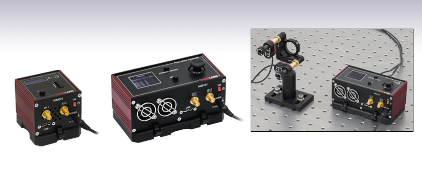
Four-Channel K-Cube Piezo Inertia Motor Controller
Application Idea
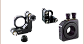
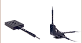
The KIM101 Controller features four channels, making it ideal for use with mirror mounts and beam steering applications.
KIM001
Single-Channel K-Cube Piezo Inertia Motor Controller


Please Wait
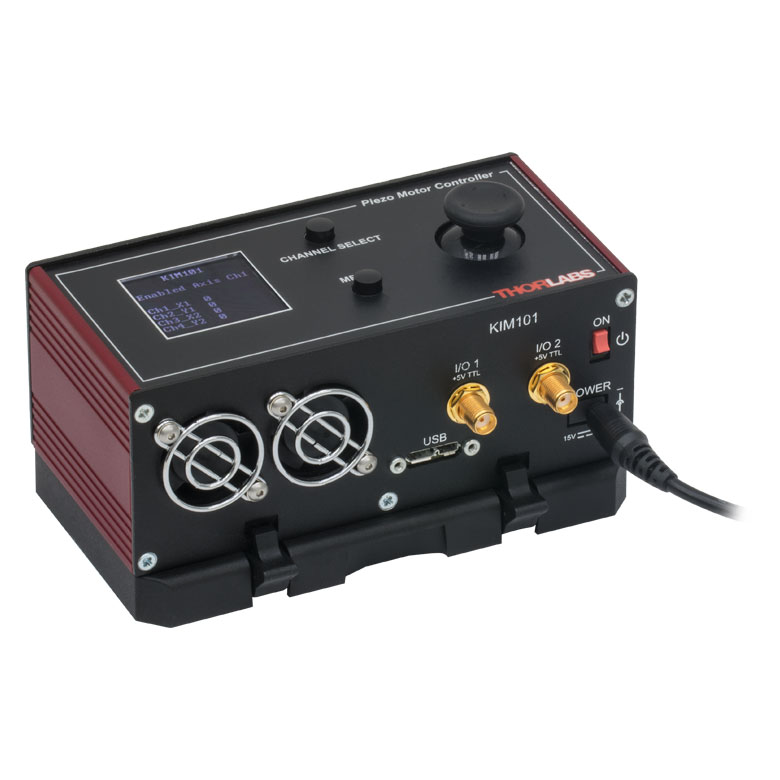
Click to Enlarge
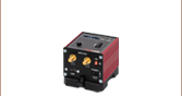
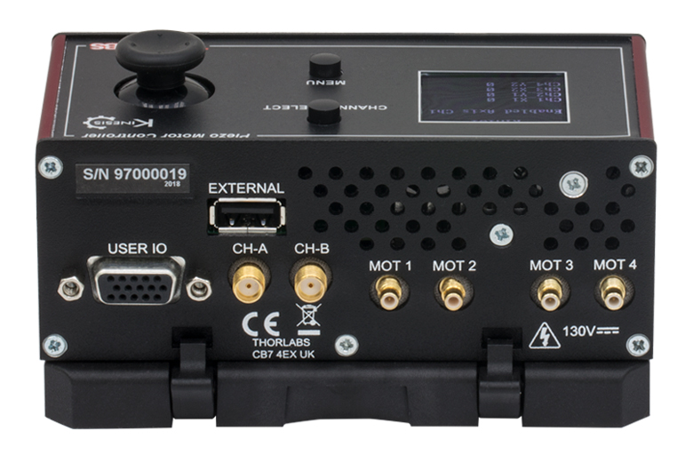
コントローラKIM101の背面(詳細は「ピン配列」タブをご覧ください)
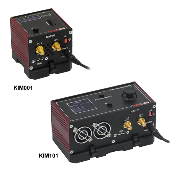
Click to Enlarge
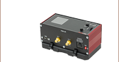
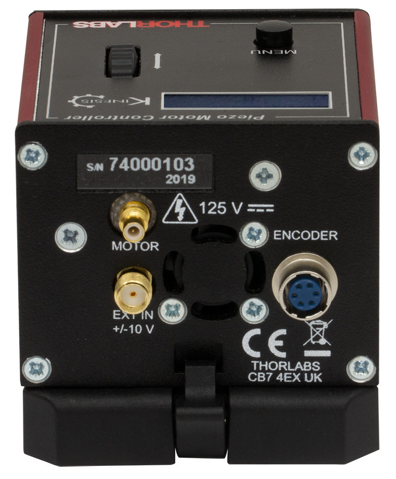
コントローラKIM001の背面(詳細は「ピン配列」タブをご覧ください)
| K-Cube™ Motion Control Modules |
|---|
| Brushed DC Servo Motor Controller |
| Brushless DC Servo Motor Controller |
| Fiber Alignment Controllers |
| Four-Channel Piezo Inertia Actuator Controller |
| PSD Auto Aligner |
| Single-Channel Piezo Controller |
| Single-Channel Combined Piezo Controller and Strain Gauge Reader |
| Solenoid Controller |
| Stepper Motor Controller |
特長
- コンパクトな設置サイズ
- 出力電圧の調整範囲:85 V~125 V
- 1チャンネルおよび4チャンネルのタイプをご用意
- ±10 Vのアナログ入力(SMAメス型、詳細は「ピン配列」タブをご覧ください)
- Kinesis®およびAPT™制御用ソフトウェア一式が付属
ピエゾ慣性モーターコントローラK-Cube™は、当社の制御用ソフトウェアKinesis®付きのコンパクトで高性能なモーションコントローラです。これらは当社の標準と真空対応のピエゾ慣性アクチュエータ、20 mm移動ステージPD1シリーズ、回転ステージPDR1/MおよびPIMシリーズのピエゾ慣性アジャスタ付き光学マウントを駆動するように設計されています。アダプターケーブルPD2ADを用いると、5 mm移動ステージ(PD2/M)および50 mm移動ステージ(PD3/M)にもご使用いただけます。シングルチャンネルコントローラKIM001は、1台のピエゾ慣性デバイスに対して電圧を供給します。4チャンネルコントローラKIM101には1チャンネルまたは2チャンネルで操作できる4つの出力端子があり、ビームステアリングや位置決めなどの用途に適しています。
ユニットの設置面積はコンパクトで、上面パネルの操作スイッチを使用してモータの位置を調整する際に、電動システムの近くに配置できるのも便利な点です。付属の取付けプレートの2つのM6ザグリ穴スロットを使用して、光学テーブルに直接取り付けることができます。また、この取付けプレートには磁石が2つ付いており、アセンブリを光学テーブルに置くだけで簡単に固定できます。
ユニット前面の電源スイッチでコントローラのON/OFFができます。上面パネルのディスプレイ画面を使用すれば、PCに接続しなくても、ユニットの電源をONにするだけですぐに操作を開始できます。スイッチをOFFにしても、すべてのユーザ設定は次回の起動時までK-Cube内に保存されています。なおユニットに電源を接続したり外したりするときは、電源スイッチは常にOFFの位置にしてください。
USB接続によるプラグアンドプレイで、Kinesisソフトウェアパッケージを使用したPCによる操作が簡単に行えます。Kinesisソフトウェアでは新しい.NETコントロールが使用できます。最新のC、C#、LabVIEW™、あるいはその他の.NETに対応する言語でカスタムプログラムを作成するサードパーティの開発者も、これを利用することができます。KIM101は、ActiveX®のプログラミング環境をベースとした従来のAPTソフトウェアを使用することもできます。KinesisおよびAPTソフトウェアパッケージはどちらも高度な動作制御を行えるため、複雑な動作シーケンスを素早く設定できます。 例えば、当社のピエゾ慣性デバイスの動作に関連するあらゆるパラメータはこのソフトウェアによって自動的に設定されます。2つのソフトウェアパッケージの詳細については、「モーションコントロールソフトウェア」、「Kinesisチュートリアル」および「APTチュートリアル」タブをご覧ください。
各K-Cubeには双方向のトリガーポートが2つあり、外部のロジック信号を読み取ったり、ロジック信号を出力して外部機器を制御したりすることができます。ポートを入力モードで使用する場合、ロジックレベルはTTLに対応しています。出力モードで使用する場合、ポートは5 Vのプッシュプル動作を行い、最大電流リミット値は約8 mAです。詳細はマニュアルをご覧ください。
注:このコントローラKIM101を直線移動ステージPD1/Mあるいは回転ステージPDR1/Mに使用するときは、コントローラのバージョンは2019年以降(S/Nラベルに記載)、ファームウェアはPD1/Mの場合010003以上(コントローラの電源ON時に表示)、PDR1/Mの場合は010004以上でなければなりません。それ以前のバージョンのコントローラKIM101や古いファームウェアを使用すると、PD1/MやPDR1/Mは適切に機能せず、またステージやコントローラの故障につながる場合があります。
電源
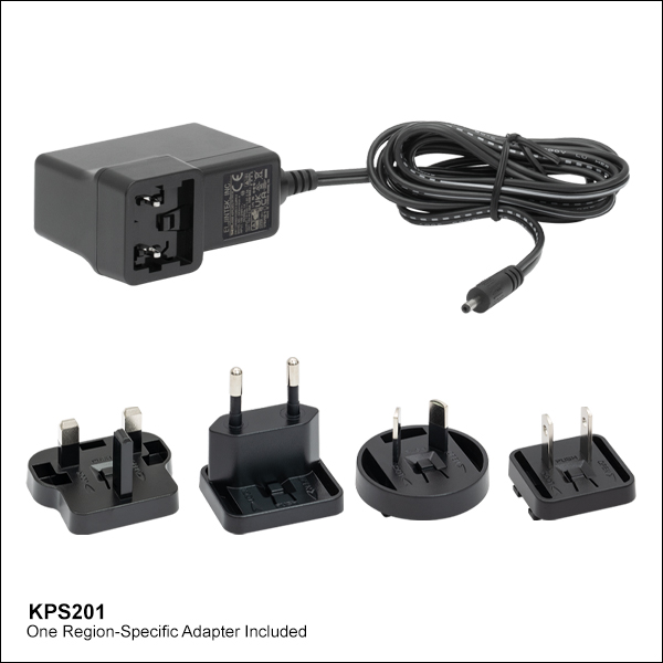
モーターコントローラKIM001およびKIM101には、電源は付属していません。対応する電源KPS201(下記参照)を別途ご提供しています。
注:設計上の特性、および非線形の高周波スイッチング技術を使用していることにより、KIM001およびKIM101はUSBコントローラハブ&電源KCH301およびKCH601には対応していません。ご使用いただける電源はKPS201のみです。
| Item # | KIM001 | KIM101 |
|---|---|---|
| Piezoelectric Outputs | One SMC Male | Four SMC Male |
| Voltage Output | 85 to 125 VDC | 85 to 125 VDC per Channel |
| External Input | SMA | SMA, CH-A, CH-B |
| Input Type | Single Ended, Analog | |
| Input Voltage | ±10 V ± 2%a | |
| Output Configuration | - | Individual Channels: Ch 1, Ch 2, Ch 3, Ch 4 Paired Channels: Ch 1 & 2; Ch 3 & 4 |
| Output Pulses | Frequency: 1 Hz to 2 kHz Voltage Peak Adjustable from 85 to 125 V | |
| Input Power Requirements | ||
| Voltage | 15 VDC | |
| Current | 1 A | 2 A |
| General | ||
| Operating Display | 128 x 32 LCD Mono | 128 x 128 TFT LCD Color |
| I/O 1 & I/O 2 Connectors | TTL Input, TTL Output, 5 V Level | |
| User I/O Connector | N/A | 15 Pin DIN 5 V @ 150 mA User Supply with 0 V Return Limit Switch Inputs (Qty. 8) - Multiplexed |
| Top Panel Controls | Spring-Loaded Scroll Wheel with Center Return: Velocity Control, Menu Control | Spring-Loaded 2-Axis Joystick with Center Return: Velocity Control of Selected Axis, Menu Control |
| USB Connector Type | USB 3.0 | |
| USB Connection Speed | USB 1.1 Full Speed (12 Mbps) | |
| Housing Dimensionsb (W x D x H) | 60.0 mm x 60.0 mm x 47.0 mm (2.36" x 2.36" x 1.85") | 121.0 mm x 60.0 mm x 47.0 mm (4.76 x 2.36" x 1.85") |
| Weight | 200 g | 390 g |
シングルチャンネル慣性モーターコントローラKIM001
モータ
SMCオス型

85~125 V。ピエゾアクチュエータに対する駆動信号を出力します。最大電圧は付属のKinesisソフトウェアで設定します。
PC接続
USB 3.0はUSB 1.1の通信速度をサポートします。USB2.0のMicro-Bタイプコネクタは、上図の網掛け部分に差し込むことで接続できます。KIM101にはAタイプ-Micro-BタイプのUSB 3.0ケーブルが1本付属します。
EXT IN
SMAメス型
入力:-10 V~10 V
アクチュエータの位置を制御するための外部アナログ信号源に接続するのに使用します。入力電圧範囲は-10 V~+10Vで、-10 Vで最大後退速度、+10 Vで最大前進速度が得られます。0 Vでは静止します。入力インピーダンスは100 kΩです。
I/O 1, I/O 2
SMAメス型
+5 V TTL
これらのコネクタでは5 Vロジックレベルの入出力を行いますが、外部機器と適切にトリガ信号の入出力ができるように構成することができます。ロジックレベルの調整やトリガの入力/出力の設定は、それぞれのポートごとに独立して行うことができます。
4チャンネル慣性モーターコントローラKIM101
MOT 1、 MOT 2、MOT 3、MOT 4
SMCオス型
85~125 Vピエゾアクチュエータに対する駆動信号を出力します。最大電圧は付属のKinesisソフトウェアで設定します。
PC接続
USB 3.0はUSB 1.1の通信速度をサポートします。USB2.0のMicro-Bタイプコネクタは、上図の網掛け部分に差し込むことで接続できます。KIM101にはAタイプ-Micro-BタイプのUSB 3.0ケーブルが1本付属します。
ユーザIO
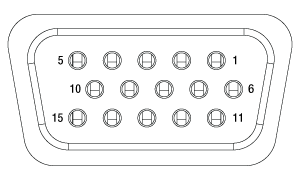
| Pin | Description | Pin | Description |
|---|---|---|---|
| 1 | 0 V | 9 | 0 V |
| 2 | OW-Aa | 10 | +5 V |
| 3 | OW-Ba | 11 | Limit Switch 3A/Encoder 3Ab |
| 4 | Limit Switch 1A/Encoder 1Ab | 12 | Limit Switch 3B/Encoder 3Bb |
| 5 | Limit Switch 1B/Encoder 1Bb | 13 | Limit Switch 4A/Encoder 4Ab |
| 6 | Limit Switch 2A/Encoder 2Ab | 14 | Limit Switch 4B/Encoder 4Bb |
| 7 | Limit Switch 2B/Encoder 2Bb | 15 | OW-Da |
| 8 | OW-Ca | - | - |
CH-A、CH-B
SMAメス型
入力:-10 V~10 V
アクチュエータの位置を制御するための外部アナログ信号源に接続するのに使用します。入力電圧範囲は-10 V~+10 Vで、-10 Vで最大後退速度、+10 Vで最大前進速度が得られます。0 Vでは静止します。入力インピーダンスは100 kΩです。
I/O 1, I/O 2
SMAメス型
+5 V TTL
これらのコネクタでは5 Vロジックレベルの入出力を行いますが、外部機器と適切にトリガ信号の入出力ができるように構成することができます。ロジックレベルの調整やトリガの入力/出力の設定は、それぞれのポートごとに独立して行うことができます。
K-Cube取付け
各K-Cubeユニットには、コントローラのベース部分をクリップで固定できる取付けプレートが付属します(下の動画参照)。プレートには2つの磁石が付いており、光学テーブルに一時的に設置する際にご使用いただけます。また、2つのM6キャップスクリュ用ザグリ穴は、恒久的に取り付ける際にご使用ください。光学テーブル取付けプレートの図面は「仕様」タブでご覧いただけます。
K-Cube用光学テーブル取付けプレート
T-Cubeとは異なり、すべてのK-Cubeにはコントローラをベースに固定するための取付けプレートが付属します。プレートには2つの磁石が付いており、光学テーブルに一時的に設置する際にご使用いただけます。また、恒久的な取り付けに使用できるM6キャップスクリュ用ザグリ穴も2つ付いています。
Kinesis®モーションコントローラのご紹介
| K-Cube™ vs. T-Cube™ Feature Comparison | |||
|---|---|---|---|
| Feature | KIM001 K-Cube | KIM101 K-Cube | TIM101 T-Cube |
| Kinesis Software Compatibility | |||
| APT Software Compatibility | N/A | ||
| Top Panel LCD Display | N/A | ||
| Power Switch | N/A | ||
| Piezoelectric Outputs (SMC Male) | One | Four | Four |
| Dual-Channel Operation | N/A | N/A | |
| Bidirectional SMA Trigger Portsa | Two | Two | N/A |
| SMA External Analog Inputa | |||
| Computer Connectiona | USB 3.0 Micro B (USB 2.0 Compliant) | USB 3.0 Micro B (USB 2.0 Compliant) | USB 2.0 Micro B (USB 2.0 Compliant) |
| Included Mounting Plate | |||
| Size (W x D x H) | (2.36" x 2.36" x 1.85") | ||
旧世代のT-Cubes™製品から大幅に改良されたK-Cube™のラインナップでは、新しいKinesisソフトウェアの導入だけでなく、物理的設計やファームウェアの全面的な見直しも行い、汎用性を高めています。なお、K-Cubeコントローラは当社の旧世代のAPTソフトウェアを用いても制御可能です。
すべてのK-Cubeコントローラにはデジタルディスプレイが付いています。基本的な入出力の読み取りのほか、シングルチャンネルコントローラKIM001にはスクロールホイールが付いており、それで1軸のピエゾ慣性アクチュエータまたはピエゾ慣性ステージを駆動できます。一方、4チャンネルコントローラKIM101にはジョイスティックが付いており、それを用いて2つの出力チャンネルを同時に制御できます。 どちらのユニットの前面にも電源スイッチが付いており、それをオフにするとユーザがセットした設定値はすべて保存されます。また、2つのSMAトリガーポートは双方向になっており、5 V TTLロジック信号の入力も出力も可能です。
右の表では、K-Cubeと旧世代のT-Cubeの2種類の慣性モーターコントローラの機能を比較しています。
Click to Enlarge
K-Cubeピエゾ慣性アクチュエーターコントローラKIM101
K-Cube用光学テーブル取付けプレート
T-Cubeとは異なり、すべてのK-Cubeにはコントローラをベースに固定するための取付けプレートが付属します。プレートには2つの磁石が付いており、光学テーブルに一時的に設置する際にご使用いただけます。また、2つのM6キャップスクリュ用ザグリ穴は、恒久的に取り付ける際にご使用ください。
注:KIM001にはKinesisソフトウェアを使用します。KIM101には、Kinesisソフトウェア、従来のAPTソフトウェアのどちらもご使用いただけます。
当社では幅広い種類のモーションコントローラを駆動できるよう、Kinesis® ソフトウェアパッケージと従来のAPT™(Advanced Positioning Technology)ソフトウェアパッケージの2種類のプラットフォームをご用意しております。どちらのパッケージも小型で低出力のシングルチャンネルドライバ(K-Cube™やT-Cube™など)から高出力でマルチチャンネルのモジュール式19インチラックナノポジショニングシステム(APTラックシステム)まで幅広い種類のモーションコントローラをカバーするKinesisシリーズのデバイスを制御できます。
Kinesisソフトウェアには、最新のC#、Visual Basic、LabVIEW™またはその他の.NETに対応する言語を使用してカスタムプログラムを作成するサードパーティの開発者向けに、.NETコントロールが付属しています。また、.NETフレームワークを使用しない用途向けに低級言語用のDLLライブラリも付いています。センターシーケンスマネージャが、当社の全てのモーションコントロールハードウェアの統合と同期をサポートします。

KinesisのGUIスクリーン
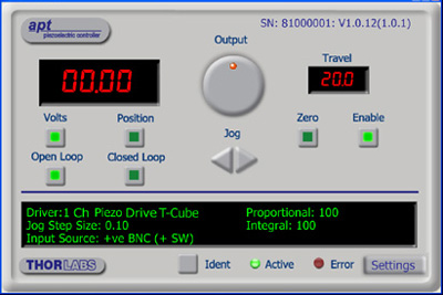
APTのGUIスクリーン
当社従来のAPTシステムソフトウェアプラットフォームは、C#、Visual Basic、LabVIEWまたはその他のActive-Xに対応する言語を使用してカスタムプログラムを作成するサードパーティの開発者向けに、ActiveXをベースとしたコントロールが付属しています。また、ハードウェア無しでカスタムプログラムの開発を行うためのシミュレーターモードも付いています。
これらの共通のソフトウェアプラットフォームにより、あらゆるKinesisとAPTコントローラをシングルアプリケーションに簡単に組み込むことができます。ソフトウェアツールは1セット習得するだけで共通した操作が可能です。シングルチャンネルシステムからマルチチャンネルシステムまで、あらゆるコントローラを組み合わせ、全てを1台のPCのソフトウェアインターフェイスから制御することが実現可能です。
このソフトウェアパッケージを使用するには2つの手段があります。GUI(グラフィカルユーザーインターフェイス)ユーティリティを使用したコントローラとの直接対話ならびに「out of the box」コントロール、またはご選択の開発言語でカスタム統合の位置決めやアライメントソリューションを簡単にプログラムできる一連のプログラミングインターフェイスです。
APTシステムソフトウェアをよりご理解いただけるために様々なチュートリアルビデオもご用意しております。ビデオではソフトウェアの概要とAPT Configユーティリティをご説明しています。また、ソフトウェアのシミュレーターモードを利用すると、コントローラを接続しないでソフトウェアを試すことができます。その方法を説明したビデオもあります。これらのビデオは「APTチュートリアル」タブ内のリンクからご覧いただけます。
ソフトウェア
Kinesis バージョン 1.14.47
このKinesisソフトウェアパッケージには、当社のKinesisならびにAPT™システムコントローラを制御するためのGUIが含まれています。
下記もご用意しております:
- 通信プロトコル
ソフトウェア
APT バージョン 3.21.6
このAPTソフトウェアパッケージには、当社のAPT™およびKinesisシステムコントローラを制御するためのGUIが含まれています。
下記もご用意しております:
- 通信プロトコル
Kinesis®ソフトウェアでは新しい.NETコントロールが使用でき、最新の最新のC#, Visual Basic, LabVIEW™、ほかの.NET対応言語を使用する開発者がカスタムにプログラムを作成することもできます。
C#
このプログラミング言語はマルチプログラミングパラダイムやマルチプログラミング言語が使用可能となるよう設計されているため、複雑な問題が簡単かつ効率的に解決できます。型付け、命令型、宣言型、関数型、ジェネリック、オブジェクト指向、そしてコンポーネント指向が含まれます。 この共通のソフトウェアプラットフォームにより、1セットのソフトウェアツールを習得するだけで、あらゆるKinesisコントローラを簡単に組み合わせることができます。このようにして1軸システムのコントローラから多軸システムのコントローラまで、様々なコントローラを組み合わせ、全てを1台のPCのソフトウェアインターフェイスから制御することが可能となりました。
Kinesisシステムソフトウェアを使用するには2つの手段があります。コントローラを直接つないで制御を行なう付属のGUI(グラフィカルユーザーインターフェイス)ユーティリティ、またはご希望の開発言語でカスタム仕様の位置決めやアライメントを簡単にプログラムできる一連のプログラミングインターフェイスです。
Kinesisモーションコントロールライブラリの構築の参考となる実行可能なプロジェクト機能拡張例については下のリンクをクリックしてください。なお、Quick Startのプロジェクト例の実行には別の統合開発環境(IDE)(Microsoft Visual Studioなど)が必要です。C#のプロジェクト例はKinesisソフトウェアパッケージに付属する.NETコントロールで実行可能です(詳細は「Kinesisソフトウェア」タブをご覧ください)。
 | Click Here for the Kinesis with C# Quick Start Guide Click Here for C# Example Projects Click Here for Quick Start Device Control Examples | |
LabVIEW
LabVIEWは、.Netコントロールを介してKinesisまたはAPTベースのコントローラとの通信に使用できます。LabVIEWでは、ツールとオブジェクトでフロントパネルとして知られるユーザーインターフェイスを構築した後、グラフィカル表記の関数を使ってコードを追加し、フロントパネルのオブジェクトを制御します。下記のLabVIEWチュートリアルでは.Netコントロールを使用してLabVIEW内KinesisまたはAPT駆動デバイス用の制御GUIを作成するための情報をご提供しています。 LabVIEWでコントローラを制御する基本的な方法や、LabVIEW GUIを用いてデバイスを操作する前に行うべき設定の手順についても解説しています。
 | Click Here to View the LabVIEW Guide Click Here to View the Kinesis with LabVIEW Overview Page | |
こちらのページでご覧いただくAPTビデオチュートリアルは、付属のATPユーティリティに関する説明と、いくつかのプログラミング環境におけるAPTシステムのプログラミングに関する説明の2つの部分から構成されています。
免責事項:これらの動画は、当初はAdobe Flashによって作成されました。2020年のAdobe Flashのサポート終了後、これらのチュートリアルは再録画されています。各動画の下にはFlash Playerの操作ボタンが見えますが、機能はしません。
APTコントローラには、APTUserユーティリティとAPTConfigユーティリティが付いています。APTUserを用いると、直感的操作が可能なグラフィック制御パネルを介して、APTで制御するハードウェアに素早く簡単に接続することができます。APTConfigは「オフライン」ユーティリティで、メカニカルステージのタイプを事前に選択し、それらを特定のモーションコントローラに対応付けるなど、システム全体のさまざまな設定を行うことができます。
APT Userユーティリティ
下の左側の動画では、APTUserユーティリティの操作概要について説明しています。シングルチャンネルコントローラのOptoDriverは、制御用のPCが無くても前面パネルのコントローラを介して操作できます。前面パネルのコントローラに保存されている操作に関する設定は、APTUserユーティリティを使用して変更することができます。そのプロセスは下の右側の動画でご覧いただけます。
APT Configユーティリティ
シミュレートされたハードウェア構成のセットアップや、メカニカルステージの特定のモータードライブチャンネルへの対応付けなど、APT Configユーティリティを使用してAPTシステム全体の様々な設定ができます。下の最初の動画ではAPT Configの概要をご覧いただけます。シミュレートされたハードウェア構成の作成方法やステージと対応付ける方法についての詳細は、その右側の2つの動画でご覧いただけます。
APTのプログラミング
APTソフトウェアシステムは、ActiveXコントロールのコレクションとして実装されています。ActiveXコントロールは言語に依存しないソフトウェアモジュールで、グラフィカルユーザーインターフェイスとプログラミングインターフェイスの両方を提供します。ハードウェアユニットのタイプごとにActiveXコントロールのタイプがあります。例えば、Motor ActiveXコントロールはすべてのタイプのAPTモーターコントローラ(DCまたはステッパ)の操作に対応します。ActiveXコントロールは多くのWindowsソフトウェア開発環境やソフトウェア言語で直接サポートされており、そのようなコントロールがカスタムアプリケーションに組み込まれると、そこに含まれるすべての機能が即座にアプリケーションで利用できるようになります。下の動画では、LabVIEW、Visual Basic、Visual C++によるAPT ActiveXコントロールの基本的な使用方法について説明しています。これ以外に、LabWindows CVI、C++ Builder、VB.NET、C#.NET、Office VBA、Matlab、HPVEEなどの多数の言語でもActiveXはサポートされています。これらの言語環境についてはチュートリアルのビデオでは特に取り上げていませんが、動画内の考え方の多くは他の言語環境でも適切に使用できます。
Visual Basic
Part 1ではVisual Basicで動作するAPT ActiveXコントロールを設定する方法について説明しており、Part 2では独自の位置決めシーケンスをプログラミングする方法について説明しています。
LabVIEW
LabVIEWはActiveXをフルサポートしています。下の一連のチュートリアルビデオでは、APTによる独自のモーションコントロールシーケンスを作製する際の基本的な構成要素を示しています。まずソフトウェア開発中にオンラインヘルプを呼び出す方法をご紹介します。Part 2ではAPT ActiveXコントロールの作成方法をご紹介します。ActiveXコントロールではメソッド(機能)とプロパティ(数値設定)の両方を設定できます。Part 3と4では、ActiveXコントロールで示されたメソッドとプロパティを作成してワイヤで接続する方法をご紹介します。最後に、Part 5では全体をまとめて、独自の移動シーケンスを実行するLabVIEWのプログラム例をご紹介します。
Part 1:オンラインヘルプへのアクセス方法
Part 2:ActiveXコントロールの作成方法
Part 3:ActiveXのメソッドの作成方法
Part 4:ActiveXのプロパティの作成方法
Part 5:ActiveXコントロールの開始方法
下のチュートリアルビデオでは、メソッドおよびプロパティのノードを作成する別の方法について説明しています。
ActiveXメソッドの作成方法(別の方法)
ActiveXプロパティの作成方法(別の方法)
Visual C++
Part 1ではVisualC++で動作するAPT ActiveXコントロールを設定する方法について説明しており、Part 2では独自の位置決めシーケンスをプログラミングする方法について説明しています。
MATLAB
当社のAPTポジショナにMATLABおよびActiveXコントロールを使用する場合は、こちらの資料をご覧ください。
プログラマー向けとして、LabVIEWでAPTソフトウェアをプログラミングする方法もこちらからご覧いただけます。
| Posted Comments: | |
Nate Kimmitt
(posted 2023-11-10 10:20:47.223) Hi,
I'm trying to control the KIM101 in Matlab. Is there an example you could provide for me?
Thanks,
Nate do'neill
(posted 2023-11-13 07:29:43.0) Feedback from Daniel at Thorlabs. I will reach out to you directly to provide this example. Jim Cordova
(posted 2023-11-01 15:22:45.07) Does the KIM101 have built-in protection to protect the piezo motor on an active stage if it runs into a mechanical hard stop?
Or, is the piezo motor immune to such damage?
Thanks,
Jim do'neill
(posted 2023-11-13 06:26:24.0) Response from Daniel at Thorlabs. Our piezo inertia actuators do not have feedback to allow for our KIM101 to tell it has reached the limit. It would be possible for the user, using a 3rd partly software/language, to create a software form of a limit switch if something is added to the application to provide this feedback.
Also, the PIAs, due to the slip stick design, do not have an issue being over driven as the leadscrew will just not move. This is not an issue as long as this is only for a short period. Continuous overdriving past the limit for prolonged periods will cause wear and damage to the mechanism. Da Lieshout
(posted 2023-10-05 07:12:40.663) Ah, for the COM-port had to right click on the ATP USB, Advanced and check the box of "Load VCP" (that is Virtual Com Port). Case closed. do'neill
(posted 2023-10-10 10:30:44.0) Response from Daniel at Thorlabs. Glad to hear this is resolved, don't hesitate to reach out if you have further issues. Da Li
(posted 2023-10-04 12:31:48.323) Have a KIM101 working on older laptop.
Have to install on a new laptop. Old an new has installed the x64 software.
After install ATP and Kinesis we do not see a COM-port in the Windows Device Manager. What could be wrong. Is there another driver available? user
(posted 2023-09-25 14:14:19.177) Hi, could you please help me? I am continuously obtaining this error message in LabView:
Expected Assembly "Thorlabs.MotionControl.Controls, Version=1.14.12.0, Culture=neutral, PublicKeyToken=c7ec6d6d6e2435e7", but found "Thorlabs.MotionControl.Controls, Version=1.14.37.21486, Culture=neutral, PublicKeyToken=c7ec6d6d6e2435e7."
I used to work with different types of KCube motors and everything works well. However, I am unable to control the Piezo Motor Controller in LabView. do'neill
(posted 2023-09-27 10:25:39.0) Response from Daniel at Thorlabs. I will reach out to you directly to help troubleshoot this to find where the error might be coming from and help you with fixing it. junyeop kim
(posted 2023-08-09 14:23:31.92) I'm trying to connect with KIM101 using MATLAB.
I succeeded in conncet to KIM101. But it failed to find channel1 via InertialMotorStatus. (I approached it the same way as the python example you provided.)
Looking at the previous comments, it seems that there is already an example provided.
If possible, can I get a MATLAB example for KIM101? do'neill
(posted 2023-08-09 10:46:12.0) Response from Daniel at Thorlabs. I will reach out to directly with an example for this. TaiBei Liu
(posted 2023-07-04 20:01:52.697) Can you provide me with a document about my own programming operations?C# or labelview or c++ or matlab... fguzman
(posted 2023-07-06 10:52:26.0) Thanks for your enquiry. For this item we have some guidelines in our website https://www.thorlabs.de/newgrouppage9.cfm?objectgroup_id=9790&pn=KIM001&tabname=Kinesis%20Tutorials
Also, our Kinesis software features .NET controls which can be used by 3rd party developers working in C#, LabVIEW etc. There is also low-level DLL libraries included for applications not expected to use the .NET framework. We have several examples in our GitHub page: https://github.com/thorlabs Nadav Frenkel
(posted 2023-05-18 23:21:37.087) Im trying to establish a connection with KIM101 using MATLAB.
I'm using a code (attached below) provided by Thorlabs that uses the DLLs found in the Kinesis folder and I'm using DotNet_API to alter the command to be correct specifically to KIM101.
However, I'm having a hard time connecting to the device and understanding what are basic commands needed to establish the connection.
Moreover, if the connection for some reason fails, I am no longer able to connect to the device (meaning, passing the "connect" line successfully) without turning it OFF and ON back.
Are you aware of such problems? do you have any suggestions on what can I do differently?
Code:
%You can use the Kinesis .NET dll library in Matlab to control the stages.
% After download and install of Kinesis Thorlabs - Your Source for Fiber Optics, Laser Diodes, Optical Instrumentation and Polarization Measurement & Control.
% you can find the dll files in the folder C:\Program Files\Thorlabs\Kinesis
% The DotNet_API help file is also in this folder.
% I send you a Matlab code example for the KDC101 controller in the attachment.
%Example for programming the Thorlabs KDC101 with Kinesis in MATLAB, with PRM1-Z8 stage.
clear all
%Load assemblies
NET.addAssembly('C:\Program Files\Thorlabs\Kinesis\Thorlabs.MotionControl.DeviceManagerCLI.dll');
% NET.addAssembly('C:\Program Files\Thorlabs\Kinesis\Thorlabs.MotionControl.GenericMotorCLI.dll');
% NET.addAssembly('C:\Program Files\Thorlabs\Kinesis\Thorlabs.MotionControl.KCube.DCServoCLI.dll');
NET.addAssembly('C:\Program Files\Thorlabs\Kinesis\Thorlabs.MotionControl.KCube.InertialMotorCLI.dll');
% NET.addAssembly('C:\Program Files\Thorlabs\Kinesis\Thorlabs.MotionControl.KCube.InertialMotor.dll');
% NET.addAssembly('C:\Program Files\Thorlabs\Kinesis\Thorlabs.MotionControl.DeviceManager.dll');
%Initialize Device List
import Thorlabs.MotionControl.DeviceManagerCLI.*
% import Thorlabs.MotionControl.GenericMotorCLI.*
% import Thorlabs.MotionControl.KCube.DCServoCLI.*
import Thorlabs.MotionControl.KCube.InertialMotorCLI.*
%% Create Simulation
% SimulationManager.Instance.InitializeSimulations();
%Initialize Device List
try
DeviceManagerCLI.BuildDeviceList();
DeviceManagerCLI.GetDeviceListSize();
%Should change the serial number below to the one being used.
serial_num='97102270';
timeout_val=60000;
%Set up device and configuration
device = KCubeInertialMotor.CreateKCubeInertialMotor(serial_num);
device.Connect(serial_num);
device.WaitForSettingsInitialized(5000);
deviceInfo = device.GetDeviceInfo();
% configure the stage
motorSettings = device.GetInertialMotorConfiguration(serial_num);
motorSettings.DeviceSettingsName = 'KIM101';
% update the RealToDeviceUnit converter
motorSettings.UpdateCurrentConfiguration();
% push the settings down to the device
MotorDeviceSettings = device.MotorDeviceSettings;
device.SetSettings(MotorDeviceSettings, true, false);
device.StartPolling(250);
pause(1); %wait to make sure device is enabled
%Home
device.Home(timeout_val);
fprintf('Motor homed.\n');
%Move to unit 100
device.MoveTo(100, timeout_val);
%Check Position
pos = System.Decimal.ToDouble(device.Position);
fprintf('The motor position is %d.\n',pos);
device.StopPolling()
device.Disconnect()
catch
disp('error')
device.Disconnect()
end do'neill
(posted 2023-05-19 07:01:59.0) Response from Daniel at Thorlabs. I will reach out to you directly to discuss this with you and help you with your application and provide you an example for controlling the KIM101 in MATLAB. Adam Smith
(posted 2023-01-20 17:17:39.017) Hi, Is it possible to control the KIM101 using a separate ic or arduino or any other way not through the software. To clarify, can i just drive the control signals myself or does it have to be through the software.
Thanks JReeder
(posted 2023-01-24 04:41:41.0) Thanks for your enquiry. Our Kinesis software features .NET controls which can be used by 3rd party developers working in C#, LabVIEW etc. There is also low-level DLL libraries included for applications not expected to use the .NET framework. We have several examples in our GitHub page: https://github.com/thorlabs. There is also the option to use serial commands with theses devices, the communications protocol can be found here: https://www.thorlabs.com/software_pages/ViewSoftwarePage.cfm?Code=Motion_Control&viewtab=2. If you are looking to only drive this using an external voltage source there is an External input SMA which accepts -10 V to +10 V. I have reached out to you to discuss your application further. user
(posted 2022-08-24 12:05:58.607) Hi,
When I looked through the details about the KIM101, I couldn't find out the specification of output current from each channel.
Can you let me know any information about that (Ex: The maximum output current from each channel, or the range of the output current )?
Thanks a lot. DJayasuriya
(posted 2022-08-24 07:01:02.0) Thank you for your inquiry. This would have couple of things to consider; the output driver is designed specifically for our PIAs within a certain range of capacitance and output driver is totally non-linear and is made up of two separate parts. We have got in touch with more details. Théo Geral
(posted 2022-04-19 13:10:26.227) Hello,
I'm looking for python help controlling the KIM101. I saw that you already send some exemples to other users. Could you send them to me please ? Thank you. cwright
(posted 2022-04-21 08:38:26.0) Response from Charles at Thorlabs: Thank you for your query. Python is not a language which we can officially support but we do have a couple of examples. I will reach out to you with one for the KIM101. Juan sebastian Leon. Rodriguez
(posted 2022-02-23 20:57:35.0) What kind of license do you use for the API provided by you, both in C++ and C# for the use and creation of programs that control the KIM101 device created by you, are the dll's open source or is it under some kind of paid licensing for its use? DJayasuriya
(posted 2022-02-24 10:58:05.0) Thank you for your inquiry, The dll's can be found when you download our software, it is not under any paid licensing. Similarly communications protocol can be found on our website : https://www.thorlabs.com/Software/Motion%20Control/APT_Communications_Protocol.pdf user
(posted 2021-11-10 00:51:52.6) Hi, I am trying to control KIM101 using C# example "KPZ_KCubePiezoController " under "Quick Start Device Control Examples" but I always connect failed.I get error message below:
"Unable to connect to device
Thorlabs.MotionControl.DeviceManagerCLI.DeviceNotReadyException: Device is not connected"
Could you send me some examples of KIM101. Thank you. cwright
(posted 2021-11-10 05:21:00.0) Response from Charles at THorlabs: Thank you for your query. The example you refer to is for simple piezo controllers. The KIM controlls what we term "Piezo Motors" as they operate very differently than a typical piezo. I will reach out to you with an example. user
(posted 2021-08-10 10:36:18.267) I am looking to set up a closed loop system with the KIM101 and was looking to receive some guidance as I cannot figure out if the KIM101 supports a closed loop system. cwright
(posted 2021-08-18 04:39:01.0) Response from Charles at Thorlabs: Thank you for your query. Feedback from the KPA101 can be used in conjunction with the KIM101 CH-A, CH-B inputs for a closed loop system which maintains the system on a point. The limit/encoder pins are for future use as we develop PIA’s with feedback, though they can be used as limit switches. I will reach out to you to discuss your application. Michael Pfeiffer-Härtl
(posted 2021-01-26 01:24:27.887) Hello,
is there a specification available which describes the programming interface/control commands of these controllers? The idea is to use the out of an own application but not with the software you recommend. DJayasuriya
(posted 2021-01-27 03:43:35.0) Thank you for your inquiry. Yes, we do provide the.dll files(some assemblies are .NET dlls and some are Native C dlls) with the software download. You will also have access to the .NET API Help document (file path C:\Program
Files\Thorlabs\Kinesis\Thorlabs.MotionControl.DotNet_API).
Please have a look at the our communication protocol for low level communication protocol: https://www.thorlabs.de/Software/Motion%20Control/APT_Communications_Protocol.pdf
Hope this helps. If you have any questions, do not hesitate to get in touch with your local tech support team, who would be happy to help. Peter Coffell
(posted 2020-11-14 16:46:47.63) Hello,
I was wondering if he KIN 101 can control brushed motors also? cwright
(posted 2020-11-17 05:37:35.0) Response from Charles at Thorlabs: Hello and thank you for your query. This controller is not intended to be used to control DC motors and has no settings to facilitate this. Further, the voltage it outputs is a sawtooth waveform which can only be adjusted from 85 - 125V. The motor would see an averaged but high voltage which would damage the motor. We recommend the KDC101 to control brushed dc motors. D W
(posted 2020-11-05 04:52:16.697) Is there any way to determine when the KIM device has finished moving using the C API?
The documentation hints that this might be possible using KIM_WaitForMessage (at least for different types of motors), however it doesn't seem to emit anything when it's finished moving. The messages it occassionally emits while moving (messageType==12, messageID==0) are completely undocumented.
The "status bits" (e.g. KIM_GetStatusBits()) look like they might also be relevant, but the output is also undocumented. cwright
(posted 2020-11-06 09:07:44.0) Response from Charles at Thorlabs: thank you for your query. It appears that our documentation may be lacking some updates relevant to the KIM. We will look into this and contact you directly to follow up. Ari Feldman
(posted 2020-09-28 18:30:01.243) Looking for python help controlling the KIM101. Others have received examples on how to interface the dll with ctypes. Could you also share with me? DJayasuriya
(posted 2020-10-06 03:42:21.0) Thank you for your inquiry. Yes of course, we will get in touch with you directly with an example python code and to discus your application. user
(posted 2020-04-27 03:04:54.54) Hello, is it possible to control KIM001 with Matlab appdesigner? DJayasuriya
(posted 2020-04-27 10:55:27.0) Response from Dinuka at Thorlabs: Thank you for your inquiry at the moment we would not be able to directly support MATLAB app designer, but I will get in touch with you directly to see if we can help with your application. Joseph Natal
(posted 2020-02-17 00:05:04.76) Hi. I'm wondering if these K-Cube or T-cube controllers could be useful for vibration damping applications. I'm thinking I may purchase the high voltage piezo amplifier to use with a controller I make myself, incorporating a third party position sensing device for active feedback. The project is to create my own controller, so I figure I should just purchase the amplifier. This would be for a UC Berkeley course with possible application Lawrence Berkeley National Lab, where I work at the BELLA center.
Thanks,
Joe DJayasuriya
(posted 2020-02-19 04:09:02.0) Response from Dinuka at Thorlabs: Hello Joe, Thank you for contacting us. It seems like you are trying to use the cube for active vibrational damping. The K cube or T cube controllers would not be able to achieve what you are looking for. However I will get in touch with you directly to discuss your application. user
(posted 2020-01-10 07:55:11.823) Just to explain a bit further about the symptom of the problem with KIM101 after the firmware update.. After the firmware update, I can see the USB Device Node on the FirmwareUpdateUtility, but it does not show any controller that can/cannot be reprogrammed. So I cannot Flash Firmware again nor control the piezo inertia stage (PD1) How can I solve this problem? cwright
(posted 2020-01-22 04:24:54.0) Response from Charles at Thorlabs: thank you for contacting us about this. It appears that your firmware has been corrupted. This is most likely caused by a loss of power to the device during reprogramming. This may be something which can be quickly fixed at the users end or it may be necessary for us to reprogram it at one of our offices. I will reach out to you directly to troubleshoot this. user
(posted 2020-01-10 05:42:42.8) We have recently purchased KIM101 (to control PD1 stages). Initially it was possible to control it with the APTUser software on a computer. But after I accidentally updated the firmware using the Thorlabs FirmwareUpdateUtility, the device (KIM101) is not even recognized by the computer. Could you please help me regarding this? Alan Blair
(posted 2019-05-22 12:19:27.563) We would like to embed this in a device which will be remotely controlled. Can you tell me how the power switch is connected so we can make a remote circuit to emulate it? Alternatively, there is a connector on the bottom of the KIM101. Can this be used to control the on/off functionality? AManickavasagam
(posted 2019-05-28 05:11:29.0) Response from Arunthathi at Thorlabs: Thanks for your query. I have contacted you directly with the details of the power switch connection and feasibility of controlling the KIM101 remotely along with the circuit diagram for your reference. e.lopez
(posted 2018-11-23 08:22:36.45) Can this controller be controlled by Matlab?
Thank you,
Eneko rmiron
(posted 2018-11-23 04:00:04.0) Response from Radu at Thorlabs: There are multiple paths for controlling KIM101 from MATLAB. One would be to use the ActiveX controls that come with APT, our legacy software. We have a short guide on how to get started. You can download it via this link: https://www.thorlabs.com/tutorials/Thorlabs_APT_MATLAB.docx
A second option would be to bypass our software and send serial commands directly from MATLAB to the device. You can find the documentation for our serial communications protocol here: https://www.thorlabs.com/Software/Motion%20Control/APT_Communications_Protocol.pdf
Finally, our .NET API for Kinesis can be used from MATLAB, but we don't have any guides or examples that can help you get started. I should mention that the API is composed of .NET assemblies, as opposed to COM DLLs. michael.nickerson
(posted 2017-10-18 11:10:29.133) This TIM101 would be far more useful if it could be controlled by the KPA101 or other KCH-mountable controllers, instead of manual control only. AManickavasagam
(posted 2017-10-27 11:36:06.0) Response from Arunthathi at Thorlabs: Thank you for your query. Unfortunately, without external electronics there is no way to control TIM101 with KPA101 for beam stabilisation/tracking.
We will note this requirement and notify our engineers. user
(posted 2017-07-11 15:02:32.83) Can this controller be controlled by a Python script ? I've found some modules online (thorlabs_apt and PyAPT), but they don't seem to be working with TIM101. I'm trying to send it instructions depending on some data returned by a Python program, in order to calibrate the position of a laser beam with two piezo inertia actuators mounted on a mirror. bhallewell
(posted 2017-07-13 09:36:41.0) Response from Ben at Thorlabs: Unfortunately we do not support use of APT through Python. What we do have available is a number of videos & guides found in the following webpage for Visual Studio (Basic & C++) & LabVIEW.
We also hold examples for programming in our latest motion control software, Kinesis, through LabVIEW & Visual Studio (C# & C) environments.
https://www.thorlabs.com/navigation.cfm?guide_id=2251 peebles
(posted 2016-07-19 12:54:47.94) Does the controller allow you to set a specific distance of translation when coupled with a suitable piezo transducer and translation stage.
If so what would be the accuracy of the final distance moved e.g. If asked to move the translation stage 1 cm, how accurate would be the final movement?
Also is there any sort of readout of position ?
Thanks, Tony Peebles
Our application requires ~2cm movement of a plastic lens weighing about 2 pounds in both horizontal and vertical directions. bwood
(posted 2016-07-20 03:54:37.0) Response from Ben at Thorlabs: Thank you for your question. The TIM101 cannot provide the position of the actuator in meters, due to the varying step size it can only output the number of steps. Furthermore, the TIM101 cannot currently be coupled with an external feedback mechanism, to calculate the position within the controller and our motion control software hemselves. One potential solution would be to use an external feedback mechanism to measure the position, and to generate a control signal to the analogue input of the TIM101 to move the actuator to a given position. This would create a closed loop system, similar to a conventional closed loop piezo system. |

 ズーム
ズーム| Key Specificationsa | ||
|---|---|---|
| Item # | KIM001 | KIM101 |
| Piezoelectric Outputs (SMC Male) | One | Four |
| Piezo Output Voltage | 85 to 125 VDC | 85 to 125 VDC per Channel |
| Top Panel Controls | Scroll Wheel | Dual-Axis Joystick |
| External Input (SMA Female) | ±10 V ± 2% | |
| Input Power | +15 VDC @ 2 A | |
| Housing Dimensionsb | 60.0 mm x 60.0 mm x 47.0 mm (2.36" x 2.36" x 1.85") | 121.0 mm x 60.0 mm x 47.0 mm (4.76" x 2.36" x 1.85") |
| Compatible Software | Kinesis | Kinesis & Legacy APT |
- 詳細な仕様については下の赤いアイコン(
 )をクリックしてマニュアルをご覧ください。
 - 取付けプレートは含みません。
- 上面パネルの操作スイッチとディスプレイ画面により単体での操作が可能
- USB接続によるプラグアンドプレイでPC制御が可能
- 出力電圧の調整範囲:85 V~125 V
- 電源は付属しません(下記にて別売り)
こちらのコンパクトなK-Cubeコントローラを用いると、当社のピエゾ慣性ステージ、ピエゾ慣性アクチュエータ、ピエゾ慣性アジャスタ付き光学マウントなどに対して、簡単なマニュアルやPC制御が可能になります。出力電圧の調整範囲は85 V~125 Vです。上面パネルのディスプレイ画面を使用すれば、PCに接続しなくても、ユニットの電源をONにするだけですぐに操作を開始できます。また、どちらのコントローラもUSB接続によるプラグアンドプレイで、当社のKinesis®ソフトウェアパッケージ(付属します)を用いたPC制御が可能になります。コントローラKIM101は、当社の従来のAPT™ソフトウェアパッケージを使用して操作することもできます。
これらのコントローラには電源が付属しませんのでご注意ください。対応可能な電源は下記でご紹介しています。
シングルチャンネルコントローラKIM001
シングルチャンネルピエゾ慣性コントローラは、1台のピエゾ慣性ステージまたはピエゾ慣性アクチュエータに対して電圧を供給できます。上面パネルにはバネ付きのスクロールホイールがあり、これを用いてステージやアクチュエータを操作したりメニューを選択したりできます。
4チャンネルコントローラKIM101
4チャンネルコントローラには、ピエゾ慣性デバイスを駆動するためのSMC出力端子が4つ付いています。これらのチャンネルは、上面パネルの2軸ジョイスティックを使用してそれぞれ単独あるいはペアで操作できます。コントローラは、最大4台までのPDシリーズピエゾ慣性ステージまたは PIAシリーズピエゾ慣性アクチュエータ、あるいは2台までのPIMシリーズ ピエゾ慣性光学マウントを操作するように設定できます。1台のKIM101では、コントローラのメニュー選択において同じ「Select Stage」を選択するデバイス以外は、同時に駆動することはできません(詳細はマニュアルに記載されています)。

 ズーム
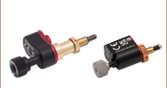
ズーム- モーターコントローラKIM001およびKIM101に対応
- 日本国内向けのアダプタープラグが付属
電源KPS201の出力電圧は+15 VDC、最大電流は2.66 Aで、3.5 mmジャックで1台のK-CubeまたはT-Cubeに電力を供給します。標準的な壁コンセントに接続して使用します。