 Products Home
PRO8半導体レーザーコントローラーモジュール
- Ultra-Stable Current Control
- Extensive Laser Diode Protection
- External Modulation of Laser Output
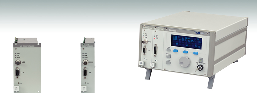
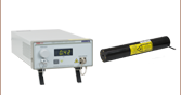
LDC8080
Module
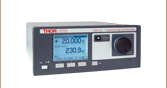
LDC8040
Module
LDC8040 & TED8040 Modules
Inside a PRO800 Chassis

Please Wait
| Key Specificationsa | ||
|---|---|---|
| Item # | Max Laser Diode Current | Module Width |
| LDC8001 | ±100 mA | 1 Slot |
| LDC8002 | ±200 mA | |
| LDC8005 | ±500 mA | |
| LDC8010 | ±1 A | |
| LDC8020 | ±2 A | |
| LDC8040 | ±4 A | |
| LDC8080 | ±8 A | 2 Slots |
| PRO8 Series Modulesa | |
|---|---|
| Laser Diode Current Controllers (Up to 8 A) | 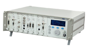 |
| TEC Temperature Controllers (Up to 64 W) | |
| Combination Laser Diode Current (Up to 1 A) & TEC Temperature Controllers (Up to 16 W) | |
| DWDM DFB Laser Modulesb | |
| Optical Switches | |
| Photocurrent Measurement Modules | |
特長
- 電流範囲: 0~±100 mA、±200 mA、±500 mA、 ±1 A、 ±2 A、±4 A、±8 A
- アノード接地(AG)およびカソード接地(CG) 極性をサポート
- 定電流(CC)および定光出力(CP)動作をサポート
- DCから200 kHzまでの3 dBアナログ変調帯域
- 16ビット設定の分解能
- レーザを保護
はじめに
PRO8プラットフォーム向けの当社の半導体レーザーコントローラーモジュールは、低電流ノイズと低ドリフトで、レーザの安定性に優れています。PRO8シリーズシャーシにこちらのモジュールを予め取り付けてご提供することも可能です。ご注文前に当社までご連絡ください。
7種類の電流範囲
最大出力電流が100 mA~8 Aの7種類の電流コントローラーモジュールからお選びいただけます。駆動電流は16ビットの分解能(1/65,000)で精密に設定できます。全てのLDC8000モジュールは、定電流(CC)または定格パワー(CP)モードのどちらかで動作可能です。
使い易い制御性
PRO8の表示メニューによって、シャーシ内のあらゆるモジュールを簡単に設定できます。簡略表示記号により、あらゆる操作パラメータへ簡単にアクセスできます。全ての設定はメモリに保存され、モジュールが違うスロットに移動しない限りメインフレームの電源を入れると自動的に再設定されます。
内蔵半導体レーザ保護機能
LDC8000シリーズの電流制御モジュールには、デリケートな半導体レーザを保護するためのレーザ保護機能が組み込まれています。 電流リミット、ソフトスタート、割り込み保護機能に加えて、高度な回路設計により、半導体レーザーはACパワーのインライン型トランジェントやパワー出力、RFピックアップによって影響を受けません。
それぞれの電流モジュールには、レーザを保護する3つの別々のリミットが設定されています。リミットの2つはプログラムが可能で、レーザ電流とレーザ出力がユーザ定義の最大値を超えるのを防ぎます。3番目のリミットはフロントパネルの凹型トリムポットを介して設定されます。トリムポットは「ハードウェア」電流リミットを定義してプログラミングのエラーやノブの誤調整を防ぎます。レーザ電流を外部で変調しても、ハードリミットやソフトリミットを越えることはできません。半導体レーザを始動すると、ソフトスタート機能により、レーザはオーバーシュートやスパイクを生じずにレーザ電流を滑らかに上昇させます。
AC電源が切断されても、レーザに過渡電流は流れません。AC ラインの電圧ピークは、電気フィルタ、変換器のシールド、モジュールやシャーシの接地により効率的に抑制されます。LDC8000シリーズは、レーザ保護に関する国際要求定義(例:CDRH US21 CFR 1040.10やIEC 60825-1)を満たしています。PRO8システムにはキー操作パワースイッチとインターロックが含まれています。
当社ではこれらのモジュールを24か月ごとに校正することをお勧めしております。当社では再校正サービスを提供しております。当社までお問い合わせください。
電流コントローラLDC8001、LDC8002、LDC8005、LDC8010、LDC8020、LDC8040 を当社の TEC マウントに接続するには、CAB400ケーブル(長さ1.5 m)が必要となります。 注: 当社ではLDC8080に対応するケーブルは販売していません。
詳細は当社までお問い合わせください。
| Item # | LDC8001 | LDC8002 | LDC8005 | LDC8010 | LDC8020 | LDC8040 | LDC8080 |
|---|---|---|---|---|---|---|---|
| Current Control | |||||||
| Control Range (Continuous) | 0 to ±0.100 A | 0 to ±0.200 A | 0 to ±0.500 A | 0 to ±1 A | 0 to ±2 A | 0 to ±4 A | 0 to ±8 Ac |
| Compliance Voltage | >2.5 V | >5 V | >5 V | >5 V | >5 V | >5 V | >5 V |
| Setting Resolution | 1.5 µA | 3 µA | 7.5 µA | 15 µA | 30 µA | 70 µA | 130 µA |
| Setting Accuracy (Full Scale) | ±0.05% | ±0.05% | ±0.05% | ±0.1% | ±0.1% | ±0.1% | ±0.3% |
| Noise Without Ripple (10 Hz To 10 MHz, RMS, Typical) | <1 µA | <3 µA | <5 µA | <10 µA | <20 µA | <50 µA | <100 µA |
| Ripple (50/60 Hz, RMS, Typical) | <0.8 µA | <1 µA | <1 µA | <1.5 µA | <3 µA | <4 µA | <8 µA |
| Transients (Processor, Typical) | <10 µA | <15 µA | <30 µA | <50 µA | <80 µA | <120 µA | <200 µA |
| Transients (Other, Typical) | <0.100 mA | <0.200 mA | <0.500 mA | <1 mA | <2 mA | <4 mA | <8 mA |
| Drift 60 Min / 24 Hour (Typical, 0 - 10 Hz, at Constant Ambient Temp.) | <0.5 µA/ <1.5 µA | <0.5 µA / <1.5 µA | <2 µA / <4 µA | <5 µA / <20 µA | <15 µA / <100 µA | <25 µA / <150 µA | <100 µA / <200 µA |
| Temperature Coefficient | <50 ppm/°C | ||||||
| Power Control | |||||||
| Control Range of Photo Current | 10 µA to 5 mA (Other Ranges Available upon Request) | ||||||
| Reverse Bias Voltage | 0 / 5 V (Switchable) | ||||||
| Resolution | 100 nA | ||||||
| Accuracy (Full Scale) | ± 0.05% | ||||||
| Current Limit | |||||||
| Setting Range (20-Turn Trim-Pot) | 0 to ≥0.100 A | 0 to ≥0.200 A | 0 to ≥0.500 A | 0 to ≥1 A | 0 to ≥2 A | 0 to ≥4 A | 0 to ≥8 A |
| Resolution | 3 µA | 6 µA | 15 µA | 30 µA | 60 µA | 130 µA | 250 µA |
| Accuracy | ±0.100 mA | ±0.200 mA | ±0.500 mA | ±2 mA | ±4 mA | ±8 mA | ±50 mA |
| Power Limit | |||||||
| Photo Current Range | 0 to 5 mA | ||||||
| Resolution | 1.25 µA | ||||||
| Accuracy | ±50 µA | ||||||
| Laser Voltage Measurement | |||||||
| Measurement Principle | 4-Wire (Improves Accuracy by Compensating for Cable Resistance) | ||||||
| Measurement Range | 0 to 5 V | ||||||
| Resolution | 0.2 mV | ||||||
| Accuracy | ±5 mV | ||||||
| Analog Modulation Input | |||||||
| Input Resistance | 10 kΩ | ||||||
| 3dB-Bandwidth, CCa | DC to 2.5 kHz | DC to 200 kHz | DC to 100 kHz | DC to 50 kHz | DC to 30 kHz | DC to 20 kHz | DC to 10 kHz |
| Modulation Coefficient, CC | 10 mA/V ± 5% | 20 mA/V ± 5% | 50 mA/V ± 5% | 100 mA/V ± 5% | 200 mA/V ± 5% | 400 mA/V ± 5% | 800 mA/V ± 5% |
| Modulation Coefficient, CP | 0.5 mA/V ± 5% | ||||||
| Rise & Fall Time, (Typical)b | <100 µs | <2 µs | <4 µs | <5 µs | <6 µs | <9 µs | <15 µs |
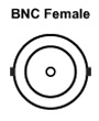
| Connector Type | BNC | ||||||
| General Data | |||||||
| Module Width | 1 PRO8 Slot | 2 Slots | |||||
| Laser Diode Connector | 9-pin D-Sub (f ) | 15-pin HDD-Sub (f ) | |||||
| Weight | <300 g | <500 g | <750 g | ||||
| Operating Temperature | 0 to 40 °C | ||||||
| Storage Temperature | -40 to +70 °C | ||||||
LDC8001-40のピン配置
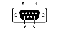
Dタイプメス型 DB9ピンコネクタ
| Pin | Connection |
|---|---|
| 1 | Output for Interlock and Status LASER ON/OFF |
| 2 | Monitor Diode Ground |
| 3 | Laser Diode Ground |
| 4 | Monitor Diode Input |
| 5 | Pin 1 Ground |
| 6 | Laser Diode Cathode (Measurement Input for Laser Diode Voltage) |
| 7 | Laser Diode Cathode (with Polarity AG) |
| 8 | Laser Diode Anode (with Polarity CG) |
| 9 | Laser Diode Anode (Measurement Input for Laser Diode Voltage) |
LDC8080のピン配置
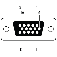
Dタイプメス型 HD15ピンコネクタ
| Pin | Connection |
|---|---|
| 1 | Laser Diode Cathode (with Polarity AG)* |
| 2 | Laser Diode Cathode (with Polarity AG)* |
| 3 | Laser Diode Ground* |
| 4 | Laser Diode Anode (with Polarity CG)* |
| 5 | Laser Diode Anode (with Polarity CG)* |
| 6 | Output for Interlock and Status LASER ON/OFF |
| 7 | Laser Diode Cathode (with Polarity AG)* |
| 8 | Laser Diode Ground* |
| 9 | Laser Diode Ground* |
| 10 | Laser Diode Anode (with Polarity CG)* |
| 11 | Laser Diode Cathode (Measurement Input for LD Voltage) |
| 12 | Monitor Diode Ground |
| 13 | Monitor Diode Input |
| 14 | Laser Diode Anode (Measurement Input for LD Voltage) |
| 15 | Ground for Pin 6 |
*レーザの接続には3つのピンすべて(1-2-7、3-8-9、4-5-10、3-8-9) を常にご使用ください。
LDC8001-40 ピン配列
Dタイプメス型 DB9ピンコネクタ
| Pin | Connection |
|---|---|
| 1 | Output for Interlock and Status LASER ON/OFF |
| 2 | Monitor Diode Ground |
| 3 | Laser Diode Ground |
| 4 | Monitor Diode Input |
| 5 | Pin 1 Ground |
| 6 | Laser Diode Cathode (Measurement Input for Laser Diode Voltage) |
| 7 | Laser Diode Cathode (with Polarity AG) |
| 8 | Laser Diode Anode (with Polarity CG) |
| 9 | Laser Diode Anode (Measurement Input for Laser Diode Voltage) |
外部変調
LDC8080 ピン配列
Dタイプメス型 HD15ピンコネクタ
| Pin | Connection |
|---|---|
| 1 | Laser Diode Cathode (with Polarity AG)* |
| 2 | Laser Diode Cathode (with Polarity AG)* |
| 3 | Laser Diode Ground* |
| 4 | Laser Diode Anode (with Polarity CG)* |
| 5 | Laser Diode Anode (with Polarity CG)* |
| 6 | Output for Interlock and Status LASER ON/OFF |
| 7 | Laser Diode Cathode (with Polarity AG)* |
| 8 | Laser Diode Ground* |
| 9 | Laser Diode Ground* |
| 10 | Laser Diode Anode (with Polarity CG)* |
| 11 | Laser Diode Cathode (Measurement Input for LD Voltage) |
| 12 | Monitor Diode Ground |
| 13 | Monitor Diode Input |
| 14 | Laser Diode Anode (Measurement Input for LD Voltage) |
| 15 | Ground for Pin 6 |
*レーザの接続には3つのピンすべて(1-2-7、3-8-9、4-5-10、3-8-9) を常にご使用ください。
LDC8000シリーズの電流コントローラには下記が付属します。
- LDC8000シリーズの電流コントローラーモジュール
- 操作マニュアル
| Posted Comments: | |
Alastair Curnock
(posted 2023-04-12 15:13:34.14) Hi
I am looking at a PRO8 system for LD & LED drive.
Would the LDC8010 be capable of driving LEDs with a forward volt drop of say 2.2V? hchow
(posted 2023-04-14 07:38:20.0) Dear Mr. Curnock, thank you for your feedback. Yes, in theory, you can use the LDC8010, so long as the compliance voltage of the LDC8010 (5V) is within the forward voltage drop of your LED. Which in this case, it is. Thank you. Changbao Ma
(posted 2021-06-24 13:21:28.24) I have many this cable and CAB420-15 from Thorlabs.
The plastic part of the screws on the connectors of this cable has really bad quality. It is too soft to survive a few times of screwing on and off using a screw driver. Suggest use all metal or high quality screws.
Same problem for CAB420-15. YLohia
(posted 2021-08-30 11:25:41.0) Thank you for your feedback. We are taking this into consideration and are exploring options to improve this. Volker Ebert
(posted 2020-07-28 11:46:06.983) if i modulate the LDC 8002 with an analog ramp signal e.g. from a signal generator .. is the voltage input first digitized and then added to the current source .. or remains the signal path from modulation input to laser current analog over the entire signal path
.. the manual says that the laser current can also be set via a digital interface .. does this option include the modulation input of the LDC .. ie. can i modulate the laser with the full 200 kHz band width via the digital interface ?
thanks for your answer on this bit more complicated questions !
best
Volker dpossin
(posted 2020-08-07 06:15:23.0) Dear Volker,
Thank you for your feedback. The signal remains analog over the entire signal path. As the digital inferface is designed to control the laser output current or power unfortunately it is not possible to apply modulation from there. I reached out to you in order to provide further help. craig.brideau
(posted 2017-05-09 22:30:45.657) Does the LDC8002 have a high enough compliance voltage to operate the LP488-SF20 and LP520-SF15 laser diodes? swick
(posted 2017-05-11 03:18:54.0) This is a response from Sebastian at Thorlabs. Thank you for the inquiry.
LP488-SF20 and LP520-SF15 require 7.5V and 8V forward voltage.
LDC8002 provides 5V compliance voltage, which is not enough to drive these laser diodes.
I will contact you directly for showing alternatives. |

 ズーム
ズーム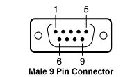
| CAB400 (9 Pin Male) Cable | |
|---|---|
| Pin # | Description |
| 1 | Interlock and Status LASER ON/OFF |
| 2 | Photodiodea |
| 3 | Laser Diode Ground |
| 4 | Photodiodeb |
| 5 | Ground for Pin 1 |
| 6 | Voltage Measurement Laser Diode Cathodec |
| 7 | Laser Diode Cathode (with Polarity Anode Grounded - AG) |
| 8 | Laser Diode Anode (with Polarity Cathode Grounded - CG) |
| 9 | Voltage Measurement Laser Diode Anodec |
| Calibration Service Item # | Compatible Modules |
|---|---|
| CAL-LDC8 | LDC8001, LDC8002, LDC8005, LDC8010, LDC8020, LDC8040, LDC8080 |
Thorlabs offers a recalibration service for the LDC8000 Series Laser Diode Current Control Modules. To ensure accurate measurements, we recommend recalibrating the devices every 24 months. The table to the right lists the modules for which the CAL-LDC8 recalibration service is available.
Requesting a Calibration
Thorlabs provides two options for requesting a calibration:
- Complete the Returns Material Authorization (RMA) form. When completing the RMA form, please enter your name, contact information, the Part #, and the Serial # of the item being returned for calibration; in the Reason for Return field, select "I would like an item to be calibrated." All other fields are optional. Once the form has been submitted, a member of our RMA team will reach out to provide an RMA Number, return instructions, and to verify billing and payment information.
- Enter the Part # and Serial # of the item that requires recalibration below and then Add to Cart. A member of our RMA team will reach out to coordinate return of the item for calibration. Should you have other items in your cart, note that the calibration request will be split off from your order for RMA processing.
Please Note: To ensure your item being returned for calibration is routed appropriately once it arrives at our facility, please do not ship it prior to being provided an RMA Number and return instructions by a member of our team.