 Products Home
傾斜エッジMTFターゲット
- Test Targets Evaluate Spatial Frequency Response of Imaging System
- Slant Edge, Ronchi Rulings and Sector Star Targets Available
- Grid Lens Slides Offered for Use with MTF Mapper Software
R2L2S2P1
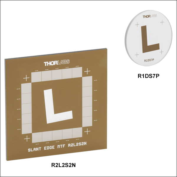
1.5" x 1.5" Positive Slant Edge Target
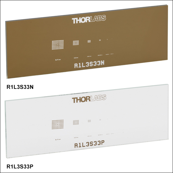
R1L3S33N
3" x 1" Negative MTF Mapper Lens Grid Slide
R1DS7N
Ø1" Negative Slant Edge Target
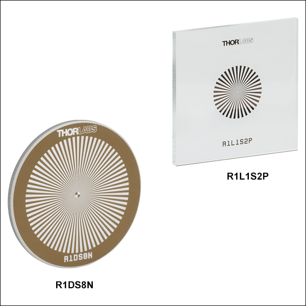
R1DS8N
Ø1" Negative Sector Star Target
R2L2S2N
2" x 2" Negative Slant Edge Target


Please Wait
Click to Enlarge
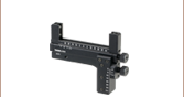
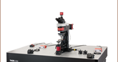
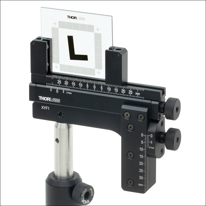
Figure 1.2 An R2L2S2P Slant Edge MTF Target Mounted in an XYF1 Test Target Positioner
Click to Enlarge
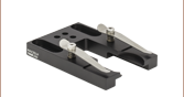
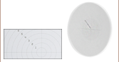
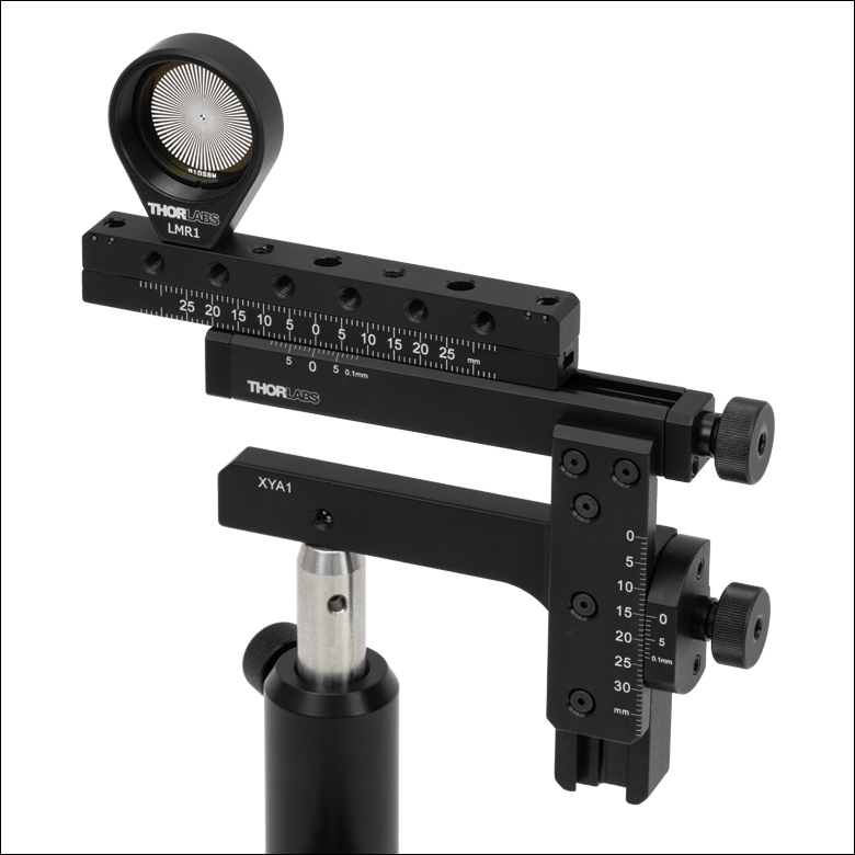
Figure 1.1 An R1DS8N Sector Star MTF Target Mounted in an XYA1 Test Target Positioner
Custom and OEM Test Targets
If you have a custom or OEM project that requires test targets, I would be happy to speak with you about our ability to customize the products sold on this page. For more information, I invite you to visit our Custom Capabilities tab or contact me directly to discuss your specific application.

Click to Enlarge
Examples of Test Target Customizations

Jason Williamson
Director of Business Development
Thorlabs Spectral Works
I look forward to hearing from you!
Features
- Determine Modulation Transfer Function (MTF) of an Imaging System
- ISO 12233:2014 Standard Compatible Patterns
- Evaluate Sharpness and Resolution of Imaging Systems
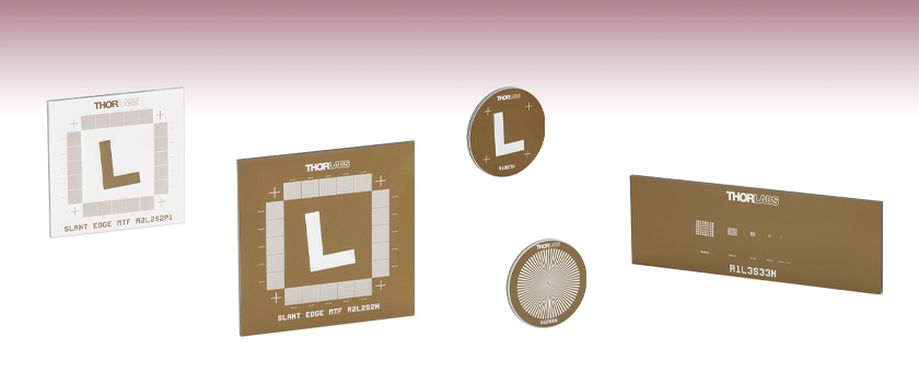
Thorlabs' MTF Targets allow the user to determine the spatial frequency response of an imaging system and its resolution via a slant edge pattern, sector star pattern, or Ronchi rulings. They are made by plating low-reflectivity, vacuum sputtered chrome on a soda lime glass substrate. Each pattern is manufactured using photolithography to allow for edge features to be resolved down to approximately 1 µm. The high edge sharpness provided by this method is essential when using the modulation transfer function (MTF), described below, to determine the performance of an imaging system.
Our MTF targets patterns are available as positive and negative targets. The positive targets consist of low-reflectivity, vacuum-sputtered chrome patterns plated on clear soda lime glass with a chrome background for high contrast in reflective applications, and are useful for front-lit applications. The negative targets use low-reflectivity chrome to cover the substrates, leaving the patterns clear, and work well in back-lit and highly illuminated applications. See the Graphs tab for spectral data of the materials used in these test targets.
Mounting
To mount our rectangular targets, Thorlabs offers the XYF1(/M) Test Target Positioning Mount (see Figure 1.2), while for our circular targets, Thorlabs recommends the XYA1(/M) Test Target Positioning Mount (see Figure 1.1). These mounts are capable of translating a target over a 50 mm (1.97") x 30 mm (1.18") area and secure a target using nylon-tipped setscrews. The mounts contain five 8-32 (M4) taps for six post-mountable orientations.
Modulation Transfer Function
The modulation transfer function (MTF) is used to determine the resolution and performance of an imaging system. Several kinds of targets exist to measure the MTF of a system, including sine wave targets, grill targets, and the slant edge target and sector star targets discussed here. For the slant edge method, a slant edge target, such as the R2L2S2P target, is imaged. The target consists of a distinct dark edge that is tilted at some angle, usually between one and five degrees. The edge should be produced using a method that will result in as distinct an edge as possible. In the case of the targets sold here, photolithography is used.
To calculate the MTF of the slant edge method, begin with the edge spread function (ESF), which is the intensity of the image as a function of spatial position as the edge is approached and crossed over (see Zhang et al., Proc. SPIE 8293, 2012). Due to imperfections in the imaging system, the ESF will be sloped on the border of the slanted edge, as opposed to being a perfect step function. Next, take the derivative of the ESF to produce the line spread function (LSF). Finally, take the Fourier transform of the LSF and normalize it to produce the MTF. The MTF, which will range from zero to one, can be plotted versus frequency (typically measured in cycles/mm). Frequencies with a corresponding MTF value close to one will be reproduced at approximately their original resolution. As the frequency increases, the MTF will fall to zero and the frequency will become indiscernible. The frequency that corresponds to an MTF of 0.5 is typically used as a benchmark to compare different imaging systems.
For the sector star, or Siemens star, method, a sector star target that consists of a binary image of dark and light spokes that increase in thickness as they radiate outwards is imaged. The MTF calculated for the sector star method is a multidirectional function able to measure spatial frequency in multiple directions, as opposed to the slant edge being only able to measure spacial frequency on its near-vertical or near-horizontal slanted edges. The multiple angles of the radiating pattern allow for calculating the multidirectional MTF (see Masaoka et al., Proc. SPIE 7537, 2010).
Various packages are available commercially for the calculation of the MTF using MATLAB® or ImageJ. One such package for MATLAB can be found here, while a package for ImageJ can be found here.
| Targets Selection Guide | ||||
|---|---|---|---|---|
| Resolution Test Targets | Calibration Targets | Distortion Test Targets | Slant Edge MTF Target | Stage Micrometers |
Click to Enlarge
This graph shows the transmission of the soda lime glass used in the positive and negative test targets.
Click to Enlarge
Spectral Curves of Reflective Test Targets
The large difference between the chrome (blue line) and low-reflectivity coated chrome (red line) in the visible region means that the positive reflective targets have high contrast between the pattern and the background.
Questions?
Need a Quote?
ご質問やお見積りのご要望は
お気軽に当社まで
ご連絡ください。
| Customization Parameters | ||
|---|---|---|
| Substrate Sizea | Min | 8 mm x 8 mm (5/16" x 5/16") |
| Max | 85 mm x 85 mm (3.35" x 3.35") | |
| Substrate Materials | Soda Lime Glass UV Fused Silica Quartz | |
| Coating Material | Chromeb Low-Reflectivity Chromec | |
| Coating Optical Density | ≥3d or ≥6e @ 430 nm | |
| Minimum Pinhole/Spot | Ø1 µm | |
| Minimum Line Width | 1 µm | |
| Line Width Tolerance | -0.25 / +0.50 µm | |
| Maximum Line Density | 500 lp/mm | |
カスタムおよび組み込み用途(OEM用途)向けテストターゲットとレチクル
当社のフォトリソグラフィ設計と製造能力により、様々なパターン素子を作ることが可能です。米国サウスカロライナ州コロンビアにある当社の施設では、テストターゲット、グリッド型歪テストターゲット、レチクルを製造しております。 これらは顕微鏡、イメージングシステム、光学アライメントのセットアップなど様々な用途に適用されてきました。
標準品のテストターゲットやレチクルに加え、ソーダ石灰基板、UV溶融石英(UVFS)基板、石英基板から8 mm x 8 mm~85 mm x 85 mmまでのカスタムクロムパターンのテストターゲット等をご提供可能です。基板はご用途に応じた形状に切断可能です。フォトリソグラフィによるコーティングプロセスにより、1 µmまでのクロムパターンが可能です。Figure 165C~165Jではサンプルパターンがご覧いただけます。またFigure 165A、165Bのようにポジパターンとネガパターンで作成可能です。
用途例
- エッチングレチクル
- グレースケールマスク
- 高分解能レチクル
- 測定用レチクル
- レクリエーション用スコープ
- ノッチ付きレチクル
- アイピース目盛
- 照明用十字レチクル
- オブストラクションターゲット
- 双眼鏡レチクル
カスタム仕様のテストターゲットやレチクルのお見積りについては、当社までお問い合わせください。
サンプルパターン
 Click to Enlarge
Figure 165D 同心円ストパターン
 Click to Enlarge
Figure 165C グリッドパターン
 Click to Enlarge
Figure 165B ネガパターンの十字線ターゲット
 Click to Enlarge
Figure 165A ポジパターンの十字線ターゲット
 Click to Enlarge
Figure 165J マイクロメーターパターン
 Click to Enlarge
Figure 165H ピンホールパターン
 Click to Enlarge
Figure 165G 分度器パターン
 Click to Enlarge
Figure 165F 目盛パターン
 Click to Enlarge
Figure 165E バイナリテストパターン
こちらでは当社のエンジニアが推奨するレチクル、テストターゲット、歪みターゲット、校正ターゲットの適切なクリーニング方法をご紹介いたします。
クリーニング手順
- できればポリビニルアルコール(PVA)製の清潔な濡れスポンジを使用し、食器用洗剤でレチクルやターゲットの正面と裏面を優しくこすります。
- 水ですすぎます。
- 清潔で乾燥した空気によるブローで乾かすか、清潔な面にレチクルやターゲットを置いて自然乾燥させます。
タオルや布、またはワイプを使用して拭くことはお勧めしません。汚れがまだ残る場合には、レチクルやターゲットを食器洗剤を混ぜた水溶液に1時間つけ置き、必要であればこれを繰り返します。
| Posted Comments: | |
Andrey Kuznetsov
(posted 2025-07-22 15:24:36.643) What is the photolithographic tolerance to cleaning solutions like: #1 acetone 60% and methanol 40%, #2 acetone ~100%, #3 methanol ~100%, #4 isopropanol ~100% solutions?
I've seen your cleaning tab with the detergent, water and dry air, but I'm wondering about these other chemical solutions and how they may affect the lithographic integrity. EGies
(posted 2025-07-24 04:40:44.0) Thank you for contacting Thorlabs. These cleaning solutions should be OK to use with the R2L2S2P. I have reached out to you directly regarding this. Yiğit Can Acar
(posted 2023-05-05 04:04:39.673) Dear Official,
I am writing this e-mail from “YUBA Teknoloji”, an optics company in Ankara, Turkey. I am also working as electrical engineer in this firm. In our company, we would like to build an MTF test system with a slanted edge target and off axis parabolic mirror. In your website, i examined your L shaped 5 degree slanted edge MTF target (https://www.thorlabs.com/newgrouppage9.cfm?objectgroup_id=7500) and found that this component can be useful for us. However, i have some important questions. First of all, is it avaible to conduct an experiment in visible and near infrared (VIS and NIR) spectrum with this Slant Edge MTF Target ? Since we are planning to illuminate this target from the front, we are going to need a well transparent material in our experiment and we need to know its transmission characteristics. In addition, which type of light source is compatible with this target ? We also would like to order additional mechanical components like XYF1 mount and other holders and post holders. Is it possible for you to come up with a complete suitable set and quotation proposal including Slant Edge Target, XYF1 mount and holders ?
Yours Sincerely,
Yiğit Can Acar. ksosnowski
(posted 2023-05-11 09:45:06.0) Hello, thanks for reaching out to Thorlabs. R2L2S2P uses our soda lime substrate, for which the data can be found on our main Resolution Target page (e.g. see R1DS1P). This maintains transmission throughout VIS and NIR ranges, and while we do not have a single light source for all scenarios, we have a variety of broadband lamps like SLS201 which you may consider for this range. I have reached out directly to discuss this application in further detail. Our sales team can also be reached directly via sales@thorlabs.com for a quote. ksosnowski
(posted 2023-05-11 09:45:06.0) Hello, thanks for reaching out to Thorlabs. R2L2S2P uses our soda lime substrate, for which the data can be found on our main Resolution Target page (e.g. see R1DS1P). This maintains transmission throughout VIS and NIR ranges, and while we do not have a single light source for all scenarios, we have a variety of broadband lamps like SLS201 which you may consider for this range. I have reached out directly to discuss this application in further detail. Our sales team can also be reached directly via sales@thorlabs.com for a quote. Martin Bordenave
(posted 2020-01-07 09:07:12.863) Dear Sir or Madam,
My name is Martin Diego Bordenave, I work as an optical engineering at Satellogic, an Argentinean, earth-observation company.
I would like to know is it is possible to buy a Slant Edge MTF Target similar to the R2L2S2P but instead of using a square substrate using a circular substrate of 2" diameter.
I look forward to hearing from you.
Best regards,
Dr. Martín Diego Bordenave
Telephone: +54 11 5219 0100
e-mail: martin.bordenave@satellogic.com YLohia
(posted 2020-01-07 12:33:17.0) Hello Martin, thank you for contacting Thorlabs. Custom items can be requested by emailing us at techsupport@thorlabs.com. I will reach out to you directly to discuss the possibility of offering this custom item. Ralf Noijen
(posted 2019-06-07 04:18:21.85) Dear Thorlabs,
I have two comments. My colleague had ordered the target which we received today. I inspected it under a microscope and found quite some damages, is that normal?
Secondly I found a link to a mtf measurement application for imageJ which is not working.
Can you please help.
BR
Ralf YLohia
(posted 2019-06-07 10:56:56.0) Hello Ralf, thank you for contacting Thorlabs. We are sorry to hear about the damaged item. This is certainly not normal -- I am reaching out to you directly to look into what sort of defects your piece has. Please use this link for the ImageJ package: https://imagej.nih.gov/ij/plugins/se-mtf/index.html. It is a non-Thorlabs website and it is working for on our end. dmiles
(posted 2017-01-09 13:36:40.047) The Slant Edge MTF Target looks very useful to us. It would help a lot if there were a scale image of it at normal incidence so we could design with the corner of the "L" at the focus of our system before we receive it. We are in a time crunch and our designer would be helped by that information. tfrisch
(posted 2017-01-10 09:37:29.0) Hello, thank you for contacting Thorlabs. we do have a CAD drawing that may be useful for your application. It can be found by clicking the documents icon below. I will send you a link directly as well. sebastien.avila
(posted 2015-01-07 12:08:20.28) Hello,
I would like to know if the clear parts of the target R2L2S2P are transparent or opaque white? Is it meant to be backlighted?
Should I use a diffuse source or a collimated source?
Thank you very much.
Sébastien AVILA
R&D VISION- France besembeson
(posted 2015-01-19 01:12:36.0) Response from Bweh at Thorlabs: The substrate is made from soda lime so transmission properties will be like that for soda lime in areas without the chrome. R2L2S2P is a positive target designed for front-lit applications. For MTF determination, you would typically image the slanted "L" so diffused or large diameter collimated source should be okay. |

 ズーム
ズーム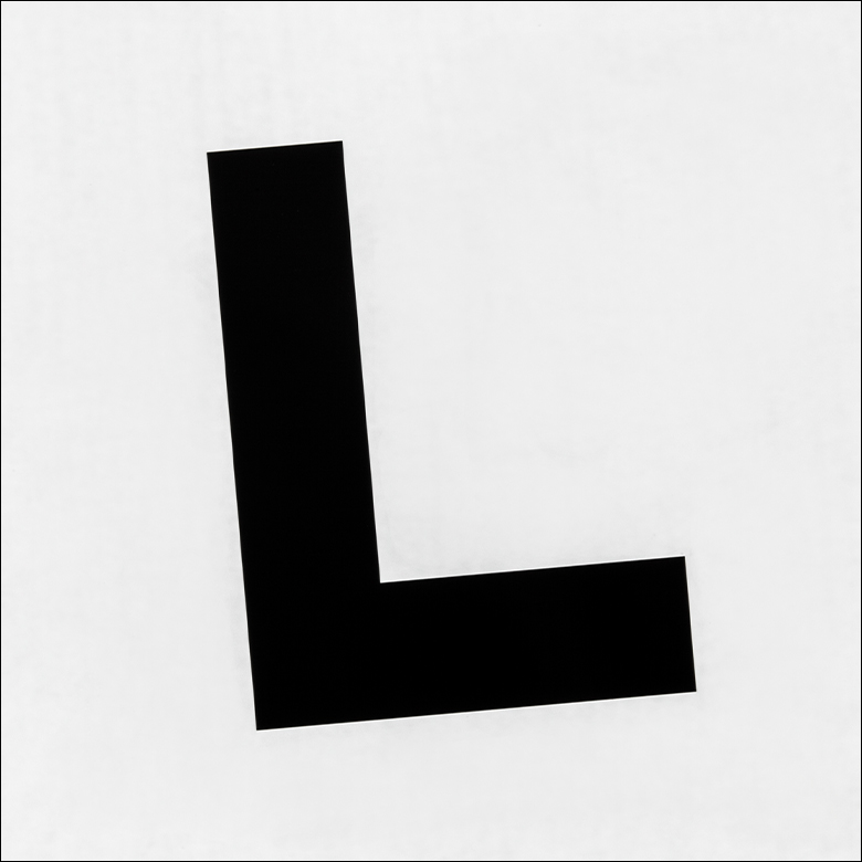
Click to Enlarge
Figure G2.1 Close Up the R2L2S2P Slant Edge Pattern
- Ø1" (25.4 mm), 1.50" x 1.50" (38.1 mm x 38.1 mm), and 2.00" x 2.00" (50.8 mm x 50.8 mm) Targets for Measuring Resolution Across an Image
- 5° Slanted, L-Shaped Pattern (ISO 12233 Compatible)
- Positive and Negative Targets Available
- Square Targets Also Offer 20 Ronchi Rulings, 10 lp/mm to 200 lp/mm
Thorlabs offers MTF test targets that allow the user to determine the spatial frequency response of an imaging system via a slant edge pattern. The slant edge pattern is L-shaped and tilted at 5° for compatibility with ISO 12233, and features a cross pattern at each of the four corners of the overall pattern for alignment. Our square targets also feature Ronchi rulings that can be used to determine the spatial frequency response. The Ronchi rulings include twenty individual rulings, each 5 mm x 5 mm in dimension and ranging in resolution from 10 line pairs per millimeter (lp/mm) to 200 lp/mm in 10 lp/mm intervals.
The positive targets consist of an OD3 low-reflectivity chrome pattern plated onto a clear substrate and are useful for front-lit and general applications. Alternatively, the negative targets use the same OD3 low-reflectivity chrome coating to cover the substrate, leaving the pattern itself clear, and work well in back-lit and highly illuminated applications.
| Key Specifications | ||||||
|---|---|---|---|---|---|---|
| Item # | R1DS7P | R1DS7N | R2L2S2P1 | R2L2S2N1 | R2L2S2P | R2L2S2N |
| Slant Edge Pattern | LRa Chrome | Clear | LRa Chrome | Clear | LRa Chrome | Clear |
| Background | Clear | LRa Chrome | Clear | LRa Chrome | Clear | LRa Chrome |
| Clear Aperture | Ø22.9 mm | Ø22.9 mm | 34.3 mm x 34.3 mm | 34.3 mm x 34.3 mm | 45.7 mm x 45.7 mm | 45.7 mm x 45.7 mm |
| Line Spacing Toleranceb | N/A | ±0.5 µm | ||||
| Smallest Ronchi Ruling Line Width | N/A | 2.5 µm | ||||
| Line Width Toleranceb | N/A | ±0.5 µm | ||||
| Crosshair Linewidth | 108 µm | 120 µm | 150 µm | |||
| Surface Flatness | ≤15 µm | |||||
| Substrate Thickness | 1.5 mm ± 0.2 mm | |||||
| Transmitted Wavefront Error | <λ at 633 nm | |||||
| Chrome Optical Densityc | ≥3.0 | |||||

 ズーム
ズーム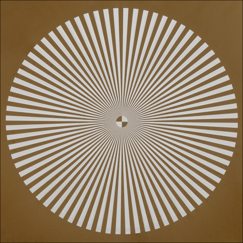
Click to Enlarge
Figure G3.1 Close Up of the R1DS8N Sector Star Pattern
- 1.00" x 1.00" (25.4 mm x 25.4 mm) Positive or Negative Sector Star Targets
- Ø1.00" (Ø25.4 mm) Negative Sector Star Target
- Determine the MTF and Resolution of an Optical System
- Low-Reflectivity, Vacuum-Sputtered Chrome on Soda Lime Glass
Thorlabs offers four 1.00" (25.4 mm) square targets and one Ø1.00" (Ø25.4 mm) target with sector star (also known as Siemens star) patterns. Two of the targets (Item #s R1L1S2P and R1L1S3P) have positive patterns, while the other three (Item #s R1DS8N, R1L1S2N, and R1L1S3N) have negative patterns.
The R1L1S2P and R1L1S2N targets have 36 bars over 360°, and the R1DS8N, R1L1S3P, and R1L1S3N targets have 72 bars over 360°. Most patterns have a 200 µm inner diameter and a 10 mm outer diameter, with the R1DS8N having a 1 mm inner diameter and 20 mm outer diameter. On the 36 bar targets, this provides resolutions from 1.2 lp/mm to 57.3 lp/mm, on the square 72 bar targets, resolutions from 2.3 lp/mm to 15 lp/mm, and on the circular 72 bar target, resolutions from 1.15 lp/mm to 23 lp/mm. The targets can be used to determine the resolution of an optical system by noting how close to the center of the pattern an optical system can resolve adjacent bars. For more information about sector star patterns being used to test system resolution, please see the Resolution Targets tab here.
| Item # | Pattern | Background | Surface Flatness |
Chrome Optical Density |
Pattern Outer Diameter |
Center Circle Diameter |
Number of Bars |
Resolution at Outer Diameter |
Resolution at Center Circle |
|---|---|---|---|---|---|---|---|---|---|
| R1DS8N | Clear | Low-Reflectivity Chrome |
≤15 µm | ≥3.0 at 430 nm | 20 mm | 1 mm | 72 Over 360° | 1.15 lp/mm | 23 lp/mm |
| R1L1S2P | Low-Reflectivity Chrome |
Clear | 10 mm | 200 µm | 36 Over 360° | 1.2 lp/mm | 57.3 lp/mm | ||
| R1L1S2N | Clear | Low-Reflectivity Chrome |
|||||||
| R1L1S3P | Low-Reflectivity Chrome |
Clear | 72 Over 360° | 2.3 lp/mm | 115 lp/mm | ||||
| R1L1S3N | Clear | Low-Reflectivity Chrome |

 ズーム
ズーム| Key Specifications | ||
|---|---|---|
| Item # | R1L3S33P | R1L3S33N |
| Pattern | LRa Chrome | Clear |
| Background | Clear | LRa Chrome |
| Clear Aperture | 68.6 mm x 22.9 mm | |
| Surface Flatness | ≤15 µm | |
| Substrate Thickness | 1.5 mm ± 0.2 mm | |
| Transmitted Wavefront Error | <λ at 633 nm | |
| Chrome Optical Densityb | ≥3.0 | |
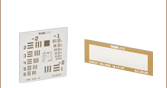
- 3.00" x 1.00" (76.3 mm x 25.4 mm) Rectangular MTF Mapper Slides
- Positive and Negative Targets Available
- Scaled MTF Mapper Lens Grids, 0.15 mm x 0.1 mm to 6 mm x 4 mm
Thorlabs offers two lens grid slides that are designed to measure the edge acuity of an imaging system using its MTF50 value, the spatial frequency at which the MTF falls to 50% of its maximum, which corresponds to the perceived sharpness of edges. The slides offer target grids of descending sizes of 6 mm x 4 mm, 3 mm x 2 mm, 1.5 mm x 1 mm, 0.75 mm x 0.5 mm, 0.3 mm x 0.2 mm, and 0.15 mm x 0.1 mm that can be used to characterize imaging systems. The R1L3S33N negative slide is fabricated from the deposition of a dark low-reflectivity chrome pattern on a 3.00" x 1.00" x 0.06" (76.3 mm x 25.4 mm x 1.5 mm) soda lime glass substrate, while the R1L3S33P positive slide consists of the same low-reflectivity chrome pattern plated onto a clear substrate.
These slides have been designed for use with the third party open source MTF Mapper software available here, and will be recognized automatically by the software. They may be used with software other than MTF Mapper, but additional adjustment may be required.