 Products Home
InGaAs増幅フォトディテクタ、ファイバー結合型
- Wavelength Range from 950 - 1650 nm
- Fixed or Switchable Gain Versions
- Bandwidths Up to 1500 MHz
- High Signal-to-Noise Ratio
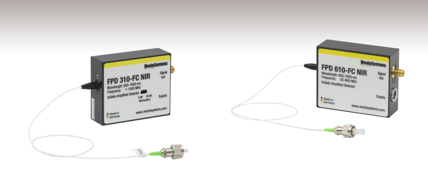
FPD610-FC-NIR
Fixed Gain
600 MHz Max Bandwidth
FPD310-FC-NIR
Switchable Gain
1500 MHz Max Bandwidth

Please Wait
用途例 |
| FPD310-FC-NIR |
|
| FPD510-FC-NIR & FPD610-FC-NIR |
|
特長
- 増幅器を内蔵
- ファイバ結合型モジュール、ポスト取付け用のM4タップ穴付き
- 最小負荷抵抗(推奨):50 Ω
- ACアダプタが付属
当社では近赤外の波長域に感度のあるファイバ結合型のInGaAs増幅フォトディテクタをご用意しております。これらの高速応答ディテクタは、高速レーザーパルス、低光量信号、あるいは断続光などの検出に適しています。すべてのディテクタに電源が付属します。
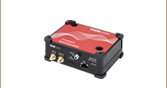
FPD310-FC-NIR
高感度・超高速のPINフォトディテクタFPD310-FC-NIRは、高利得・高帯域幅で、極めて早い立ち上がり時間と高い信号対雑音比が得られるよう最適化されています。このフォトディテクタは、InGaAs PINフォトダイオードに高利得・低ノイズのRF増幅器が付いており、使い易い製品になっています。利得は2段階の切り替えが可能なため、多くの用途に合わせて性能を発揮できます。コンパクトな設計により、製品への組み込みが容易です。国内用には動作確認済みの15V電源が付属します。このディテクタには、光入力用FC/APCコネクタの付いたSMF28のピグテールが付いています。
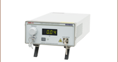
FPD510-FC-NIR&FPD610-FC-NIR
高感度・超高速のPINフォトディテクタ FPD510-FC-NIRおよびFPD610-FC-NIRは、それぞれ250 MHzおよび600 MHzまでの周波数範囲において、低光量の光ビート信号やパルス形状を検出するうえで最大の信号対雑音比が得られるように最適化されています。 これらのフォトディテクタは、InGaAs PINフォトダイオードに高利得・低ノイズのトランスインピーダンス増幅器が付いており、使い易い製品になっております。DC結合デバイスであるFPD510-FC-NIRおよびFPD610-FC-NIRの3 dB帯域幅は、それぞれ200 MHzおよび500 MHzです。コンパクトな設計により、製品への組み込みが容易です。国内用には動作確認済みの15V電源が付属します。 これらのディテクタには、光入力用FC/APCコネクタの付いたSMF28のピグテールが付いています。
自由空間光向けのInGaAsフォトディテクタについてはこちらをご覧ください。
| Item # | FPD310-FC-NIR | FPD510-FC-NIR | FPD610-FC-NIR |
|---|---|---|---|
| Material | InGaAs | ||
| Optical Input | SMF28 Pigtail with FC/APC | ||
| Spectral Range | 950 - 1650 nm | ||
| Saturation Limit | < 200 µW | < 100 µW | < 100 µW |
| Damage Threshold | 2 mW | 3 mW | 3 mW |
| Frequency Range | 1 - 1500 MHz | DC - 250 MHz | DC - 600 MHz |
| 3 dB Bandwidth | 5 - 1000 MHz | DC - 200 MHz | DC - 500 MHz |
| Rise Time | 0.5 ns | 2 ns | 1 ns |
| Gain (fs Pulsed Input)a | Setting 1: 2 x 10⁴ Vpp/W Setting 2: 2 x 10³ Vpp/W | 1.5 x 10⁵ Vpp/W | 2 x 10⁶ Vpp/W |
| Gain (CW Input)a | Setting 1: 2.5 x 10³ V/W Setting 2: 2.5 x 10² V/W | 5 x 10⁴ V/W | 5 x 10⁵ V/W |
| Dark State Noise Level | -100 dBm/Hz1/2 (Up to 5 MHz) -130 dBm/Hz1/2 (5 to 1500 MHz) | -110 dBm/Hz1/2 (Up to 5 MHz) -135 dBm/Hz1/2 (5 to 250 MHz) | -80 dBm/Hz1/2 (Up to 5 MHz) -100 dBm/Hz1/2 (5 to 600 MHz) |
| NEP (Calculated) | 12.0 pW/Hz1/2 | 3.0 pW/Hz1/2 | 5.6 pW/Hz1/2 |
| Output Impedance | 50 Ω | 50 Ω | 50 Ω |
| Output Coupling | AC | DC | DC |
| Output Signal | ~1 V | 0 - 1 V | 0 - 1 V |
| Supply Voltage / Max. Current Consumption | +12 VDC / 100 mA | +12 VDC / 50 mA -12 VDC / 20 mA | +5 VDC / <250 mA -12 VDC / <50 mA |
| Typical Performance Graphs | |||
| Output Connector | SMA Female | ||
| Operating Temperature | 10 to 40 °C | ||
| Storage Temperature | -20 to +85 °C | ||
| Storage Humidity (RH) | 10% to 90% | ||
| Device Dimensions | 60 mm x 50 mm x 20 mm (2.4" x 2.0" x 0.79") | ||
FPDシリーズディテクタ
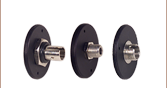
信号出力:SMAメス型
(フォトディテクタ)
オシロスコープやRFスペクトラムアナライザなどのモニタ装置に50Ωインピーダンスで接続できます。
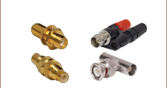
メス型(電源ケーブル)
オス型電源コネクタ(フォトディテクタ)
※国内用には動作確認済みの15v電源が付属します
パルスレーザ:パワーとエネルギーの計算

パルスレーザからの放射光が、使用するデバイスや用途に適合するかどうかを判断する上で、レーザの製造元から提供されていないパラメータを参照しなければならない場合があります。このような場合、一般には入手可能な情報から必要なパラメータを算出することが可能です。次のような場合を含めて、必要な結果を得るには、ピークパルスパワー、平均パワー、パルスエネルギ、その他の関連するパラメータを必要とすることがあります。
- 生物試料を損傷させないように保護する
- フォトディテクタなどのセンサにダメージを与えることなくパルスレーザ光を測定する
- 物質内で蛍光や非線形効果を得るために励起を行う
パルスレーザ光のパラメータはFigure 170AおよびTable 170Bに示します。参照用として、計算式の一覧を以下に示します。資料を ダウンロードしていただくと、これらの計算式のほかに、パルスレーザ光の概要、異なるパラメータ間の関係性、および計算式の適用例がご覧いただけます。
計算式 | ||||
 | 、 |  | ||
 | ||||
 | ||||
 | ||||
平均パワーから算出するピークパワー、ピークパワーから算出する平均パワー : | ||||
 | 、 |  | ||
| 平均パワーおよびデューティーサイクルから算出するピークパワー*: | ||||
 | *デューティーサイクル( ) はレーザのパルス光が放射されている時間の割合です。 ) はレーザのパルス光が放射されている時間の割合です。 | |||
Click to Enlarge
Figure 170A パルスレーザ光の特性を記述するためのパラメータを、上のグラフとTable 170Bに示します。パルスエネルギ (E)は、パルス曲線の下側の黄色の領域の面積に対応します。このパルスエネルギは斜線で表された領域の面積とも一致します。
| Table 170B パルスのパラメータ | |||||
|---|---|---|---|---|---|
| パラメータ | シンボル | 単位 | 説明 | ||
| パルスエネルギ | E | ジュール[J] | レーザの1周期中に放射される1パルスの全放射エネルギ。 パルスエネルギはグラフの黄色の領域の面積に等しく、 これは斜線部分の面積とも一致します。 | ||
| 周期 | Δt | 秒 [s] | 1つのパルスの開始から次のパルスの開始までの時間 | ||
| 平均パワー | Pavg | ワット[W] | パルスとして放射されたエネルギが、1周期にわたって 均一に広がっていたと仮定したときの、 光パワーの大きさ(光パワー軸上の高さ) | ||
| 瞬時パワー | P | ワット[W] | 特定の時点における光パワー | ||
| ピークパワー | Ppeak | ワット [W] | レーザから出力される最大の瞬時パワー | ||
| パルス幅 |  | 秒 [s] | パルスの開始から終了までの時間。一般的にはパルス形状の 半値全幅(FWHM)を基準にしています。 パルス持続時間とも呼ばれます。 | ||
| 繰り返し周波数 | frep | ヘルツ [Hz] | パルス光が放射される頻度を周波数で表示した量。 周期とは逆数の関係です。 | ||
計算例
下記のパルスレーザ光を測定するのに、最大入力ピークパワーが75 mW
のディテクタを使用するのは安全かどうかを計算してみます。
- 平均パワー: 1 mW
- 繰り返し周波数: 85 MHz
- パルス幅: 10 fs
1パルスあたりのエネルギは、

と低いようですが、ピークパワーは、

となります。このピークパワーはディテクタの
最大入力ピークパワーよりも5桁ほど大きく、
従って、上記のパルスレーザ光を測定するのに
このディテクタを使用するのは安全ではありません。
| Posted Comments: | |
CAN FANG
(posted 2024-05-17 05:29:06.623) Dear Thorlabs Support Team,
I hope this message finds you well.
I am writing to bring to your attention an issue that I have encountered with two of our Thorlabs PDA8GS devices. Both units were previously functioning properly, but we recently experienced unexpected behavior with their outputs.
The first unit, when connected to an oscilloscope, consistently outputs -1V regardless of whether there is optical input or not. Similarly, the second unit outputs -1.5V under the same conditions.
We have tried troubleshooting the issue by checking the connections and power supplies, but the problem persists. We would greatly appreciate your guidance on any possible solutions or steps we can take to rectify this problem.
Thank you for your attention to this matter. I look forward to your prompt response and assistance in resolving this issue.
Best regards,
Can Fang ksosnowski
(posted 2024-06-07 02:24:56.0) Hello Can Fang, thanks for reaching out to Thorlabs. The PDA8GS were checked during production to make sure the DC offset was as close to zero as possible. Unfortunately, offsets this large likely mean that the amplifier is damaged. This detector is very sensitive and can easily break if any of the max ratings are exceeded. The amplifier and photodiode pigtail in this detector were a single module which is no longer produced by the OEM and we had to discontinue this detector. We no longer have any modules to replace on damaged units sadly. We recently released RXM15EF as a replacement for this. The RXM15EF also has a fiber-coupled input, transimpedance amplifier, and a higher bandwidth. I have reached out directly to discuss this further. Srikanth G
(posted 2024-01-10 01:35:07.107) May I know minimum bend radius (long term; few years) for the fiber pigtail of FPD610-FC-NIR? ksosnowski
(posted 2024-01-10 01:52:07.0) Hello Srikanth, thanks for contacting Thorlabs. FPD610-FC-NIR uses SMF28 fiber for which the long term bend radius is 16mm for a short length like this detector's pigtail. Sowmendran P
(posted 2023-02-01 21:13:59.35) Hello,
We are reviewing product specification of FPD610-FC-NIR to use for EDFA characterization mesurement in our R&D lab.
Kindly help us clarify following queries,
1> PArameter MAx-Gain menioned is the OE coverrtion gain?
2> Conversion gain mentioned is 2E6v/W does it mean that for every microwatt of optical input change i would get 2v change int he output?
3> Also specification for output signal is menioned as 0~1V does it mean that max output is only 1V? how can we corelate this parameter with conversion gain? ksosnowski
(posted 2023-02-10 12:58:06.0) Thanks for reaching out to Thorlabs. The values listed in V/W are indeed Opto-Electric Conversion Gains. The conversion gain relates input optical power to output electrical power, though the output voltage will saturate at 1V, yielding a nonlinear increase in output with respect to increasing optical input past this point. Saturation can lead to damage on the photodiode/amplifier. I have reached out directly to discuss this further. user
(posted 2021-07-06 22:40:16.943) Hi,
When we turn on the PDA8GS we see a DC voltage of -2.5V on the oscilloscope with 50-ohm termination. What might be the reason for this behavior? The device seems to be working fine when plugged into a spectrum analyzer. YLohia
(posted 2021-08-27 02:45:08.0) Hello, thank you for contacting Thorlabs. It is very strange that you have such a large offset at the oscilloscope. Do you have a terminating resistance at the O-scope or just using the native impedance of the port? What does the signal look like if there is no light incident on the device? is that where you see the large offset? If you switch to Hi-Z coupling on your O-scope does anything change? What kind of spectrum analyzer are you using? Is this a brand new PDA8GS? user
(posted 2019-05-09 13:43:00.173) I have similar question that was posed to ThorLabs in past. Generally the detectors with GHz response have lower frequency cut-off of few 10s of kHz. Also AC coupled versions do not detect CW component. PDA8GS seems to be an exception. Can PDA8GS display DC and few kHz pulse trains (with pulses of slow rise /fall times few ns) without distortion? If a signal has DC and AC components, Can PDA8GS be used detect pulsed signal and its DC background (CW component)?
Below is similar question from past from someone else for your ready reference.
-Srikanth
kedves (posted 2017-05-11 15:07:06.75)
Dear Thorlabs, let me inquire about the frequency characteristics of PDA8GS. Is the transfer function over the whole frequency range DC-9.5 GHz smooth? I am asking this because we have fast amplified photoreceivers of another manufacturer which have a crossover region (at about 25-100 KHz) between the DC and AC responses leading to a distorted output signal to e.g. a step function input. What is the response of this detector to a step function? Is there any visible transition between the DC and high frequency ranges? Thanks
nbayconich (posted 2017-06-07 05:03:14.0)
Thank you for contacting Thorlabs. We are currently looking into measuring the bandwidth frequency characteristics of the PDA8GS. A techsupport representative will contact you directly with more information. asundararaj
(posted 2019-05-09 07:27:47.0) Thank you for contacting Thorlabs. The PDA8GS is a DC coupled detector and hence, it can detect both CW and and ~kHz pulsed components of the signal. I have contacted you directly via email to discuss this further. minowa
(posted 2018-09-24 06:14:47.367) Hi, could you provide the information about the NEP of PDA8GS? YLohia
(posted 2018-09-24 01:17:12.0) Hello, thank you for contacting Thorlabs. The dark current, at 25°C, is typically <10nA, and at 55°C is typically <50nA. The NEP for the fiber-optic receiver is:
NEP (rms)
1.5uW typical @ 1310nm
3.0uW maximum @ 1310nm
2.5uW typical @ 850nm
5.0uW maximum @ 850nm
Recently, we performed a preliminary test with 1550nm, and found that the input referred noise = 1.5uW rms (with 9.5GHz bandwidth).
Assuming a white noise distribution over the 9.5GHz bandwidth, this implies NEP = 15pW/rt-Hz. These numbers then scale inversely with responsivity at other wavelengths.
Please note that this only sample data and is not necessarily representative of our current units. These values presented are not a guaranteed performance. kedves
(posted 2017-05-11 15:07:06.75) Dear Thorlabs, let me inquire about the frequency characteristics of PDA8GS. Is the transfer function over the whole frequency range DC-9.5 GHz smooth? I am asking this because we have fast amplified photoreceivers of another manufacturer which have a crossover region (at about 25-100 KHz) between the DC and AC responses leading to a distorted output signal to e.g. a step function input. What is the response of this detector to a step function? Is there any visible transition between the DC and high frequency ranges? Thanks nbayconich
(posted 2017-06-07 05:03:14.0) Thank you for contacting Thorlabs. We are currently looking into measuring the bandwidth frequency characteristics of the PDA8GS. A techsupport representative will contact you directly with more information. makarov
(posted 2016-05-26 14:11:44.267) PDA8GS actually dies if the optical power rating is exceeded. This was a surprise to us. The maximum rating is 1 mW CW. We did not pay attention initially, because we thought the front-end photodied surely takes much more that 1 mW to get physically damaged, and what else could go wrong? It has turned out, the RF amplifier dies. Our units just came back from a lengthy and costly repair. I with it were stated in the spec sheet that damage to the RF amplifier will result from exceeding the optical power.
We have similar amplified photodetectors from LeCroy (OE455/555) and they do not die from optical overload, even though they get saturated at less than 1 mW just as this Thorlabs photodetector. besembeson
(posted 2016-06-01 05:33:43.0) Response from Bweh at Thorlabs USA: This is actually a failure of the sensor material itself. To operate at these high speeds, the active area needs to be very small since the photodiode capacitance is directly correlated to active area. This is the limiting factor for electrical bandwidth. In this case, the fiber inserts against a ball lens that focuses all the light onto this very small active area sensor. The material damage threshold can easily be exceeded. Usually it looks like a very large dark current to the electronics where the gain is usually enough to saturate the output to the voltage rail. Since this is an integrated PD and amplifier package, the complete module needs to be replaced as a result of this - reason for the repair being more expensive than imagined. |