 Products Home
パワー&エネルギーメーターインターフェイス、外部読み出しタイプ
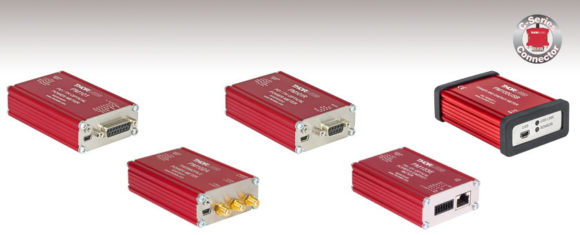
- Compact Power Meter Interfaces with Various Output Connection Options
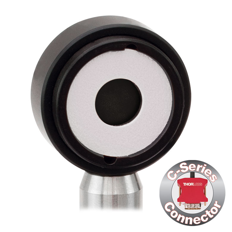
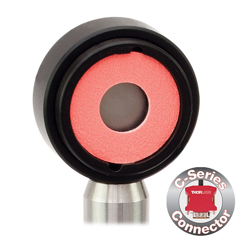
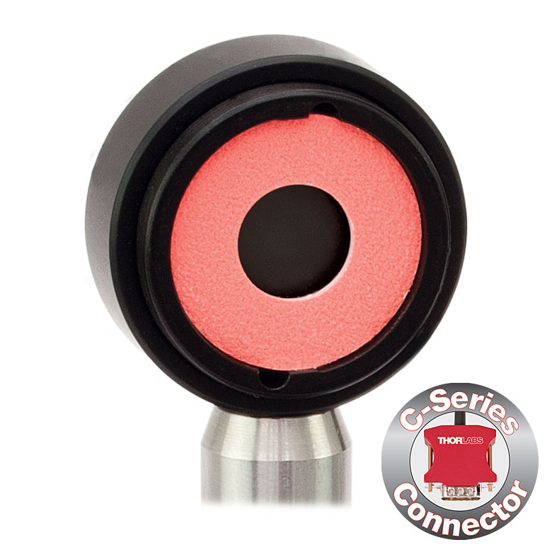
- Red C-Series Connector for Quick Sensor Exchange
- Ideal for Manufacturing Environments
PM101
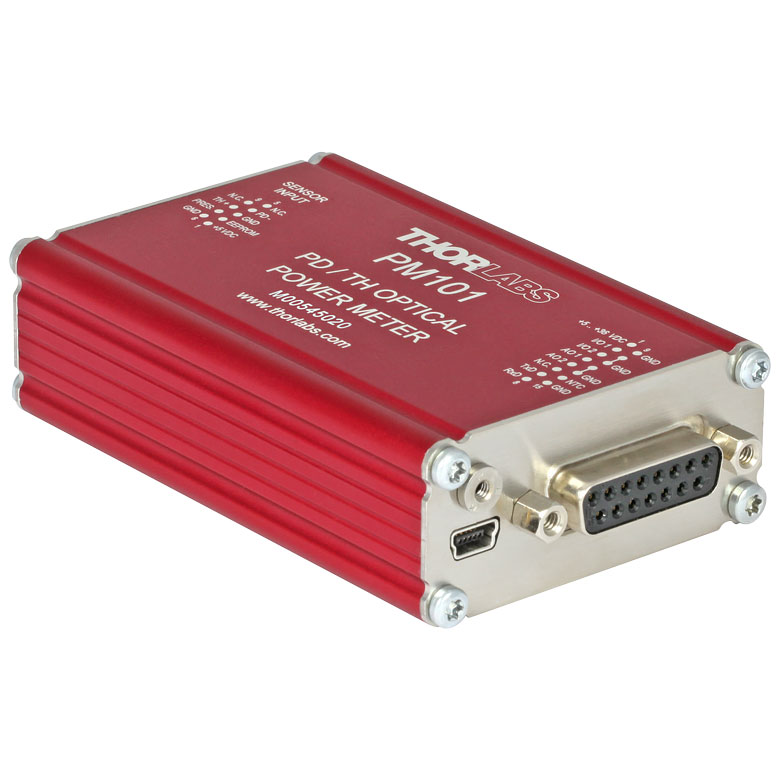
Photodiode and Thermal Power Sensor Interface with USB, RS232, and Analog Operation
Compatible with C-Type Sensors (Not Included with Console)
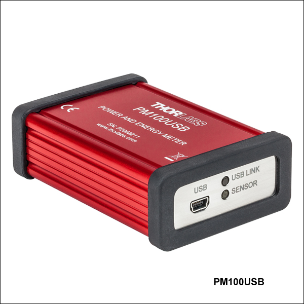
PM100USB
Power and Energy Sensor Interface with USB Operation
PM102A
Thermal Power and Position Sensor Interface with USB and Analog SMA Operation
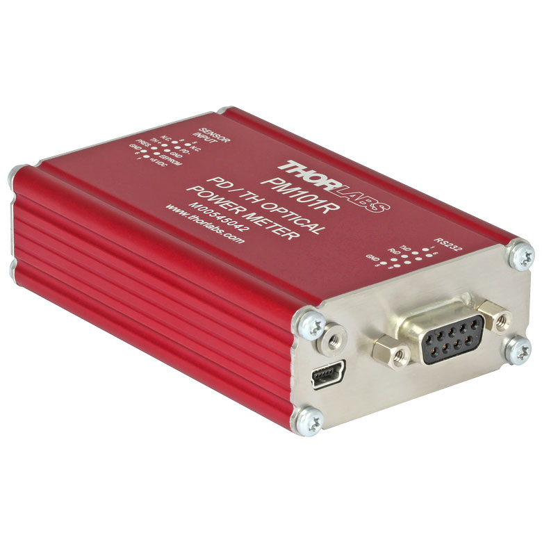
PM101R
Photodiode and Thermal Power Sensor Interface with USB and RS232 Operation
PM103E
Photodiode Power and Pyroelectric Energy Sensor Interface with Ethernet, RS232, and Analog Operation


Please Wait
| Power Meter Selection Guide |
|---|
| Sensors |
| Photodiode Power Sensors |
| Thermal Power Sensors |
| Thermal Position & Power Sensors |
| Pyroelectric Energy Sensors |
| Power Meter Consoles |
| Digital Handheld Console |
| Analog Handheld Console |
| Touchscreen Handheld Console |
| Dual-Channel Benchtop Console |
| Complete Power Meters |
| Power Meter Bundles |
| Wireless Power Meters with Sensors |
| Compact USB Power Meters |
| Field Power Meters for Terminated Fibers |
| USB Interfaces, External Readout |
Click to Enlarge
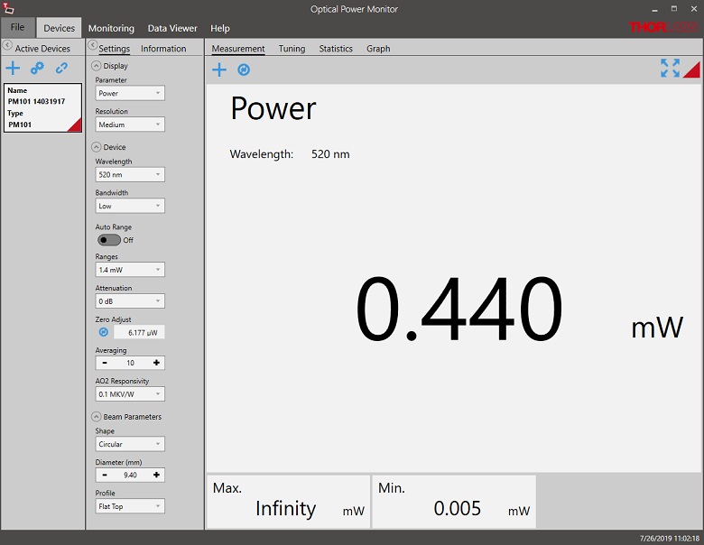
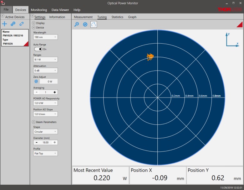
ソフトウェアOptical Power MonitorのGUI:パワー測定
Click to Enlarge
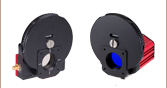
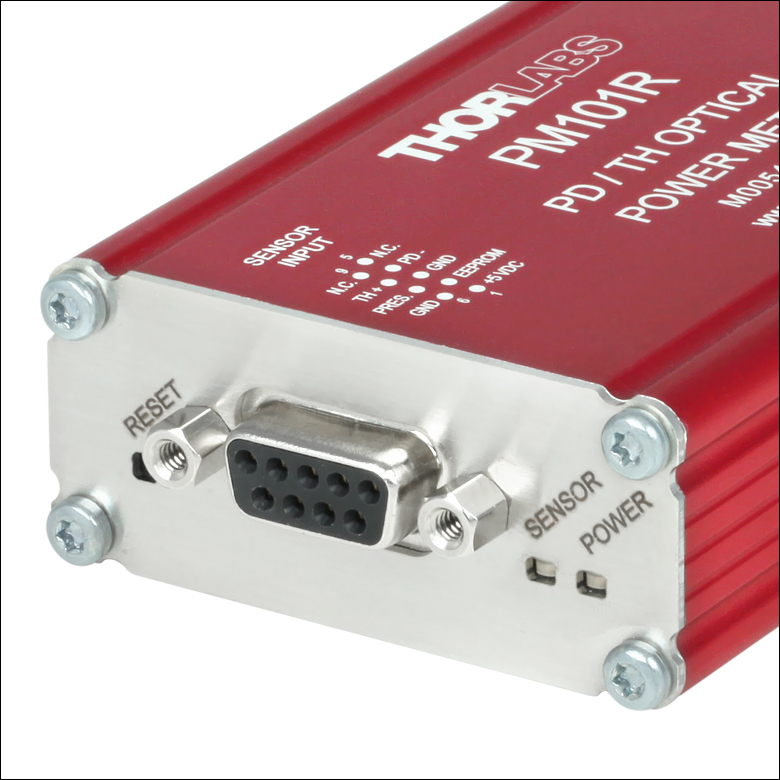
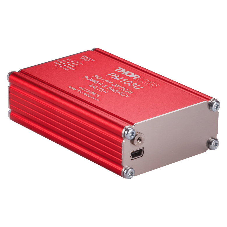
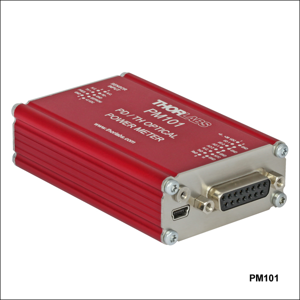
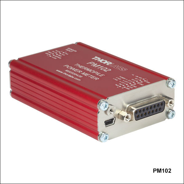
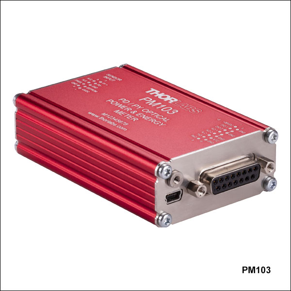
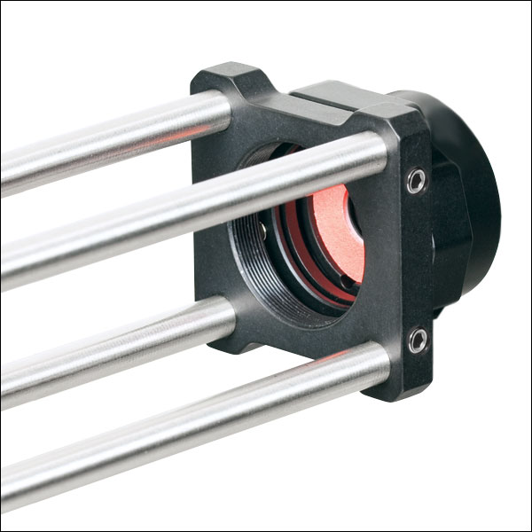
すべてのパワーメーターインターフェイスには入力用コネクタとしてDE-9が付いています。また、PM101、PM102およびPM103シリーズには、LEDのステータスインジケータと、インターフェイスを再起動するためのリセットボタンも付いています。
特長
- パワーメーターシステムのPC制御を可能にするコンパクトなインターフェイス
- 当社のCシリーズセンサに対応
- PM101シリーズ:フォトダイオードパワーセンサ、サーマルパワーセンサに対応
- PM102シリーズ:サーマルパワーセンサ、サーマル位置&パワーセンサに対応
- PM103シリーズ:フォトダイオードパワーセンサ、焦電エネルギーセンサに対応
- PM100USB:フォトダイオードパワーセンサ、サーマルパワーセンサ、焦電エネルギーセンサに対応(型番ES408Cを除く)
- PCソフトウェアOptical Power Monitorをご用意(詳細は「ソフトウェア」タブを参照)
こちらのインターフェイスを使用することで、取り付けたセンサとPCまたは他の外部制御ユニットとの通信が可能になります。これらは外部デバイスにより制御するか、またはアナログ出力を利用して単独で使用するように設計されているため、コントローラやディスプレイ画面はありません。
PM101シリーズは当社Cシリーズのフォトダイオードパワーセンサとサーマルパワーセンサに対応し、PM102シリーズは当社Cシリーズのサーマルパワーセンサとサーマル位置&パワーセンサに対応します。PM103シリーズは当社Cシリーズのフォトダイオードパワーセンサと焦電エネルギーセンサに対応します。これらのインターフェイスでは、制御やデジタル信号の読み出し方法として、USB 2.0、RS232、UART、アナログ出力、イーサネットなど、モデルによって幾つかの選択肢がございます。PM101およびPM102シリーズの読み出し速度が最大1 kS/s(キロサンプル/秒)であるのに対し、PM103シリーズはそれを大きく上回る100 kS/sの読み出し速度でデータを取得できます。インターフェイスPM100USBの制御とデジタル信号読み出しはUSB 2.0経由でのみ可能ですが、このインターフェイスは当社のCシリーズフォトダイオードパワーセンサ、サーマルパワーセンサ、および焦電エネルギーセンサ(型番ES408Cを除く)に対応しています。型番固有の技術データの概要は、下の表および「モデルの比較」タブをご覧ください。
これらのコンパクトなインターフェイスの筐体は、アルミニウム製クランプECM100またはECM225を用いてポストに取り付けることができます。また、プラスチック製クランプEPS225を用いて複数のユニットを積み重ねることもできます。
センサの互換性
当社のパワーセンサとエネルギーセンサのラインナップについては「センサの選択」タブまたは下記をご覧ください。このページでご紹介しているすべてのインターフェイスはホットスワップが可能であり、ユニットの電源をオンにしたままセンサを交換することができます。
PC制御
パワーメーターインターフェイスに接続されたセンサは、PCとOPMソフトウェア(詳細は「ソフトウェア」タブ参照)を用いて制御できます。このプログラムでは様々な数値パラメータを表示する設定画面を提供しており、ユーザはパワー測定またはエネルギー測定、その最小値や最大値、およびその単位などを選択することができます。このGUIは最大8台までのパワーメータのデータロギング機能を有し、グラフや表形式で表示することができます。また、予め設定した期間における測定値の統計評価もヒストグラムで表示します。データは.csvファイルとして保存できます。他社製のソフトウェアやカスタマイズされたアプリケーションと統合するためのドライバーセットもご提供しています。
システム設計
帯域幅として20 Hzまたは100 kHzのどちらかを選択ができるため、フォトダイオードパワーセンサを使用して行う個別の測定作業に対する柔軟性や適用性が向上しています。広帯域幅を選択するとパルス検出用に適しており、狭帯域幅を選択するとより正確さが要求される用途に適しています。Cシリーズのサーマルセンサを使用した場合、インターフェイスは各センサのコネクタに保存されている熱時定数の情報を適用することで、システムの応答時間を最小化することができます。
ファイバ用フォトダイオードパワーメータ
小型のS15xCシリーズファイバ用フォトダイオードパワーセンサをPM101x、PM103xまたはPM100USBパワーメーターインターフェイスに直接接続して、コンパクトな単一ユニットのファイバ用パワーメータとして使用することができます。ケーブルを動かすことに対する取り扱い制限が無くなるので、リモート操作を必要とする複数のセンサを用いる用途に適しています。これらのファイバ用センサはFC/PC、FC/APC、LC、SC、STファイバーコネクタ用のアダプタに対応します。なお、これらは当社のPM102シリーズのインターフェイスには対応していません。
再校正サービス
当社のサーマルパワー&フォトダイオードパワーセンサ、サーマルパワー&位置センサ、焦電エネルギーセンサ、およびパワーメーターインターフェイスについては、再校正サービスをご提供しております。当社ではセンサとインターフェイスをセットで再校正されることをお勧めしておりますが、単体で再校正を行うことも可能です。再校正サービスの詳細につきましては、当社までお問い合わせください。
センサのアップグレードサービス
当社のセンサおよびインターフェイスは、それぞれ旧型のパワーメーターコンソールおよびセンサーヘッドには対応していません。お客様所有の旧型のセンサを新しいパワーメーターコンソールやインターフェイスと接続して使用されたい場合には、センサのアップグレードサービスの利用をお勧めします。注:アップグレードされたセンサは、旧型のパワーメーターコンソールには対応しなくなります。また、新しいセンサで古いコンソール用に変換されたものは、このページに掲載されているパワーメーターインターフェイスには対応しません。詳細は当社までお問い合わせください。
| Quick Comparisona | ||||||||||||
|---|---|---|---|---|---|---|---|---|---|---|---|---|
| Item # | PM101 | PM101A | PM101R | PM101U | PM102 | PM102A | PM102U | PM103 | PM103A | PM103E | PM103U | PM100USB |
| USB Operation |  | | | | | | | | | - | | |
| Autonomous Operation with Analog Output | | | - | - | | | - | | | | - | - |
| RS232 Operation | | - | | - | | - | - | | - | | - | - |
| UART Operation | | - | - | - | | - | - | | - | - | - | - |
| Ethernet Operation | - | - | - | - | - | - | - | - | - | | - | - |
| Non-Volatile Memory | | | | | | | | | | | | - |
| Configurable as Trigger Input/Output | - | - | - | - | - | - | - | | | | - | - |
| Sensor Compatibility | ||||||||||||
| Photodiode Power | | | | | - | - | - | | | | | |
| Thermal Power | | | | | | | | - | - | - | - | |
| Thermal Position & Power | - | - | - | - | | | | - | - | - | - | - |
| Pyroelectric Energy | - | - | - | - | - | - | - | | | | | b |
| Sensor Compatibility | ||||
|---|---|---|---|---|
| Item # | PM101 Series | PM102 Series | PM103 Series | PM100USB |
| Sensor Compatibility | ||||
| Compatible Sensor Typesa | Photodiode Power and Thermal Power | Thermal Power and Thermal Position & Power | Photodiode Power and Pyroelectric Energy | Photodiode Power, Thermal Power, and Pyroelectric Energyb |
| Max Photodiode Sensor Current | 5 mA | N/A | 10 mA | 5 mA |
| Max Thermal Sensor Voltage | 1 V | 1 V | N/A | 1 V |
| Max Thermal Position Sensor Voltage | N/A | 1 V | N/A | N/A |
| Max Pyroelectric Sensor Voltage | N/A | N/A | 200 V | 100 V |
| Photodiode Sensor Current Input | ||||
| Units | W, dBm, W/cm2, A | N/A | W, dBm, W/cm2, A | W, dBm, W/cm2, A |
| Current Measurement Range | 6 Decades: 50 nA, 500 nA, 5 µA, 50 µA, 500 µA, 5 mA; Range Selectable in W, Sensor Dependent | N/A | 21 Ranges: nA: 2, 4, 10, 20, 40, 100, 200, 400; μA: 1, 2, 4, 10, 20, 40, 100, 200, 400; mA: 1, 2, 4, 10; Range Selectable in W, Sensor Dependent | 6 Decades: 50 nA, 500 nA, 5 µA, 50 µA, 500 µA, 5 mA; Range Selectable in W or A, Sensor Dependent |
| Current Display Resolution | 1 pA / Responsivity Value (A/W) | N/A | 1 pA / Responsivity Value (A/W) | 1 pA / Responsivity Value (A/W) |
| Current Measurement Uncertainty | ±0.2% Full Scale (5 µA - 5 mA) ±0.5% Full Scale (50 nA) | N/A | ±0.2% Full Scale (400 nA - 10 mA) ±0.5% Full Scale (2 nA - 200 nA); Item # PM103E: ±0.2% Full Scale (100 nA - 10 mA) ±0.5% Full Scale (2 nA - 40 nA) | ±0.2% Full Scale (5 µA - 5 mA) ±0.5% Full Scale (50 nA) |
| Analog Bandwidth | DC - 100 kHz (Dependent on Sensor and Settings) | N/A | DC - 150 kHz Item # PM103E: DC - 100 kHz (Dependent on Sensor and Settings) | DC - 100 kHz (Dependent on Sensor and Settings) |
| Wavelength Correction | nm (A/W) | N/A | nm (A/W) (Item # PM103E: Dependent on Sensor)c | nm (A/W) |
| Beam Area Setting | Diameter 1/e2 or Rectangular x,y | N/A | Diameter 1/e2 or Rectangular x,y | Diameter 1/e2 |
| AD Converter | 16 bit | N/A | 16 bit | 16 bit |
| Thermal Sensor Voltage Input | ||||
| Units | W, dBm, W/cm2, A | N/A | W, dBm, W/cm2, V | |
| Voltage Measurement Range | 9 Ranges: 2, 4, 10, 20, 40, 100, 200, 400, 1000 mV; Range Selectable in W, Sensor Dependent | N/A | 4 Decades: 1, 10, 100, 1000 mV Range selectable in W or V, Sensor Dependent | |
| Voltage Display Resolution | 1 µV / Responsivity Value (V/W) | N/A | 1 µV / Responsivity Value (V/W) | |
| Voltage Measurement Uncertainty | ±0.5% Full Scale (10 mV - 1 V) ±1% Full Scale (2 mV, 4 mV) | N/A | ±0.5% Full Scale (10 mV - 1 V) ±1% Full Scale (1 mV) | |
| Analog Bandwidth | DC - 10 Hz (Dependent on Sensor and Settings) | N/A | DC - 10 Hz (Dependent on Sensor and Settings) | |
| Wavelength Correction | Sensor Dependent; nm (V/W) | N/A | Sensor Dependent; nm (V/W) | |
| Beam Area Setting | Diameter 1/e2 or Rectangular x,y | N/A | Diameter 1/e2 | |
| Pyroelectric Sensor Voltage Input | ||||
| Units | N/A | N/A | J, J/cm2, W, dBm, W/cm2, V | J, J/cm2, W, W/cm2, V |
| Voltage Measurement Range | N/A | N/A | 13 Ranges: mV: 20, 40, 100, 200, 400; V: 1, 2, 4, 10, 20, 40, 100, 200; Ranges Selectable in J; Sensor Dependent | 4 Decades: 0.1, 1, 10, 100 V Range Selectable in J or V, Sensor Dependent |
| Voltage Display Resolution | N/A | N/A | 100 μV / Responsivity Value (V/W); Item # PM103E: 1 μV / Responsivity Value (V/W) | 100 µV / Responsivity Value (V/J) |
| Voltage Measurement Uncertainty | N/A | N/A | ±0.5% Full Scale (1 V - 200 V) ±1% Full Scale (20 mV, 400 mV); Item # PM103E: ±0.5% Full Scale (100 mV - 200 V) ±1% Full Scale (20 mV, 40 mV) | ±0.5% Full Scale |
| Trigger Level | N/A | N/A | 3% - 90% Full Scale | 0.1 % to 99.9 % Full Scale |
| Repetition Rate | N/A | N/A | Single Shot - 80 kHz, Dependent on Sensor | 3 kHz (Dependent on Sensor and Settings) |
| Wavelength Correction | N/A | N/A | Sensor Dependent; nm (V/W) | Sensor Dependent; nm (V/J) |
| Beam Area Setting | N/A | N/A | Diameter 1/e2 or Rectangular x,y | Diameter 1/e2 |
| AD Converter | N/A | N/A | 16 bit | 16 bit |
| Sensor Temperature Measurement | ||||
| Supported Temp. Sensor | Thermistor | |||
| Temp. Measurement Range | -10 to 120 °C | -10 to 120 °C | -10 to 120 °C Item # PM103E: -10 to 80 °C | -10 to 80 °C |
| Sensor Interface | ||||
| Connector | DE-9 Female | |||
| Device Characteristics | |||||||||
|---|---|---|---|---|---|---|---|---|---|
| Item # | Dimensions (L x W x H) | Operating Temperature | Storage Temperature | Weight | Display Type | Display Screens | Maximum Measurement Speed | Battery | DC Input for Power |
| PM101 | 96.5 x 57.2 x 25.4 mm (3.80" x 2.25" x 1.00") | -20 to 50 °C | -40 to 70 °C | 0.16 kg (0.35 lb) | External PC; Windows® Application or Driver Set | Windows® Application Software Provided | 1000 S/s | No | USB Cable Provideda |
| PM101A | 100.0 x 57.2 x 25.4 mm (3.94" x 2.25" x 1.00") | ||||||||
| PM101R | 95.9 x 57.2 x 25.4 mm (3.78" x 2.25" x 1.00") | ||||||||
| PM101U | 93.6 x 57.2 x 25.4 mm (3.68" x 2.25" x 1.00") | ||||||||
| PM102 | 96.5 x 57.2 x 25.4 mm (3.80" x 2.25" x 1.00") | 0 to 40 °C | -40 to 70 °C | 0.16 kg (0.35 lb) | 1000 S/s | ||||
| PM102A | 100.0 x 57.2 x 25.4 mm (3.94" x 2.25" x 1.00") | ||||||||
| PM102U | 93.6 x 57.2 x 25.4 mm (3.68" x 2.25" x 1.00") | ||||||||
| PM103 | 96.5 x 57.2 x 25.4 mm (3.80" x 2.25" x 1.00") | 0 to 40 °C | -40 to 70 °C | 0.16 kg (0.33 lb) | 100 000 S/s | ||||
| PM103A | 100.2 x 57.2 x 25.4 mm (3.94" x 2.25" x 1.00") | ||||||||
| PM103E | 93.8 x 57.2 x 25.4 mm (3.69" x 2.25" x 1.00") | Ethernet Cable Providedb | |||||||
| PM103U | 93.6 x 57.2 x 25.4 mm (3.68" x 2.25" x 1.00") | USB Cable Provideda | |||||||
| PM100USB | 93.1 x 60.4 x 28.7 mm (3.67" x 2.38 " x 1.13") | 0 to 40 °C | -40 to 70 °C | 0.15 kg (0.33 lb) | 300 S/s | ||||
対応するセンサ
| Sensor Type | C-Series Photodiode Sensors, Photodiodes (Max 5 mA) | C-Series Thermal Power Sensors, Thermopiles (Max 1 V) | C-Series Thermal Position & Power Sensors | C-Series Pyroelectric Sensors, Pyros (Max 100 V) |
|---|---|---|---|---|
| Compatible Interfaces | PM101, PM101A, PM101R, PM101U, PM103, PM103A, PM103E, PM103U, PM100USB | PM101, PM101A, PM101R, PM101U, PM102, PM102A, PM102U, PM100USB | PM102, PM102A, PM102U | PM103, PM103A, PM103E, PM103U, PM100USBa |
| Wavelength Ranges | 200 nm - 5.5 µm | 190 nm - 20 μm | 190 nm - 20 µm | 185 nm - 25 μm |
| Power / Energy Ranges | 100 pW - 20 W | 10 μW - 200 W | 0.5 mW - 50 W | 10 μJ - 15 J |
センサーヘッドの仕様の詳細については、フォトダイオードパワーセンサ、サーマルパワーセンサ、サーマル位置&パワーセンサ、焦電エネルギーセンサの各ページをご参照ください。その他の情報については、当社までお問い合わせください。
| Item # | PM101 | PM101A | PM101R | PM101U | PM102 | PM102A | PM102U |
|---|---|---|---|---|---|---|---|
| Photo (Click to Enlarge) |  | 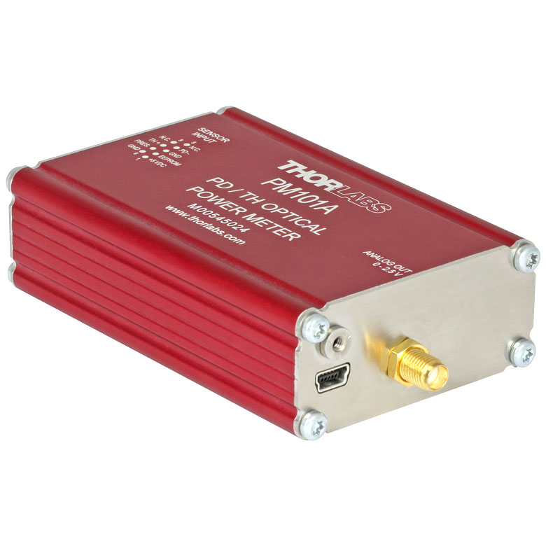 |  | 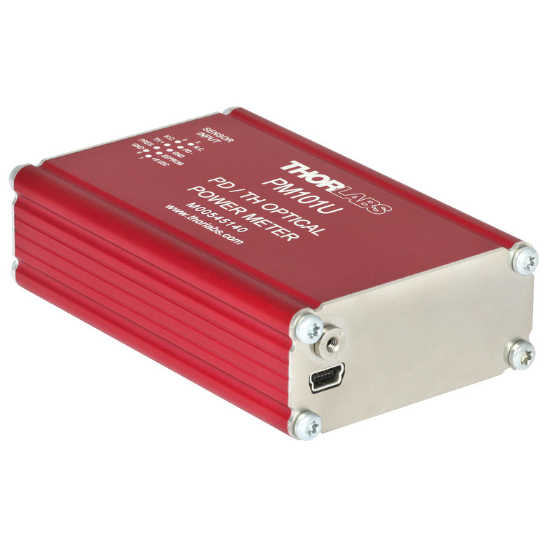 | 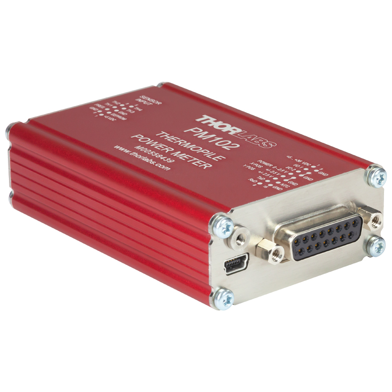 | 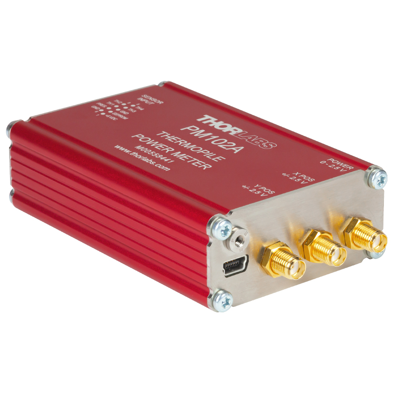 | 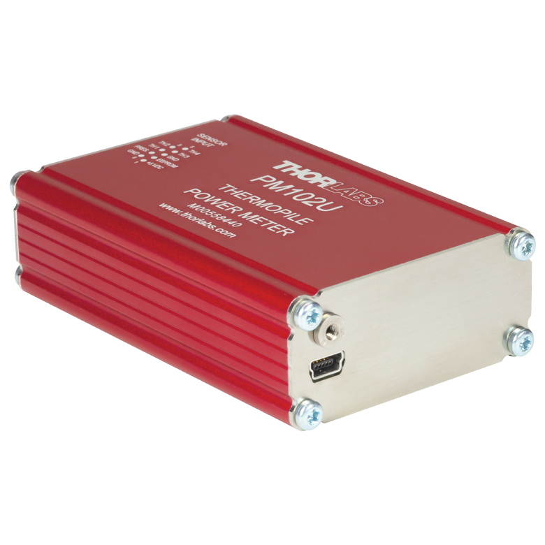 |
| Sensor Compatibility | |||||||
| Photodiode Sensors | | | | | - | - | - |
| Thermal Power Sensors | | | | ||||
| Thermal Position & Power Sensors | - | - | - | - | |||
| Pyroelectric Sensors | - | - | - | - | - | - | - |
| Connectors | |||||||
| C-Series Sensor DE-9 Connector | | | | | | | |
| USB Connector | Lockable | Lockable | Lockable | Lockable | Lockable | Lockable | Lockable |
| Serial DE-9 Connector | - | - | | - | - | - | - |
| SMA Output Connector(s) | - | 1 Analog Power Output | - | - | - | 3 Ports: Power, X Position, and Y Position | - |
| DA-15 Universal Connector with 2 Auxiliary I/O Ports | | - | - | - | - | - | |
| Ethernet (RJ45) Connector | - | - | - | - | - | - | - |
| Phoenix DMC 0,5/7 Connector | - | - | - | - | - | - | - |
| Item # | PM103 | PM103A | PM103E | PM103U | PM100USB |
|---|---|---|---|---|---|
| Photo (Click to Enlarge) | 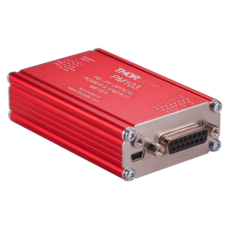 | 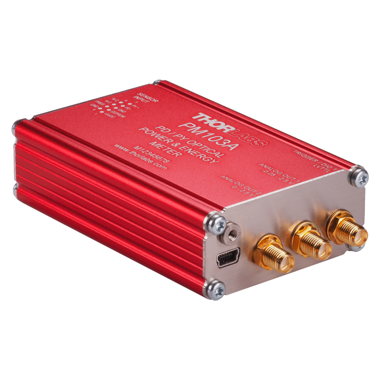 | 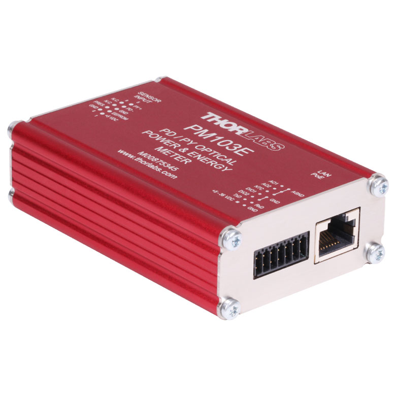 |  | 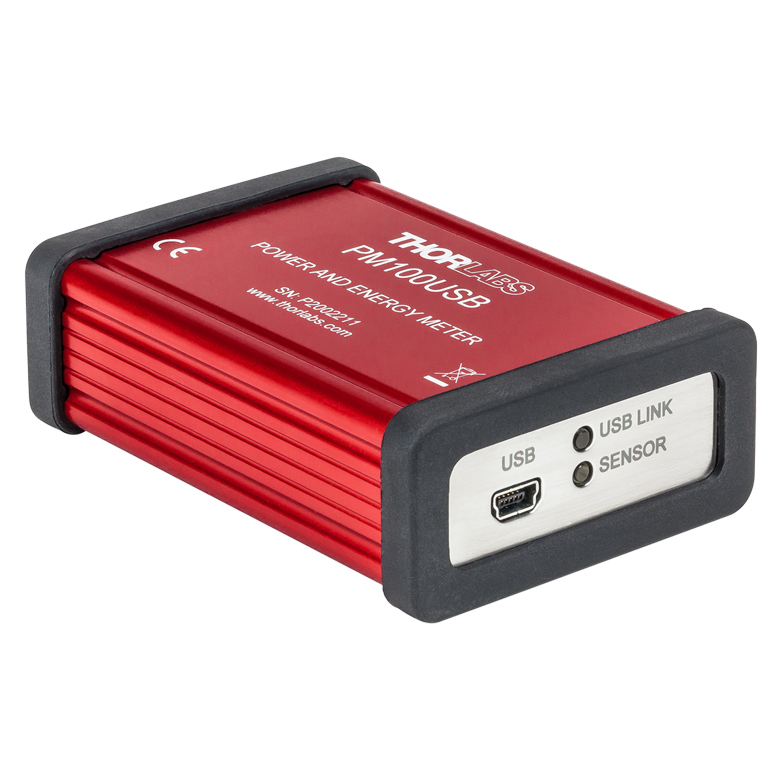 |
| Sensor Compatibility | |||||
| Photodiode Sensors | | | | | |
| Thermal Power Sensors | - | - | - | - | |
| Thermal Position & Power Sensors | - | - | - | - | - |
| Pyroelectric Sensors | | a | |||
| Connectors | |||||
| C-Series Sensor DE-9 Connector | | | | | |
| USB Connector | Lockable | Lockable | - | Lockable | Not Lockable |
| Serial DE-9 Connector | - | - | - | - | - |
| SMA Output Connector(s) | - | 3 Ports: AO1, AO2, and Digital I/O (Configurable as External Trigger Input) | - | - | - |
| DA-15 Universal Connector with 2 Auxiliary I/O Ports | GPIO Ports Also Configurable as Trigger Input (Pin 2) or for Pass/Fail Analysis (Pin 3) | - | - | - | - |
| Ethernet (RJ45) Connector | - | - | - | - | |
| Phoenix DMC 0,5/7 Connector | - | - | - | - | |
アナログ出力
PM101にはアナログ出力ポートが2つあり、DA-15コネクタ内のピン(AO1、AO2)に割り当てられています。AO1からの信号の電圧値は選択された測定レンジに比例しますが、DAC経由で送られている信号ではなく、波長補正やゼロ補正はされていません。AO2からの信号はDACで制御されており、測定レンジに依存しない電圧が出力されます。この信号はOPMソフトウェアまたはSCPI/ドライバコマンドで設定された値に比例します。PM101Aのアナログ出力はPM101のAO2出力と同じ機能ですが、出力はSMAコネクタ経由となります。詳細についてはマニュアルをご覧ください。
PM102では、POWER、X POS、Y POS用として、DA-15コネクタ内のピンにアナログ信号出力ポートが3つ割り当てられています。POWERからの信号はDACで制御されており、測定レンジに依存しない電圧が出力されます。この信号はOPMソフトウェアまたはSCPI/ドライバコマンドでユーザが設定した値に比例します。X POSとY POSからの信号は、センサ上のビームの相対位置とユーザが設定した値に比例した電圧値です。PM102Aのアナログ出力はPM102シリーズのアナログ出力と同じ機能ですが、出力はSMAコネクタ経由となります。詳細についてはマニュアルをご覧ください。
PM103にはアナログ出力ポートが2つあり、DA-15コネクタ内のピン(AO1、AO2)に割り当てられています。AO1からの信号の電圧値は選択された測定レンジに比例しますが、DAC経由で送られている信号ではなく、波長補正やゼロ補正はされていません。AO2からの信号はDACで制御されており、測定レンジに依存しない電圧が出力されます。この信号はOPMソフトウェアまたはSCPI/ドライバコマンドで設定された値に比例します。PM103Aには、SMAコネクタによるアナログ出力ポートが2つあります。それらの機能はそれぞれPM103のAO1とAO2に対応しています。詳細についてはマニュアルをご覧ください。
PM101、PM102、PM103、PM101A、PM102A、PM103Aの場合、アナログ出力だけを必要とする時には、ユニットに電源を供給するだけで単独で使用することができます。
センサーコネクタ(すべてのモデル)
Dタイプメス型
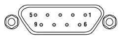
| Sensor Connector Pin Assignments | ||||
|---|---|---|---|---|
| Pin | PM101 Series | PM102 Series | PM103 Series | PM100USB |
| 1 | +5 V (Drive Max 100 mA from this Pin) | +5 V (Drive Max 50 mA from this Pin) | ||
| 2 | DO NOT USEa | |||
| 3 | Analog Ground for PD Anode, Thermal Sensor, and NTC | Analog Ground for Thermal Sensor and NTC | Analog Ground for PD Anode, Pyroelectric Sensor, and NTC | Analog Ground for PD Anode, Thermal, and Pyroelectric Sensor |
| 4 | PD Cathode | Thermal Sensor Input Quadrant 3 | PD Cathode | PD Cathode |
| 5 | N.C. | Thermal Sensor Input Quadrant 4 | Pyroelectric Sensor Input | Pyroelectric Sensor + |
| 6 | Digital Ground for EEPROM and 5 V Output | |||
| 7 | Present: Sensor Recognition, NTC Input. Connect this Pin via a 1 kΩ to 10 kΩ Resistor to Pin 3 (AGND) to Enable a Custom Sensor | |||
| 8 | Thermal Sensor + | Thermal Sensor Input Quadrant 1 | N.C. | Thermal Sensor + |
| 9 | N.C. | Thermal Sensor Input Quadrant 2 | N.C. | N.C. |
USB 2.0ポート(PM103Eを除くすべてのモデル)
USB Mini-B コネクタ
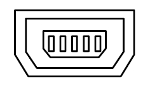
USBケーブル(Mini-B - Type-A)が付属します。
| Item # | PM101 Series | PM102 Series | PM103 Series | PM100USB |
|---|---|---|---|---|
| Remote Interface Type | USB 2.0a | |||
| Connector | Mini-B USB, Lockable | Mini-B USB, Lockable | Mini-B USB, Lockable | Mini-B USB |
| Measurement Speed | Up to 1000/s | Up to 500/s | 1 kS/s + 100 kS/s Bulk Mode | N/A |
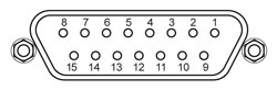
シリアルDA-15コネクタ(PM101、PM102、PM103のみ)
DA-15メス型
| DA-15 Connector Pin Assignments | |||
|---|---|---|---|
| Pin | PM101 | PM102 | PM103 |
| 1 | Pin for Alternative Power Supply with 5 to 36 VDC | ||
| 2 | I/O 1 General Digital Input/Output Port; 3 V Logic (Output), 5 V Tolerant for Input | ||
| 3 | I/O 2 General Digital Input/Output Port; 3 V Logic (Output), 5 V Tolerant for Input | ||
| 4 | Analog Output; -0.25 to +2.5 V per Measurement Range | Software Configurable Analog Output for Beam Power; 0 to 2.5 V | Analog Output; -0.25 to +2.5 V per Measurement Range |
| 5 | Software Configurable Analog Output; 0 to 2.5 V | Software Configurable Analog Output for X-Position; -2.5 to 2.5 V | Software Configurable Analog Output; 0 to 2.5 V |
| 6 | N.C. | Software Configurable Analog Output for Y-Position; -2.5 to 2.5 V | N.C. |
| 7 | RS232 to PC Terminal RxD | ||
| 8 | RS232 to PC Terminal TxD | ||
| 9 | Power Supply Ground | ||
| 10 | Ground | ||
| 11 | Ground | ||
| 12 | Ground | ||
| 13 | Ground | ||
| 14 | NTC Thermistor Input; Measurement Range 0.1 to 100 kΩ | ||
| 15 | RS232 Signal Ground | ||
| Item # | PM101 | PM102 | PM103 |
|---|---|---|---|
| RS232 Communication | |||
| DA-15 Pins | 7 and 8 | ||
| Baud Rate | 9600 - 230400 Bit/s Default: 115200 Bit/s | ||
| Settings | N1S | ||
| Measurement Speed | Up to 200/s | Up to 200/s | 200/s + 100 kS/s Bulk Mode |
| Analog Output, Configurable | |||
| DA-15 Pin(s) | 5 | 4 (Power), 5 (X-Position), and 6 (Y-Position) | 5 |
| Signal | Gain Signal Configurable | Power (Configurable in V/W), X-Position & Y-Position (Configurable in V/µm) | Gain Signal Configurable |
| Voltage Range | 0 to 2.5 V | Power: 0 to 2.5 V; Positions: -2.5 V to +2.5 V | 0 to 2.5 V |
| Accuracy | ±1% | ||
| Bandwidth | 1 kHz | ||
| Analog Output, Not Corrected | |||
| DA-15 Pin | 4 | N/A | 4 |
| Signal | Amplified Input Signal - Not Corrected | N/A | Amplified Input Signal - Not Corrected |
| Voltage Range | 0 to 2.5 V | N/A | -0.25 to 2.5 V |
| Accuracy | ±3% | N/A | ±3% |
| Bandwidth | Up to 100 kHz, Dependent on Sensor and Settings | N/A | Up to 1 MHz, Dependent on Sensor and Settings |
| Auxiliary Temperature Control | |||
| DA-15 Pin | 14 | ||
| Supported Tempearature Sensor | Thermistor NTC 0.1 - 100 kΩ, B-Value: 1000 - 9999 K | ||
| Temperature Measurement Range | -40 °C to +200 °C (NTC Dependent) | ||
| Digital Control Pins I/O | |||
| DA-15 Pins | 2 and 3 | ||
| Signal | 2 x GPIO | 2 x GPIO | 2 x GPIO or Configurable as Trigger Input/Output, Pass/Fail Analysis |
| Power Management | |||
| DA-15 Pins | 1 and 9 | ||
| DC Input | +5 VDC to +36 VDC | ||
シリアルDE-9コネクタ(PM101Rのみ)
DE-9メス型
| Item # | PM101R |
|---|---|
| RS232 Communication | |
| DE-9 Pins | 2 and 3 |
| Baud Rate | 9600 - 230400 Bit/s Default: 115200 Bit/s |
| Settings | N1S |
| Measurement Speed | Up to 200/s |
| DE-9 Connector Pin Assignments | |
|---|---|
| Pin | PM101R |
| 1 | N.C. |
| 2 | RS232 to PC Terminal RxD |
| 3 | RS232 to PC Terminal TxD |
| 4 | N.C. |
| 5 | Ground |
| 6 | N.C. |
| 7 | N.C. |
| 8 | N.C. |
| 9 | N.C. |
SMAコネクタ(PM101A、PM102A、PM103Aのみ)
| Item # | PM101A | PM102A | PM103A |
|---|---|---|---|
| SMA Connector(s) (Click to Enlarge) | 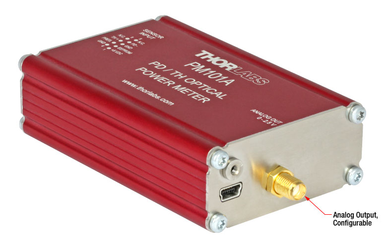 | 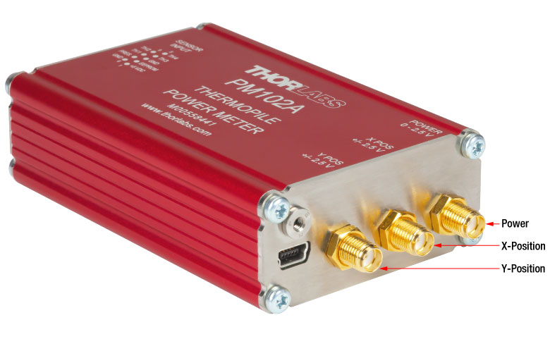 |  |
| Analog Output, Configurable | |||
| SMA Connector(s) | Analog Output | Power, X-Position, and Y-Position | AO2 |
| Signal | Gain Signal Configurable | Power (Configurable in V/W), X-Position & Y-Position (Configurable in V/μm) | Gain Signal Configurable |
| Voltage Range | 0 to 2.5 V | Power: 0 to 2.5 V; Positions: -2.5 V to +2.5 V | 0 to 2.5 V |
| Accuracy | ±1% | ||
| Bandwidth | 1 kHz | ||
| Analog Output, Not Corrected | |||
| SMA Connector | N/A | N/A | AO1 |
| Signal | N/A | N/A | Amplified Input Signal - Not Corrected |
| Voltage Range | N/A | N/A | -0.25 V to 2.5 V |
| Accuracy | N/A | N/A | ±3% |
| Digital Control I/O | |||
| SMA Connector | N/A | N/A | Digital I/O |
| Signal | N/A | N/A | GPIO or Configurable as Trigger Input/Output |
Phoenix DMC 0,5/7およびイーサネットRJ45コネクタ(PM103Eのみ)
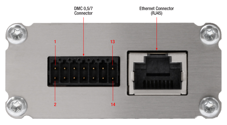
Click to Enlarge
PM103Eのインターフェイスコネクタ
| Phoenix DMC 0,5/7 Connector Pin Assignments | |
|---|---|
| Pin | PM103E |
| 1 | Pin for Alternative Power Supply with 5 to 36 VDC |
| 2 | Power Supply Groud/ Digital Ground |
| 3 | RS232; Connect to PC Terminal RxD (PC DE-9 Pin 2) |
| 4 | RS232; Connect to PC Terminal TxD (PC DE-9 Pin 3) |
| 5 | I/O 2 General Digital Input/Output Port; 3 V Logic (Output), 5 V Tolerant for Input |
| 6 | Digital Ground |
| 7 | I/O 1 General Digital Input/Output Port; 3 V Logic (Output), 5 V Tolerant for Input |
| 8 | Digital Ground |
| 9 | NTC Thermistor Input; Measurement Range 0.1 kΩ to 100 kΩ |
| 10 | Analog Ground |
| 11 | Software Configurable Analog Output; 0 V to 2.5 V |
| 12 | Analog Ground |
| 13 | Analog Output; -0.25 V to +2.5 V per Measurement Range |
| 14 | Analog Ground |
| Item # | PM103E |
|---|---|
| RS232 Communication | |
| DMC 0,5/7 Pins | 3 and 4 |
| Baud Rate | 9600 - 256000 Bit/s Default: 115200 Bit/s |
| Settings | N1S |
| Measurement Speed | 200 S/s + 100 kS/s Bulk Mode |
| Item # | PM103E |
|---|---|
| Remote Interface Type | Ethernet |
| Connector | RJ45 |
| Measurement Speed | 1 kS/s + 100 kS/s Bulk Mode |
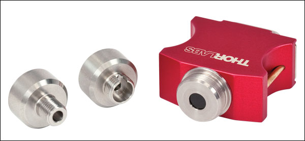
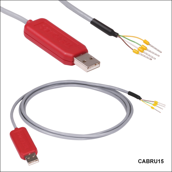
RS232シリアルコネクタ、USB-シリアルフライングリードアダプターケーブルCABRU15の接続用
USB(Type A)-シリアルフライングリード
アダプターケーブル CABRU15

| Cable Lead Assigments | |
|---|---|
| Lead Color | Function |
| WHITE | +5 V |
| BROWN | GND |
| GREEN | RxD |
| YELLOW | TxD |
| DA-15 Pin to Lead Assignments | DE-9 Pin to Lead Assignments | Phoenix DMC 0,5/7 Pin to Lead Assignments | |||
|---|---|---|---|---|---|
 |  |  | |||
| Pin | PM101, PM102, PM103 | Pin | PM101R | Pin | PM103E |
| 1 | +5 V (WHITE) | 2 | TxD (YELLOW) | 1 | +5 V (WHITE) |
| 7 | TxD (YELLOW) | 3 | RxD (GREEN) | 2 | GND (BROWN) |
| 8 | RxD (GREEN) | 5 | GND (BROWN) | 3 | TxD (YELLOW) |
| 9 | GND (BROWN) | 1, 4, 6-9 | N.C. | 4 | RxD (GREEN) |
| 2-6,10-15 | N.C. | 5-14 | N.C. | ||
標準フォトダイオードセンサ取付けオプション
当社の標準フォトダイオードセンサはコンパクトな設計で、既存の光学システムへ簡単に組み込むことができます。ポスト、 ケージ、レンズチューブのオプションをはじめとする当社の標準的な光学システムへのマウントが可能です。このページには、数種類の組み込み例が掲載されて います。
標準フォトダイオードセンサは、S120-xxシリーズのファイバーアダプタ全製品に対応します。FC/PC およびSMA アダプタは、右に掲載されています。 FC/APC、SC、LC、ST接続用のアダプタもご用意しています。
フリップ式マウントにより、定常の光学系のパワー測定を簡単に行うことができます。パワー測定用に、センサをレーザの光路に配置して、システムの通常操作の間は押し下げておくことができます。
右の写真は直角フリップマウントFM90(/M)です。当社では関節式ポストマウントTRB1/Mもご用意しています。固定可能な関節式マウントにより、センサーヘッドを自由に配置できます。

標準フォトダイオードセンサの前面は、SM1ネジで組み込むことができます。SM1ネジにより、25.4 mm(1インチ)レンズチューブシステムや簡単脱着式マウントへ簡単に取り付けることが可能です。
右の写真は、脱着式ポストマウントKB1P(/M)と30mmケージ用簡単脱着式ケージマウントQRC1Aです。どちらのマウントも、SM1ネジにより、センサーヘッドを組み込めます。
注:S12xCシリーズセンサは厚みがあるため、簡単脱着式マウントQRC1AおよびCP44F(下の写真)をケージシステムから完全に取り外すには、ケージシステムの開いた端まで後退させる必要があります。右の写真のようにケージロッドを3本しか使用していない場合、マウントはケージシステムから簡単に取り外し可能です。
当社では、簡単脱着式マウント付き30 mmケージプレートCP44Fもご用意しています。このマウントは磁石によって結合するので、簡単に繰り返し取り付けることができます。
注:QRC1Aと同様に、CP44Fは閉じた状態のケージシステムから取り外すことはできません。
薄型フォトダイオードセンサ取付けオプション
当社の薄型フォトダイオードセンサは、30 mmケージシステムや光学素子が密に配置された自由空間システムをはじめとするスペースの限られた光学装置にもお使いいただける設計となっています。
右の写真は、30 mmケージシステムに挿入されたセンサS130Cです。この使用例により、センサをケージへ簡単に組み込むことができます。パワー測定に必要な最低限のスペースしか必要としないことがわかります。
薄型フォトダイオードセンサは関節式マウントTRB1/Mの上にも取り付けることができます。このマウントによって、センサをスペースのない光学装置にも繰り返し挿入することが可能です。測定後、センサを回転させることにより光路から外し、通常操作が可能になります。
小型・薄型フォトダイオードセンサ取付オプション
当社の小型の薄型フォトダイオードセンサは、16 mmケージシステムやスロット付きØ12 mm~Ø12.7 mm(Ø1/2インチ)レンズチューブ、そして光学素子が密に配置された自由空間システムをはじめとするスペースの限られた光学装置にお使いいただける設計となっています。
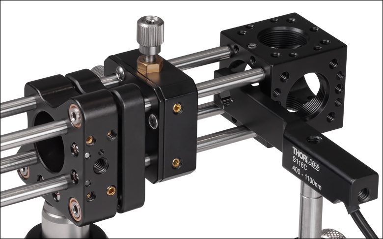
右は16 mmケージシステムに取り付けられたセンサS116Cです。この使用例により、センサをケージへ簡単に組み込むことができます。パワー測定に最低限のスペースしか必要としないことがわかります。
小型の薄型フォトダイオードセンサには、ポスト取付用のM4タップ穴が2つ付いています。右の写真のようにセンサを水平方向に取り付けることができます。もう1つのタップ穴を用いるとセンサを垂直方向に取付可能です。センサは関節式マウントTRB1/Mの上にも取り付けることができます。このマウントによって、センサをスペースのない光学装置にも繰り返し挿入することが可能です。測定後、センサを回転させることにより光路から外し、通常操作が可能になります。
顕微鏡用スライドフォトダイオードセンサ取付オプション
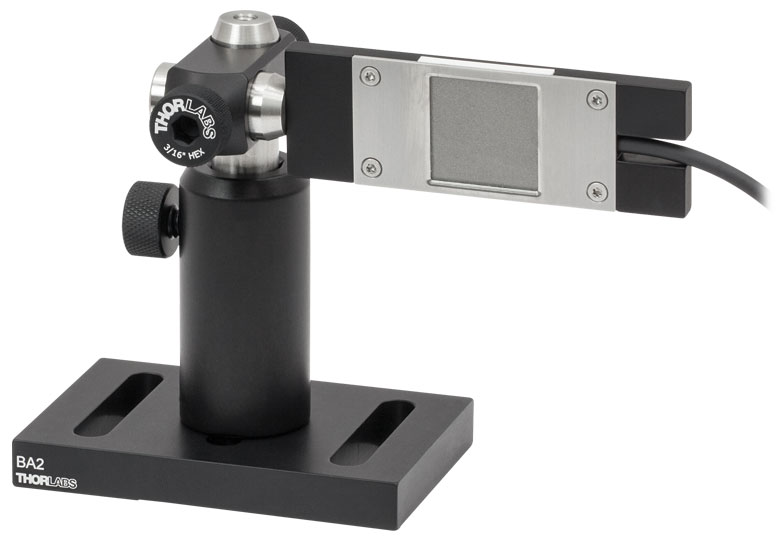
ポストに取り付けたS170C
S170Cは、筐体の側面にあるM4タップ穴を使用してポストに取り付けることができます。
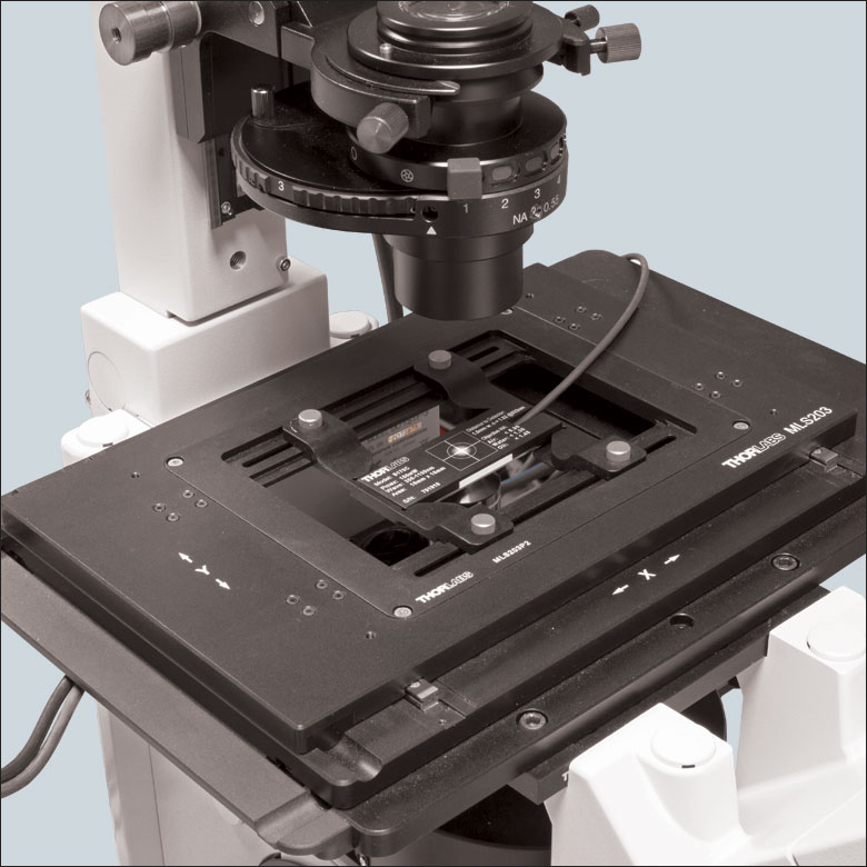
顕微鏡用スライドパワーセンサS170Cは、顕微鏡用スライドホルダに直接取り付けられるよう設計されています。76.0 mm x 25.2 mm x 5.0 mmのセンサーヘッドは、標準の顕微鏡用スライドと同じ設置サイズで、多くの標準的な正立および倒立顕微鏡にお使いいただけます。右の写真ではパワーセンサを裏返して使用しており、筐体の刻印付きの裏面がアライメントに使用できるようになっています。
こちらのパワーセンサにはポスト取り付け用のM4タップ穴も1つ付いています。右の写真ではセンサーヘッドを水平方向に取り付けるため、2本のØ1/2インチ(Ø12.7 mm)ポストにRA90(/M)を使用しています。
積分球フォトダイオードセンサ取付けオプション

当社の積分球フォトダイオードセンサは、発散ビーム、不均一のビーム、軸から外れたビーム向けの低損失キャビティを備えています。積分球はファイバ終端でのビームが発散する光ファイバ関連の用途に適しています。
右の写真はファイバーアダプタS120-FCを付けた積分球フォトダイオードS140Cと、ファイバ素線アダプタS140-BFAを付けたS140Cです。ファイバ素線アダプタには、取り付けクランプと周辺光からの干渉を少なくする遮光体が付いています。
小型ファイバーフォトダイオードセンサ取付けオプション
当社の小型ファイバーフォトダイオードは、ポータブル式ファイバ結合用のパワーメータとして適しています。S15xCセンサは様々なファイバ接続に対応します。 PM20-xx アダプタを使って、センサをFC、APC、SMA、ST、SC、LCコネクタに接続することができます。右の写真はFC&SMAコネクターアダプタをつけたS150Cセンサです。
1番右の写真は、センサS150Cが付いたPM100Dのコンソールです。ここではセンサがFC接続でファイバにつながっています。このセットアップは持ち運びが可能であるため、実験や現場でのご使用に適しています。
焦電エネルギーセンサ取付けオプション

当社の焦電エネルギーセンサは、パルス光源の測定に適していて、光源のエネルギーを直接読み取ることができます。センサは、エキシマ、YAGその他ハイパワーレーザの高エネルギーパルス用に設計されています。
各センサには、Ø12 mm~Ø12.7 mm(Ø1/2インチ)ポストに取付けるための絶縁アダプタが付属しています。また、右の写真のように当社の30 mmケージシステムへの取り付けも可能です。
対応するパワーメータ
- コンソール
- アナログパワー&エネルギーメーターコンソールPM100A
- デジタルパワー&エネルギーメーターコンソールPM100D
- 静電容量タッチパネル式パワー&エネルギーメーターコンソールPM400
- 2チャンネルベンチトップ型光パワー&エネルギーメーターコンソール(バージョン4.0以降)PM5020
- パワーメータ
- Bluetooth®方式ワイヤレスハンドヘルド型パワーメータPM160、PM160T、PM160T-HP
- 小型USBパワーメータPM16シリーズ
- インターフェイス
- PM101シリーズパワーメーターインターフェイス、外部読み出しタイプ(バージョン2.0以降)
- PM102シリーズパワーメーターインターフェイス、外部読み出しタイプ(バージョン2.1以降)
- PM103シリーズパワーメーターインターフェイス、外部読み出しタイプ(バージョン3.0以降)
- USB接続デジタルパワー&エネルギーメーターPM100USB
Optical Power Monitor
このGUIソフトウェアOptical Power Monitorには、パワーの測定、最大8台までのパワーメータの読み取り、およびワイヤレスでのリモート操作といった機能があります。
特定のソフトウェア機能の詳細については、こちらからダウンロードいただけるユーザーマニュアルをご覧ください。
旧世代のPower Meter Softwareについてはこちらのソフトウェアページをご覧ください。
PM101シリーズパワーメータはバージョン2.0以降のみに対応します。PM102シリーズパワーメータはバージョン2.1以降のみに対応します。PM103シリーズパワー&エネルギーメータはバージョン3.0以降のみに対応します。コンソールPM5020はバージョン4.0以降にのみ対応します。
タッチパネル型、ハンドヘルド型、およびUSB接続型光パワーメータ用のGUIソフトウェアOptical Power Monitor
特長
- 最大8台までのパワーメータを同時操作
- リアルタイムでの測定値の記録と解析
- 直感的なアナログ表示とグラフモード
- 設定可能な長時間のデータロギング機能
- サーマル位置&パワーセンサによる位置測定もサポート
- USBおよびBluetooth®接続に対応
Optical Power MonitorのGUIを用いると、USB、RS232またはBluetooth®ワイヤレスa接続により最大8台までのパワーメータのシームレスな制御が可能です。パワーメータ用の最新のソフトウェア、ファームウェア、ドライバ、およびユティリティはこちらからダウンロードできます。
このGUIパッケージには、多チャンネルのデータ測定と解析機能が組み込まれています。インターフェイスは使いやすさを考慮した設計になっています。表示色を最小限にし、輝度も低く抑えているため、レーザ用保護メガネを着用しながらの暗い実験室での使用に適しています。測定データはアナログ針、デジタル数値、線グラフ、あるいは棒グラフでリアルタイムに表示できます。連続したログデータや短時間での測定結果は、後でデータの閲覧や解析を行うために記録することできます。組み込まれている統計モードでは測定データの解析を行い、予め設定された測定周期で新しい測定値を反映させ、連続的に更新を行います。当社のサーマル位置&パワーセンサを用いたビーム位置測定にも対応します。
このソフトウェアパッケージOptical Power MonitorでGUIをインストールすると、すぐにタッチパネル型、ハンドヘルド型、またはUSB接続型のパワーメータの制御にご使用いただけます。対応するパワーメータのファームウェアの更新も可能です。当社のパワー&エネルギーメーターコンソールに使用できる、LabVIEW、Visual C++、Visual C#を用いたプログラム例やドライバが、ソフトウェアと一緒にインストールされます。詳細についてはマニュアルをご覧ください。
なお、このOptical Power Monitor Softwareは、Power Meter Utilities Softwareとは異なるドライバを使用しているのでご注意ください。当社では最新のドライバTLPM.dllのご使用をお勧めします。従来のPower Meter Softwareや以前のドライバPM100D.dllを使用したカスタムソフトウェアを使用したい方のために、2つのバージョンのドライバを簡単に切り替えられるプログラムPower Meter Driver Switcherが付属しています。
a. パワーメータPM160、PM160TおよびPM160T-HPにBluetooth®機能が付いています。
Click to Enlarge
パワー測定モード:最大8台までのパワーメータのセットアップと設定
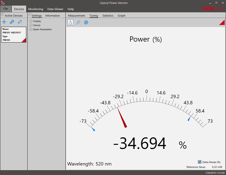
Click to Enlarge
パワーチューニングモード:測定値のアナログ針表示とデジタル数値表示。上図ではデルタモードが有効になっており、測定時間中の変動幅を示しています。
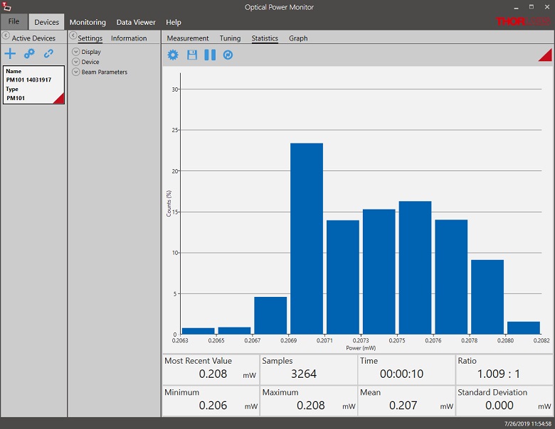
Click to Enlarge
パワー統計モード:予め設定された測定時間における統計量を計算します。上では解析したデータを棒グラフで、計算結果を数値で表示しています。
Click to Enlarge
位置チューニングモード:こちらのチューニングモードはサーマル位置&パワーセンサでのビームアライメントにご使用いただけます。

Click to Enlarge
位置統計モード:統計モードではサーマル位置&パワーセンサの統計情報も表示します。
Click to Enlarge
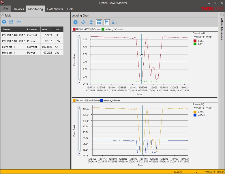
データロギング:長時間測定と最大8台までのパワーメータの同時記録が可能です。データは後処理により.csv形式で保存されますが、測定結果はリアルタイムでグラフ表示されます。

Click to Enlarge
ワイヤレスパワーメータPM160とiPad mini(付属していません)。PM160はApple社のモバイルデバイスを使ってリモート操作が可能です。
こちらでは当社のパワーセンサおよびエネルギーセンサのラインナップをご紹介しています。対応するパワーメーターコンソールとインターフェイスについては右下の表をご覧ください。
下記のパワーセンサおよびエネルギーセンサのラインナップのほかに、当社ではフォトダイオードまたはサーマルセンサのどちらかを内蔵するオールインワン型のワイヤレス機能付きパワーメータや小型USBパワーメータ、およびコンソール、センサーヘッド、ポスト取付け用のアクセサリを含むパワーメーターキットもご用意しております。
当社では4種類のセンサをご用意しております:
- フォトダイオードセンサ: フォトダイオードセンサは感度が波長に依存するので、単色光源もしくは単色に近い光源のパワー測定用に設計されています。このセンサから出力される電流は、入射光パワーと波長によって決まります。この電流はトランスインピーダンスアンプにより、入力電流に比例した電圧を出力します。
- サーマルセンサ: サーモパイルセンサは、広い波長範囲で比較的平坦な応答特性を持つ材料から作られているので、LEDやSLDなどの広帯域光源のパワー測定に適しています。このセンサは、入射光パワーに比例した電圧を出力します。
- サーマル位置&パワーセンサ: これらのセンサでは4つのサーモパイルセンサが正方形の4象限に配置されています。ユニットは各象限からの出力電圧を比較してビームの位置を算出します。
- 焦電エネルギーセンサ: 焦電センサは焦電効果を通じて出力電圧を発生しパルス光源の測定に適しています(ディテクタの時定数によって繰返し周波数は制限されます)。このセンサは、入力パルスエネルギに比例したピーク電圧を出力します。
| Console Compatibility | ||||||||
|---|---|---|---|---|---|---|---|---|
| Console Item # | PM100A | PM100D | PM400 | PM5020 | PM101 Series | PM102 Series | PM103 Series | PM100USB |
| Photodiode Power | | | | | | - | | |
| Thermal Power | | | | | | | - | |
| Thermal Position | - | - | | | - | | - | - |
| Pyroelectric Energy | - | a | a | | - | - | | a |
パワー&エネルギーセンサのセレクションガイド
当社のパワー&エネルギーセンサの仕様を比較する際には、2種類の選択をします。下の表(展開します)では、当社のセンサを種類別に分類して(フォトダイオード、サーマル、焦電)、主な仕様を記載しています。
またその下のセレクションガイドのグラフでは、当社のフォトダイオードならびにサーマルパワーセンサの全ラインナップを波長範囲(左)そしてパワー範囲 (右)で比較できるようになっています。枠内には型番とセンサの仕様の範囲が記載されています。グラフにより、特定の波長範囲またはパワー範囲に適したセンサーヘッドが特定しやすくなっております。
| Photodiode Power Sensors |
|---|


| Thermal Power Sensors |
|---|


| Thermal Position & Power Sensors |
|---|

| Pyroelectric Energy Sensors |
|---|


センサのラインナップ
(波長範囲)
センサのラインナップ
(パワー範囲)
当社では、幅広いパワーメータ&エネルギーメータ用コンソールやパワーセンサ・エネルギーセンサを操作するためのインターフェイスを取り揃えています。 主な仕様は下記でご覧いただけるので、お客様の用途に適したモデルをお選びいただけます。 下記のほかに、センサ内蔵のワイヤレスパワーメータや小型USBパワーメータもご用意しております。
当社のパワーメータ等用のコンソールやインターフェイスは、Cシリーズのセンサとお使いいただく場合は接続したセンサの種類を自動的に認識し、電流値とそれに応じた電圧値を測定します。 Cシリーズのセンサは、コネクタ内に感度特性の校正データが保存されています。 コンソールは、入射波長に対応する感度の値を読み出し、パワーもしくはエネルギの測定値を計算します。
- フォトダイオードセンサは、入射光の光パワーと波長によって決まる電流を流します。 この電流は、トランスインピーダンスアンプに送られ、このアンプから入力電流に比例した電圧が出力されます。 フォトダイオードの感度は波長に依存するため、正確なパワーの測定値を得るためには、コンソールに正しい波長を入力する必要があります。 コンソールは、接続されたセンサから、入力された波長における感度を読み取り、測定した光電流から光パワーを計算します。
- サーマルセンサは、入射された光パワーに比例した電圧を送ります。 測定されたセンサの出力電圧とその感度特性に基づいて、コンソールは入射した光パワーを計算します。
- エネルギーセンサは焦電効果に基づいています。 したがって、エネルギーセンサは、パルスエネルギに比例したピーク電圧を送ります。 エネルギーセンサが認識されると、コンソールはピーク電圧ディテクタを活用し、センサの感度特性からパルスエネルギが計算されます。
コンソールやインターフェイスはセンサが出力する電流や電圧を表示する機能も備えています。 または、測定された電流や電圧をアナログ出力で得ることもできます。
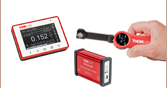
コンソール
| Item # | PM100A | PM100D | PM400 | PM5020 |
|---|---|---|---|---|
| (Click Photo to Enlarge) | 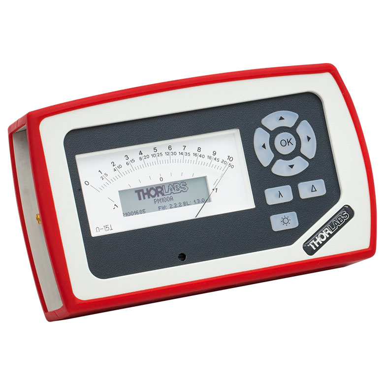 | 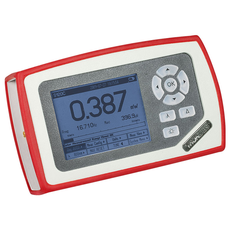 | 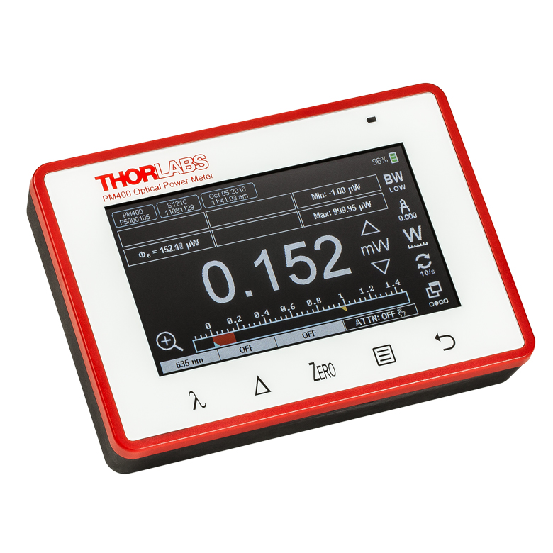 | 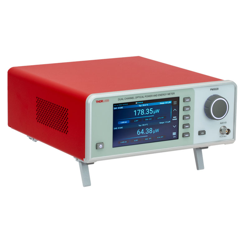 |
| Key Features | Analog Power Measurements | Digital Power and Energy Measurements | Digital Power and Energy Measurements, Touchscreen Control | Dual Channel |
| Compatible Sensors | Photodiode and Thermal Power | Photodiode Power, Thermal Power, and Pyroelectric Energya | Photodiode Power, Thermal Power, Thermal Power and Position, and Pyroelectric Energya | Photodiode Power, Thermal Power, Thermal Power and Position, and Pyroelectric Energy |
| Housing Dimensions (H x W x D) | 7.24" x 4.29" x 1.61" (184 mm x 109 mm x 41 mm) | 7.09" x 4.13" x 1.50" (180 mm x 105 mm x 38 mm) | 5.35" x 3.78" x 1.16" (136.0 mm x 96.0 mm x 29.5 mm) | 9.97" x 4.35" x 11.56" (253.2 mm x 110.6 mm x 293.6 mm) |
| Channels | 1 | 2 | ||
| External Temperature Sensor Input (Sensor not Included) | - | - | Readout and Record Temperature Over Time | Readout and Record Temperature Over Time |
| External Humidity Sensor Input (Sensor not Included) | - | - | Readout and Record Humidity Over Time | Readout and Record Humidity Over Time |
| Input/Output Ports | - | 4 GPIO, Programmable | 4 Configurable Digital I/O Channels | |
| Shutter Control | - | - | - | Support for SH05R(/M) or SH1(/M) Optical Shutter with Interlock Input |
| Fan Control | - | - | - | |
| Source Spectral Correction | - | - | ||
| Attenuation Correction | - | - | ||
| External Trigger Input | - | - | - | |
| Display | ||||
| Type | Mechanical Needle and LCD Display with Digital Readout | 320 x 240 Pixel Backlit Graphical LCD Display | Protected Capacitive Touchscreen with Color Display | |
| Dimensions | Digital: 1.9" x 0.5" (48.2 mm x 13.2 mm) Analog: 3.54" x 1.65" (90.0 mm x 42.0 mm) | 3.17" x 2.36" (81.4 mm x 61.0 mm) | 3.7" x 2.1" (95 mm x 54 mm) | 4.32" x 2.43" (109.7 mm x 61.6 mm) |
| Refresh Rate | 20 Hz | 10 Hz (Numerical) 25 Hz (Analog Simulation) | 25 Hz | |
| Measurement Viewsb | ||||
| Numerical | ||||
| Mechanical Analog Needle | - | - | - | |
| Simulated Analog Needle | - | |||
| Bar Graph | - | |||
| Trend Graph | - | |||
| Histogram | - | - | - | |
| Statistics | ||||
| Memory | ||||
| Type | - | SD Card | NAND Flash | SD Card |
| Size | - | 2 GB | 4 GB | 8 GB |
| Power | ||||
| Battery | LiPo 3.7 V 1300 mAh | LiPo 3.7 V 2600 mAh | - | |
| External | 5 VDC via USB or Included AC Adapter | 5 VDC via USB | Line Voltage: 100 - 240 V | |


| Posted Comments: | |
Dave Walwark
(posted 2024-01-23 12:36:23.797) This is information for prospective buyers and users of the PM100USB (a note on PM101U at bottom).
The USB-query time for a power measurement alone (averaging=1) is 3.1 ms, +/- 1 ms (a 99% CI), but these durations are NOT normally distributed. Most queries are 3.1 ms by far, but ~4 ms is not uncommon (this may be from USB bus issues rather than a device shortcoming). I found the in-practice query-rate to be ~320 Hz, which is slightly better than the specified 300 Hz. However note that the first query in a group will take ~103 ms (delay from autoranging?).
During averaging (averaging > 1), the sample rate is 3 kHz. In the manual (Version 1.7) on page 26 it says each sample takes 3 ms, but this is wrong. Each averaging sample takes about 0.334 ms.
I performed this testing using the pysweepme PM100USB driver in an IDE. See sweep-me.net for free software and PM100USB driver (also K10CR1 driver) that can be used to synchronize lab equipment for experiments.
As an aside, I found that the PM100USB had better noise performance than the PM101U, when comparison of dark-levels of an S405C sensor were made. PM100USB had much smaller standard deviations in the sensor dark level, by a factor of ~20x! I returned the PM101U and got another PM100USB. hchow
(posted 2024-01-25 04:20:11.0) Dear Mr. Walwark, thank you for your valuable feedback. I will let our developers know about these issues. Bernd Kaifler
(posted 2023-09-15 19:55:23.34) I am developing a driver for the PM100USB for our measurement system application (C code base running on Linux). Is there any documentation listing the SCPI commands understood by the device? dpossin
(posted 2023-09-18 10:35:44.0) Dear Bernd,
Thank you for your feedback. The SCPI commands can be found here: C:\Program Files (x86)\IVI Foundation\VISA\WinNT\TLPM\Manual Bert Pilles
(posted 2023-09-12 13:33:13.64) der schnelle Auslesemodus des PM103 (ausgelesen in LabVIEW) scheint fehlerhaft zu sein:
1. es werden absurde Werte angezeigt (10^-34 o.ä.)
2. die Werte skalieren nicht linear mit der eingestrahlten Leistung
Bei anderen Messmodi (Sequez Messung) treten diese Probleme nicht auf GBoedecker
(posted 2023-09-13 04:36:58.0) Thank you for your feedback! I need more details to discuss your question. I will contact you directly. Hogan Pope
(posted 2023-07-17 13:29:05.2) Hello, I"m using PM100D and TLPM library in C# to build a custom software to read power. Basic functions seem to work well, but I can't find a function to read max power measured or to reset the max power measured. Is there anyway to retrieve this data?
Thanks. GBoedecker
(posted 2023-07-18 04:06:43.0) Thank you very much for you feedback! There is no method in the TLPM library that directly delivers the maximum power. You can write this method in your application, based on the method that measures the power. user
(posted 2023-06-07 00:39:38.33) Will the PM103 in combination with an S121C power meter head allow me to resolve a pulsed laser with a pulse duration of about 1ms and a repetition rate of 300 Hz ? The specs say it has a "readout rate" of 100 kS/s, so does that mean I can use the PM103 to sample my pulsed laser waveform with a timing resolution of 10 microseconds ?
Does the standard Thorlabs software allow to do this or do we need to write our own application in order to achieve such fast sampling (similar to an oscilloscope) ? wskopalik
(posted 2023-06-12 10:41:00.0) Thank you very much for your feedback!
Yes, pulses with 1 ms duration and 300 Hz repetition rate can be resolved by the PM103 and the S121C. The resolution which can be achieved with this combination is 10 µs.
The provided software has a SCOPE mode which can be used to record data with 100kS/s. This mode works similar to an oscilloscope. I will contact you directly to provide further information. Guillaume Gilson
(posted 2023-04-05 09:46:20.44) Hello :) I am using a PM101 readout device to interface and measure a custom thermopile sensor (based on TD15A detector). When connecting this custom sensor to a PM400 readout device (with screen), I don't face any issue. When I use the PM101 with Thorlabs OPM software (Windows 10) and the custom sensor, I have no issue. Now, when I try to interface the sensor with the PM101 on a RaspberryPi, using SCPI commands in Python, it doesn't work properly. More precisely, I can interface the PM101 without issue (using SCPI commands) but the readout power/voltage values are not relevant AND insensitive to the power applied to the sensor... Can you provide a command list to make sure it works in this setup?
For completion, here is the command list I use so far:
self.opm.comm.write("INIT")
sleep(0.1)
self.opm.comm.write("INP:ADAP THER")
print(self.opm.comm.ask("INP:ADAP?"))
self.opm.comm.write("CONF:SCAL:POW")
print(self.opm.comm.ask("CONF?"))
self.opm.comm.write("SENS:POW:RANG:AUTO ON")
print(self.opm.comm.ask("SENS:POW:RANG:AUTO?"))
self.opm.comm.write("SENS:AVER 10")
print(self.opm.comm.ask("SENS:AVER?"))
print(self.opm.comm.ask("SENS:POW:UNIT?"))
self.opm.comm.write("SENS:CORR:POW:THER:RESP 14E-4") #5e-4 print(self.opm.comm.ask("SENS:CORR:POW:THER:RESP?")) #5e-4
print(self.opm.comm.ask("INP:ADAP?"))
sleep(0.5)
for i in range(10):
print(self.opm.ask("MEAS:POW?"))
sleep(0.5) GBoedecker
(posted 2023-04-12 05:16:28.0) Thank you for your feedback! I would recommend to first test the command sequence on the Windows computer. I will contact you directly for further discussion. user
(posted 2023-03-28 12:47:32.987) Dear Thorlabs-Team,
are there Linux drivers for the PM101 available?
Thank you very much,
Jonas fmortaheb
(posted 2023-03-29 06:41:22.0) Thank you very much for contacting Thorlabs. I will contact you directly to provide you with further information. Chance Hanusek
(posted 2022-12-15 12:34:16.153) Not seeing a spec PDF. For most products there is a 4 page summary flyer (e.g. S120C-SpecSheet) but not PM100USB. Only seeing the manual.
Is there a SpecSheet? hchow
(posted 2022-12-16 05:20:28.0) Dear Mr. Hanusek, thank you for your feedback. Yes, you can see the specifications sheet for the PM100USB by clicking on the "Specs" tab on this webpage. Alternatively, you can also click and download the Manual for the PM100USB, and the technical specifications for this device is found on page 32. Thank you. Yun Jang
(posted 2022-07-23 16:17:22.83) Hello, I"m using PM100USB and TLPM library to build a custom software to read power. Basic functions seem to work good, but I can't find a function to read range values.
When you turn off auto-range, you can select one of the range values (maximum value of each range). Can you let me know how to retrieve those range values? It seems TLPM.h defines these ranges values for current and energy, but not power. Thanks. wskopalik
(posted 2022-07-26 05:48:59.0) Thank you very much for your feedback!
There is a function “TLPM_setPowerRange” which can be used to select the power range. As an input, you can enter the expected power of your light source and the power meter will switch to the range just above this power. The minimum and maximum power range can also be retrieved by using the function “TLPM_getPowerRange”.
I will contact you directly to provide further assistance. Samuel Eardley
(posted 2022-05-06 14:12:10.173) Hi
I am using the PM103U with a ES111C Pyroelectric Energy Sensor.
Whenever I change the measurement range the measured energy changes. For example when the range is set to 270uJ it measures a pulse as 177uJ, then if I change the range to 550uJ the measured energy jumps up to 213uJ.
Is this a known issue or do I have a faulty meter?
Which measurement should I trust? hkarpenko
(posted 2022-05-10 10:14:23.0) Dear Samuel,
thank you very much for your feedback.
The behaviour you are observing, is normal and is due to the measurement principal of the pyroelectric sensor.
I will contact you directly to discuss this further with you. user
(posted 2020-10-09 03:16:34.947) Hello, can you please provide the information how to use this power meter with Raspberry pi? wskopalik
(posted 2020-10-13 05:37:28.0) Thank you very much for your inquiry.
A Raspberry Pi usually works with a Linux-based operating system. We can provide drivers for Ubuntu for the optical power meters which might be compatible with the Raspberry Pi operating system as well. Alternatively, you can e.g. use PM101 or PM101R which have an RS232 interface which is available on the Raspberry Pi as well. So you could communicate with the power meter directly on this interface and would not need any additional drivers.
I have contacted you directly to discuss these options in more detail. X Sun
(posted 2020-07-08 12:33:29.57) I have downloaded the the power meter utility 2.2.
run the software my PM100USB doesn't appear in the device list window, rescan or unplug/plug didn't work. Though the PM100USB showed in windows Device manger with no error. MKiess
(posted 2020-07-09 05:27:04.0) This is an response from Michael of Thorlabs. Thank you very much for your inquiry. The Thorlabs Optical Power Monitor (OPM) uses the newer power meter driver TLPM.dll instead of the formerly used NI-VISA™-based driver PM100D.dll.
Although both drivers are included in the download, the new TLPM.dll driver is automatically installed with the OPM software. The driver can be changed with the tool, Driver Switcher. So if you are using the OPM software, make sure that the TLPM.dll drivers used. I have contacted you directly to discuss further details. Ekin Kocabas
(posted 2020-06-18 10:55:17.2) This is in response to the question by "Moritz Jung (posted 2020-05-28 09:26:52.493)"
I found the following functions in TLPM drivers useful for sending SCPI commands to the power meter (though I ended up not using this feature much). As MKiess mentioned, a call to TLPM_init is needed to initialize the connection first.
TLPM_writeRaw
TLPM_readRaw MKiess
(posted 2020-06-19 09:23:48.0) This is a response from Michael at Thorlabs. Thank you very much for this feedback and for completing this information. Moritz Jung
(posted 2020-05-28 09:26:52.493) Hello, I have a similar question as asked before in these comments: According to the manual, the new TLPM.dll driver can be used togehter with SCPI commands, "as long as the user establishes an USBTMC protocol". Can you give any details on how this is supposed to be done? Is it possible to use the OPM software without changing the driver?
When I switch to the old PM100D driver, the device can be accessed via NI-VISA. But I would prefer sticking to the up to date drivers.
Thanks for your answer! MKiess
(posted 2020-06-05 05:21:47.0) This is a response from Michael at Thorlabs. Thank you very much for your inquiry. You can use the OPM software with the TLPM drivers as well as communicate with the TLPM drivers via SCPI commands.
When installing the OPM software, the TLPM drivers are installed by default and are used when the software is started.
When communicating via SCPI commands and using the TLPM driver, the device must be initialized with the TLPM functions, i.e. with the function "TLPM_init".
Afterwards the driver functions can be used together with the SCPI commands for communication. Ekin Kocabas
(posted 2019-10-18 18:37:25.303) I use a S154C detector connected to PM101 and I observe the AO1 fast analog output of the power meter via an oscilloscope as I apply a square current pulse to a laser diode. With another detector/power meter combination I can see ~1 microsecond rise-time (detector limited), however, S154C + PM101 combination results in 28 ms (bandwidth high) or 38 ms (bandwith low setting) rise times. This is very different than the 100 KHz bandwidth in the PM101 specs. What is a typical rise-time that I should expect from S154C? Are there other detectors compatible with PM101 which would lead to faster rise times? If there is a special setting that I need to apply to observe KHz level signals could you let me know? Thank you. dpossin
(posted 2019-10-25 06:22:33.0) Dear Ekin,
Thank you for your feedback. As the bandwith of our powermeter are limited to a maximum value of 100kHz, we can not provide a rise time of 1µs. The behaviour you are observing is due to a firmware bug which always kept the bandwith on low status. We corrected this issue with the last firmware update which we will provide on our website ASAP. I reached out to you in order to provide further assistance. Sajjad Haidar
(posted 2019-10-03 11:02:33.577) Hello
I have been using PM101 interface with a thermal sensor.
I was wondering, do you have any Python support files for PM101?
Thanks MKiess
(posted 2019-10-10 06:02:20.0) This is a response from Michael at Thorlabs. Thank you very much for your inquiry. I contacted you directly to send you the necessary information to control the PM101 in Phython. Ekin Kocabas
(posted 2019-08-26 18:20:09.663) I had two questions on PM100USB power meters. [Q1] The latest version of the manual (ver 1.4, date 9 Aug 2019) states in Sec 7.1 that "the user can use the SCPI commands with the new TLPM.dll driver, as long as the user establishes an USBTMC protocol." Can you provide details on establishing a USBTMC connection to PM100USB, what additional piece of software do I need? [Q2] The new PM101x Write Your Own Application manual (Version: 1.0 Date: 12-Aug-2019) provides three tables that summarize status registers in Sec 3.4 for PM101 series power meters. Can you provide a similar set of tables for PM100USB? Thank you. MKiess
(posted 2019-08-29 08:34:23.0) This is a response from Michael at Thorlabs. Thank you very much for your inquiry. For USBTMC a VISA installation is necessary. NI-VISA is the most widely used, but other implementations like TekVISA are also possible.
I contacted you directly to provide further support and to send you the desired status register for the PM100USB. hartwig s
(posted 2019-07-09 08:09:16.16) Be advised when measuring DLP projectors with the PM100-USB: The auto-adjust function for the measurement range in the software specifically cannot handle DLP projectors (running ramp protocols). In general, it is better to manually set the measurement range beforehand. MKiess
(posted 2019-07-12 09:08:08.0) This is a response from Michael at Thorlabs. Thank you very much for the feedback. Depending on the wavelength of the measured light and the sensor used, it is essential to set the wavelength in the Optical Power Monitor software to compensate the measurement result for the wavelength-dependent sensitivity of the sensor.
Therefore, when measuring DLP projectors, it is a good solution to adjust the settings manually. In general, it is recommended to use the default Auto Range ON setting.
Auto Range OFF allows you to set the measurement range manually, which is recommended for measuring pulsed light sources, for example. anish.goel
(posted 2019-03-04 13:19:21.693) Hi, I am interfacing the TLPM in C# but unable to find any documentation regarding the functions (specifically "return values from functions" for example int setwavelength: What will it return. What will it mean)
Where do I find proper documentation for the SDK ? swick
(posted 2019-03-08 03:23:38.0) This is a response from Sebastian at Thorlabs. Thank you for the inquiry.
After installing the software package you can find documentation about the functions at path:
C:\Program Files (x86)\IVI Foundation\VISA\WinNT\TLPM\Manual kocabass
(posted 2019-02-19 16:45:38.96) Hello,
When I use the TLPM library drivers wrapped in python via ctypes, I see that I get different measurement results if I issue a 1 sec wait time between TLPM_setWavelength and TLPM_measPower vs the case when there is no wait time. It seems like the TLPM_setWavelength function call takes some time to finalize but it returns back to the enclosing program before then. I tried to look into various device registers to determine when setWavelength operation ends but could not find the right register location for that. I'd appreciate any comments on how I can make sure that the TLPM_setWavelength calls have done what they are supposed to do, without having to issue wait commands in between wavelength change and measure commands. nreusch
(posted 2019-02-26 06:42:59.0) This is a response from Nicola at Thorlabs. Thank you very much for the inquiry. You could probably add a loop to your program using the TLPM_getWavelength command to check whether set and get wavelength match before the program actually performs a measurement. I will contact you directly for further assistance. ericshaner8d
(posted 2018-12-26 09:24:11.07) The description under 'software' for the PM100USB says 'visual basic' examples are included with the driver. They are not, just C and C# are included. nreusch
(posted 2019-01-03 07:26:25.0) This is a response from Nicola at Thorlabs. Thank you for the note. You are right about the fact that Visual Basic examples are not installed with software and drivers. We will correct the statement on our website. segreto
(posted 2018-11-05 10:01:26.68) I have developed my own driver to read data at high speed from the PM100USB and found that the performance of this device is severely limited by the lack of the SCPI command "DATA:FORMAT {FLOAT, ASCII}" that would allow the user to choose to transfer data directly in binary format, thus saving the time required for the (in most of the cases totally useless) binary to ASCII conversion.
Do you plan to implement this command in the near future? swick
(posted 2018-11-21 03:27:17.0) This is a response from Sebastian at Thorlabs. Thank you for sharing your findings with us. We will look into this.
At the time we do not plan to change the SCPI command set. juozas
(posted 2018-10-24 13:02:44.853) Hello,
We're writing custom software that we need to work on multiple operating systems, including Linux and macOS. Are there still no drivers or other tools that would enable development for those operating systems? If writing our own drivers is the only option, where could we get complete documentation?
Thank you! swick
(posted 2018-11-21 04:20:12.0) This is a response from Sebastian at Thorlabs. Thank you for the inquiry.
For Linux we can provide shared objects but for macOS we do not provide drivers at the moment.
I contacted you directly to get further information about the operating systems you work with. ebull
(posted 2018-08-20 11:08:37.53) We use PM100USB and PM100D frequently for measurements with Thorlabs sensors and for measurements with our own photodiodes - the ability to use a custom sensor is very useful to us. We often do not need the screen of the PM100D, but we generally want the analog output that the PM100USB lacks.
A PM100USB with analog output would be the perfect device for many of our uses.
Elias nreusch
(posted 2018-08-23 05:45:12.0) This is a response from Nicola at Thorlabs. Thank you for your suggestion. We are already working on the realization of such a device. I will contact you directly with further information. stefano.valle
(posted 2018-07-31 15:51:34.8) It would be really useful to have a library for Matlab, or at least a set of command line to be able to control to set the power meter and retrieve the data required, without passing through Labview or C++ swick
(posted 2018-08-08 04:36:30.0) This is a response from Sebastian at Thorlabs. Thank you for the feedback.
After establishing the USB connection SCPI commands could be used for remote control. I contacted you directly to provide a list of these commands. jim.mcginnis
(posted 2018-06-06 07:57:31.237) Sent email to tech support regarding the issues below. jim.mcginnis
(posted 2018-06-05 15:44:28.107) Followup:
Windows version is Windows 10, 1803 Creators Spring Update. Reinstalled all drivers from Thorlabs.
Thanks jim.mcginnis
(posted 2018-06-05 15:37:13.973) We have constructed both 32bit and 64bit applications for reading an optical sensor connected to the PM100USB. The applications work correctly on Windows 7.
Building 64 bit C# application that combines the Kinesis 64 bit motion control libraries with the TLPM 64 bit libraries in a single application. Works as expected on Windows 7
Problem arises when building and running on Windows 10. The TLPM calls to get resources returns more than just the PM100USB devices. Selecting the correct device returned by the get resource call and trying to configure the device results in exception thrown by the TLPM call.
This does not happen on the Windows 7 platform. Only Windows 10.
Is this a known problem for the 64 bit TLPM libraries??
We have no issues with the Kinesis 64 bit libraries on Windows 10 or 7.
Suggestions??? jacyjacythomson
(posted 2017-04-24 16:15:16.97) Hi I am trying to develop a small program in LabVIEW like the PM100D Simple Example.
I need the Commands to send to the instrument.
These are similar to :
SENS:AVER
There should be a Programming Command Manual or a link on your website.
Thank you, Jeff swick
(posted 2017-04-26 04:52:50.0) This is a response from Sebastian at Thorlabs. Thank you for the inquiry.
An overview of SCPI commands for our Power Meter Consoles can be found in the manual at chapter "SCPI Commands".
I will contact you directly for further assistance. asmirnov
(posted 2017-02-02 01:10:38.227) We use a number PM100USB interfaces. If two PM100USB connected simultaneously, some of them (about 15% of all) can hang up. It doesn`t depend on NI-VISA RTE/driver/firmware version, MotherBoard model etc. Is it a fabric or software defect? swick
(posted 2017-02-03 05:41:03.0) This is a response from Sebastian at Thorlabs. Thank you for the feedback.
Using more than one PM100USB simultaneously at one operating system should work without problems.
The Power Meter Consoles are based on SCPI commands, which avoids driver conflicts in the operating system.
A known issue which avoids using multiple devices at the same time could be USB-Hubs, bad quality USB cables and/or a slow PC.
I will contact you directly for assistance and troubleshooting. ddeng
(posted 2017-01-31 19:34:13.383) Could you support this PM100USB under Windows 10? I have one unit. wskopalik
(posted 2017-02-01 03:22:18.0) This is a response from Wolfgang at Thorlabs. Thank you very much for your inquiry.
You can use the software provided on the website to operate the PM100USB. Supported operating systems are Windows® XP (32 bit) SP3 or Windows® Vista, 7, 8.1, or 10 (32 bit, 64 bit).
I will contact you directly to provide further assistance. ester0904bond
(posted 2016-03-28 09:22:41.837) Can this modal do data sampling up to 100kHz?
if can, can we do that in labview?
thank you besembeson
(posted 2016-03-28 09:49:18.0) Response from Bweh at Thorlabs USA: This may not be possible, even with a photodiode sensor though we have a 16 bit AD converter in the PM100USB. Speed loss could come from the queries of commands which always checks the availability/status of the sensor. You could write your own routines which allows for faster sampling rates but the USB 2.0 port will limit this and the PM100USB has no analog output to bypass this. You may consider instead the PM100D, PM100A or the PM200. roger_york
(posted 2016-03-11 19:01:25.26) Is there anyway to interface the PM100USB with a MacBook Air? shallwig
(posted 2016-03-14 11:53:36.0) This is a response from Stefan at Thorlabs. Thank you very much for your inquiry. At the moment we have unfortunately no drivers available to run our power meter software with Apple OS. nherrick
(posted 2015-10-22 16:40:57.477) What do you think are the chances of being able to use the PM100USB with a raspberry pi? tschalk
(posted 2015-10-23 07:11:50.0) This is a response from Wolfgang at Thorlabs. Thank you for your inquiry. A Raspberry Pi usually works with a Linux-based operating system for which we unfortunately can't offer full support. There is however some information about the use of our powermeters in Linux and I will contact you directly about it. johnhobbs
(posted 2015-09-30 13:34:26.513) Please fix your labview drivers for the PM100USB! I just upgraded to Labview 2015 and your labview drivers now hang up. I can send my labview driver if you want for the PM100USB. bottom line you cannot ini the PM100USB read the power and then close the device multiple times without it hanging up. I think your drives are not properly closing the resources for the device.
best,
John Hobbs shallwig
(posted 2015-10-01 09:55:41.0) This is a response from Stefan at Thorlabs. Thank you very much for your inquiry. We checked the drivers with Labview 2015 and could not reproduce this problem. I will contact you directly to troubleshoot this in more detail. bo.jing
(posted 2015-05-26 17:42:20.707) The inner plastic (grey) USB connector on the PCB board inside the device detached itself at the soldering points. Can I send this unit back for repairs? We are quite disappointed at this obvious point of failure. shallwig
(posted 2015-05-27 06:33:02.0) This is a response from Stefan at Thorlabs. Thank you very much for contacting us in this matter. We are really sorry for the inconveniences you had through this. I will contact you directly to handle the repair/exchange as soon as possible. a.andreski
(posted 2015-05-12 17:41:44.017) Is there a way to read out a time-series of datapoints (lets say 1M samples) using your C-series photodioide sensors with a PM100USB but with a specific sampling rate? tschalk
(posted 2015-05-13 07:02:08.0) This is a response from Thomas at Thorlabs. Thank you very much for your feedback. The maximum achievable sampling rate is about 300Hz. The GUI provides a function called fast logging which enables the maximum logging frequency of the unit. If you want to sample a signal in the MHz range you could use one of our amplified photodetectors in combination with a scope. I will contact you directly to discuss your application. catox
(posted 2014-07-23 15:14:35.38) It would be great if you could offer a similar product with Serial via USB interface to remove the requirement for NI-VISA installation. shallwig
(posted 2014-07-23 09:52:01.0) This is a response from Stefan at Thorlabs. Thank you very much for your feedback. At the moment it is not planned to offer the PM100USB in such a configuration. But the PM160 http://www.thorlabs.com/newgrouppage9.cfm?objectgroup_id=7233&pn=PM160#7267 allows you to communicate with your PC without using VISA as it can additionally to USB also transmit data by Bluetooth. I will contact you directly to discuss your application in detail. bagresci
(posted 2014-04-17 17:10:32.223) I found a method to communicate with pm100usb. I and using Agilient USBTMC kernel driver with Scientific linux 6.4. (http://www.home.agilent.com/upload/cmc_upload/All/usbtmc.html?&cc=KR&lc=kor). Below is my shell script :
./usbtmc_ioctl 1 reset
./usbtmc_ioctl 1 clear
echo INIT > /dev/usbtmc1
while((i<100))
do
./usbtmc_ioctl 1 reset
./usbtmc_ioctl 1 clear
echo READ? > /dev/usbtmc1
cat /dev/usbtmc1
((i=i+1))
done
./usbtmc_ioctl 1 reset
./usbtmc_ioctl 1 clear
echo ABOR > /dev/usbtmc1
./usbtmc_ioctl 1 reset
./usbtmc_ioctl 1 clear shallwig
(posted 2014-04-17 08:49:33.0) This is a response from Stefan at Thorlabs. Thank you very much for your feedback and sharing this helpful information with us. I will contact you directly to discuss any open questions you have in this matter. hadmack
(posted 2013-07-08 17:48:23.577) Could you please provide an update on the compatibility of PM100USB with the Linux USBTMC driver? tschalk
(posted 2013-07-10 08:40:00.0) This is a Response from Thomas at Thorlabs. Thank you very much for your inquiry. To control the device with Linux you would need a USBTMC-driver for Linux and the instrument-driver-code for the corresponding SCPI commands to communicate via the USBTMC driver. The low level specifications are the followings: - Universal Serial Bus Test and Measurement Class Specification (USBTMC) Revision 1.0. USB Implementers Forum. April 14, 2003 - and - Universal Serial Bus Test and Measurement Class, Subclass USB488 Specification (USBTMC-USB488) Revision 1.0. April 14, 2003 - and the command structures are - IEEE Std 488.2-1992; IEEE Standard Codes, Formats, Protocols, and Common Commands For Use With IEEE Std 488.1-1987, IEE Standard Digital Interface for Programmable Instrumentation - and the used command format is - Standard Commands For Programmable Instruments (SCPI) -. You can use the source code of our instrument driver which is an open source code under LGPL. This one can be changed so that it is possible to use the Linux - USBTMC communication instead of the NI functions. I will contact you directly for more detailed information. jvigroux
(posted 2012-06-20 09:54:00.0) A response from Julien at Thorlabs: Thank you for your feedback! The communication of the PM100USB is based on the USBTMC protocol. We rely on the VISA engine to create a stable overlayer on the USBTMC but if one does not want to use the VISA engine, it is of course possible to address the USB port directly at a USBTMC level. I will contact you to discuss further the possible approaches for the driver implementation you plan. gnishi
(posted 2012-06-19 20:45:33.0) It would be great to provide the Linux driver or low level USB specification to write the driver. We don't need NI plat form, which consumes huge resources (incl. cost.), to drive this powermeter. jjurado
(posted 2011-04-06 16:35:00.0) Response from Javier at Thorlabs to last poster: Thank you very much for your feedback. I will share your comments with our design engineers for the PM100USB. Please check back with us at techsupport@thorlabs.com if you would like to check on the status of this project. user
(posted 2011-04-06 18:40:07.0) It would be great to have a product like this compatible with Android, and be able to use on a tablet or smartphone. jjurado
(posted 2011-02-14 18:14:00.0) Response from Javier at Thorlabs to huw.major: Thank you for submitting your inquiry. The crashing is most likely due to an older firmware version of the PM100USB power meter. You can upgrade to version 1.3 by installing the Device Firmware Upgrade wizard and following the instructions. You can download the firmware application via the following link:
http://www.thorlabs.com/software_pages/ViewSoftwarePage.cfm?Code=PM100x
I will follow up with you directly. huw.major
(posted 2011-02-14 11:37:25.0) Hi, I have 3 of these products and am trying to use them for prolonged testing purposes, > 1000Hrs constant use. I find them very easy to set up and use, but I have found that they constantly crash. I am using a Labview 2009 program, based on your supplied Labview example code, which seems to work fine most of the time. However, I am getting sporadic crashed of 1 or more power meters which require a power down to fix. The code is running under Windows 7, do you know of any issues with this combination? huw.major
(posted 2011-02-14 11:32:47.0) Hi I have 3 of these products and am trying to use them for prolonged testing purposes, >1000Hrs constant use. I find them very easy to set up and use, but, I have found that they constantly crash. I am using a Labview 2009 program based on your supplied Labview code which seems to work fine most of the time. However, I am getting sporadic crashes of 1 or more power meters which require a power down to fix. The code is running under Windows 7, do you know of any problems with this combination? julien
(posted 2011-01-28 11:41:52.0) a response from Julien at Thorlabs: Thank you for your feedback. Several PM100USBs can be connected to the same hub. We actually provide a small utility software that allows to readout up to 8 PM100USB simultaneously. This utility can be downloaded from the software page of the PM100USB. Concerning the Iphone compatibility, the PM100USB software is entirely NI VISA based, which is as of now unfortunately not compatible with Iphones yet. mobrien
(posted 2011-01-27 12:46:16.0) I was wondering if you have given any thought to making a PM100USB App for the iPhone etc. Our company currently does not provide smartphones or tablets to its employees but you can kind of see where things are heading...
On a related topic, we have one of these, could I connect multiple PM100USBs to a single USB port via a USB hub?
Mike |

 ズーム
ズーム| Power Meter Interface Quick Comparisona | ||||
|---|---|---|---|---|
| Item # | PM101 | PM101A | PM101R | PM101U |
| Photo (Click to Enlarge) | | | | |
| Connectors | Mini USB & DA-15 | Mini USB & SMA | Mini USB & DE-9 | Mini USB |
| Control / Digital Output | USB 2.0, RS232, or UART | USB 2.0 | USB 2.0 or RS232 | USB 2.0 |
| Analog Output | Yes | Yes | No | No |
- 25種類以上のフォトダイオードパワーセンサおよびサーマルパワーセンサに対応
- すべてのモデルはUSB 2.0による操作が可能
- モデル選択の要点
- UARTまたはRS232による操作
- アナログ出力
- USB(すべてのモデル)またはDA-15コネクタ(PM101)による電源供給
- Certificate of Calibration(校正証明書)の添付
PM101シリーズのインターフェイスは当社のすべてのCシリーズのフォトダイオードおよびサーマルパワーセンサに対応します。 当社の標準フォトダイオードセンサ、薄型フォトダイオードセンサ、積分球センサおよびファイバ用センサに対応します。これらのセンサ全体で測定可能な光パワーの範囲は100 pW~20 Wです。一方、当社のサーマルパワーセンサ全体で測定可能な光パワーの範囲は10 µW~200 Wです。そのほか、増幅機能の無い最大光電流が5 mAまでのアノード接地またはカソード接地のフォトダイオード、および最大出力電圧が1 Vまでのサーマル素子もご使用いただけます。すべてのインターフェイスはPCからmini-USBポート経由で操作や電源供給ができますが、さらに一部のインターフェイスはUARTまたはRS232による操作やアナログ出力の機能も有します(右の表参照)。アナログ出力が可能なモデルは、追加の制御デバイスを必要とせずに、電源に接続するだけで単独での使用が可能になります。すべてのインターフェイスにはリセットボタンが付いており、システムを簡単に再起動できます。
ユニットのシャットダウンや再起動時にも、設定されていた波長、感度レンジ、出力構成などが各インターフェイス内にある不揮発性メモリに保存されているため、長期間にわたる繰り返し測定にも適しています。インターフェイスの使用中は、1000サンプル/秒という高速読み出しによりアクティブな信号のモニタリングができます。サーマルパワーセンサによる精密な測定を行うために、これらのインターフェイスは2 mV~1 Vの範囲で9段階の電圧測定レンジを有しています。これに対してPM100USBでは4段階のレンジになります(「仕様」タブ参照)。
これらのパワーメーターインターフェイスにセンサは付属しませんのでご注意ください。対応するセンサについては、下記のセンサに関する説明をご覧ください。当社では、パワーメーターインターフェイスの再校正サービスをご提供しています。詳細については当社までお問い合わせください。パワーメーターインターフェイスに対応する再校正の必要なセンサをお持ちの場合、センサの再校正費用のみでインターフェイスも含めて再校正することができます。
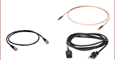
当社では各センサに付属するUSBケーブルの交換用ケーブルとしてUSB-ABL-60をご用意しております。このケーブルには、偶発的に外れることがないようにM2.5の固定用ネジが付いています。 そのほか、PM101のDA-15コネクタおよびPM101RのDE-9コネクタにおけるRS232シリアル信号出力ピンとPCのUSB端子を接続するための、USB Type-A -シリアルフライングリードアダプタCABRU15(別売り、下記参照)もご用意しています(注: PM101RにはDE-9コネクタを介して電源を供給することはできません)。

 ズーム
ズーム| Power Meter Interface Quick Comparisona | |||
|---|---|---|---|
| Item # | PM102 | PM102A | PM102U |
| Photo (Click to Enlarge) | | | |
| Connectors | Mini USB & DA-15 | Mini USB & SMA | Mini USB |
| Control / Digital Output | USB 2.0, RS232, or UART | USB 2.0 | USB 2.0 |
| Analog Output | Yes | Yes | No |
- 10以上のサーマルパワーセンサ、サーマル位置&パワーセンサに対応
- すべてのモデルはUSB 2.0による操作が可能
- モデル選択の要素
- UARTまたはRS232による操作
- アナログ出力
- 電力供給:USB(すべてのモデル)またはDA-15コネクタ(PM102のみ)
- Certificate of Calibration(校正証明書)が同梱
PM102シリーズのインターフェイスは、当社のCシリーズサーマルパワーセンサとサーマル位置&パワーセンサのすべてに対応します。当社のサーマルパワーセンサ全体で測定可能な光パワーの範囲は10 µW~200 Wです。また、当社のサーマル位置&パワーセンサは、ビーム位置と0.5 mW~50 Wの光パワーを同時に測定可能です。これに加えて、最大出力電圧1 Vのサーマル素子が接続可能です。すべてのインターフェイスはPCからmini-USBポート経由で操作や電力供給ができますが、一部のインターフェイスはUARTまたはRS232による操作やアナログ出力の機能を有します(右の表参照)。アナログ出力が可能なモデルは、追加の制御デバイスを必要とせずに、電源に接続するだけで単独での使用が可能になります。すべてのインターフェイスにはリセットボタンが付いており、システムを簡単に再起動できます。
各インターフェイス内にある不揮発性メモリには、ユニットのシャットダウンまたは再起動時において設定されていた波長、感度レンジ、出力構成などが保存されるため、長期間にわたる繰り返し測定に適しています。インターフェイスの使用中は、1000サンプル/秒という高速読み出しによりアクティブな信号のモニタリングができます。サーマルパワーセンサで精密な測定を行うために、これらのインターフェイスは2 mV~1 Vで9段階の電圧測定レンジを使用しています。これに対してPM100USBでは4段階のレンジしか使用していません(「仕様」タブ参照)。
これらのパワーメーターインターフェイスにセンサは付属しませんのでご注意ください。対応するセンサについては、下記のセンサに関する説明をご覧ください。当社では、パワーメーターインターフェイスの再校正サービスをご提供しています。詳細については当社までお問い合わせください。パワーメーターインターフェイスに対応する再校正の必要なセンサをお持ちの場合、センサの再校正費用のみでインターフェイスも含めて再校正することができます。
当社では各センサに付属するUSBケーブルの交換用ケーブルとしてUSB-ABL-60をご用意しております。このケーブルには、偶発的に外れることがないようにM2.5の固定用ネジが付いています。そのほか、PM102のDA-15コネクタにおけるRS232シリアル信号出力ピンとPCのUSB端子とを接続するための、USB Type-A -シリアルフライングリードアダプタCABRU15(別売り、下記参照)もご用意しています。

 ズーム
ズーム| Power Meter Interface Quick Comparisona | ||||
|---|---|---|---|---|
| Item # | PM103 | PM103A | PM103E | PM103U |
| Photo (Click to Enlarge) | | | | |
| Connectors | Mini USB & DA-15 | Mini USB & SMA | Ethernet (RJ45) & DMC 0,5/7 | Mini USB |
| Power Supply Connectors | USB or DA-15 | USB | Ethernet or DMC 0,5/7 | USB |
| Control / Digital Output | USB 2.0, RS232, or UART | USB 2.0 | Ethernet, RS232 | USB 2.0 |
| Analog Output | Yes | Yes | Yes | No |
- 20種類以上のフォトダイオードパワーセンサ、焦電エネルギーセンサに対応
- すべてのモデルはUSB 2.0による操作が可能(型番PM103Eを除く)
- モデル選択での留意点
- UARTまたはRS232による操作
- アナログ出力
- イーサネットによる操作
- 電源供給
- USB (型番PM103Eを除く)
- DA-15コネクタ(型番PM103のみ)
- イーサネットまたはDMC 0,5/7コネクタ(型番PM103Eのみ)
- Certificate of Calibration(校正証明書)が付属
PM103シリーズのインターフェイスは、当社のCシリーズのすべてのフォトダイオードパワーセンサおよび焦電エネルギーセンサに対応します。当社の標準フォトダイオードセンサ、薄型フォトダイオードセンサ、積分球センサおよびファイバ用センサ全体で測定可能な光パワーの範囲は100 pW~20 Wです。そのほか、増幅機能のない最大光電流10 mAのアノード接地型またはカソード接地型のフォトダイオードにもご使用いただけます。当社の焦電エネルギーセンサは、10 µJ~15 Jのエネルギーを測定できます。出力電圧20 mV~200 Vのエネルギーセンサにもご使用いただけます。すべてのインターフェイス (型番PM103Eを除く)はPCからmini-USBポート経由で操作や電力供給ができます。また、UARTやRS232による操作やアナログ出力が可能なインターフェイスもございます(右の表参照)。
PM103Eは、PCからの操作が可能ですが、ネットワークにPoE(Power over Ethernet)機能があればイーサネット接続で電源供給ができます。PoE機能がない場合には、デバイスに電源供給するために、5~36 VのDC電源をDMC 0,5/7コネクタのピン1とピン2(接地)に接続する必要があります。詳細は「ピン配列」タブをご覧ください。DMC 0,5/7コネクタにはRS232も接続できるため、シリアルインターフェイスでのデバイス操作も可能です。
アナログ出力が可能なモデルは、制御デバイスを使用しなくても、電源に接続するだけで単独での使用が可能になります。すべてのインターフェイスにはリセットボタンが付いており、システムを簡単に再起動できます。
ユニットのシャットダウンまたは再起動時には、設定されていた波長、感度レンジ、出力設定などがインターフェイス内にある不揮発性メモリに保存されるため、長期間にわたる繰り返し測定に適しています。インターフェイスの使用中は、100 kS/sの高速読み出しによりアクティブな信号のモニタリングができます。精密な測定を行うために、これらのインターフェイスは電圧測定範囲20 mV~200 Vに対して13段階の測定レンジを有し、電流測定範囲2 nA ~10 mAに対して21段階の測定レンジを有します。これに対してPM100USBでは4段階の電圧測定レンジと6段階の電流測定レンジしかありません(「仕様」タブ参照)。
インターフェイスPM103とPM103Eには、入出力構成等の設定可能な汎用のデジタルポートが2つ(DIO1、DIO2)が付いています(詳細は「ピン配列」タブ参照)。同様に、PM103Aには、SMAコネクタによる1つの補助的なデジタルポートDIO1があります。DIO1ポートは、100 kS/sモードでデータを読み込むときは、トリガ信号の入力用または出力用に設定可能です。DIO2ポートは、合否フラグに設定してリモート制御コマンドごとに問い合わせることもできます。
これらのパワーメーターインターフェイスにセンサは付属しませんのでご注意ください。対応するセンサについては、下記のセンサに関する説明をご覧ください。当社では、これらのインターフェイスの再校正サービスをご提供しています。詳細は当社までお問い合わせください。または再校正を必要とする対応センサをお持ちで、センサとパワーメーターインターフェイスの再校正を同時に行う場合、追加の費用無しでインターフェイスの再校正が可能です。
当社では各センサ(型番PM103Eを除く)に付属するUSBケーブルの交換用として、USB-ABL-60をご用意しています。このケーブルには、偶発的に外れることがないようにM2.5の固定用ネジが付いています。PM103Eには、長さ1.5 mのイーサネットパッチケーブルRJ45が付属しています。そのほか、USB Type-A-シリアルフライングリードアダプタCABRU15(別売り、下記参照)をご用意しています。これを使用すると、PM103のDA-15コネクタやPM103EのDMC 0,5/7コネクタのRS232シリアル信号出力ピンを、PCのUSB端子に接続することができます。 また、USBアダプタCABRU15を経由して、PM103とPM103Eに電源供給することも可能です。

 ズーム
ズーム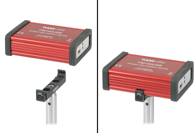
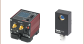
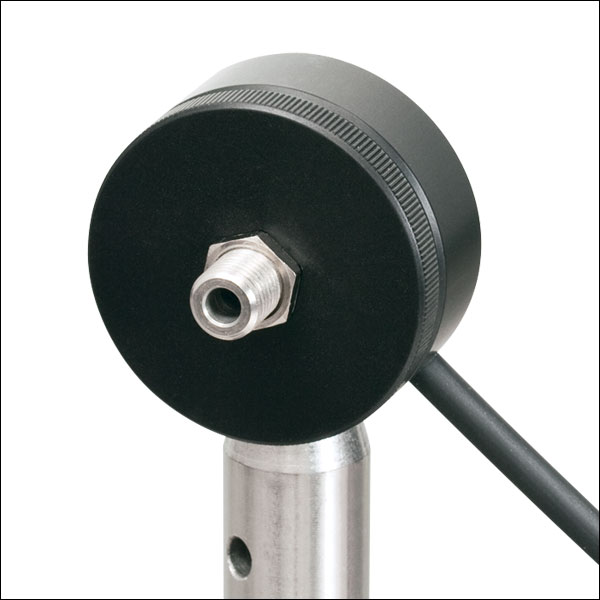
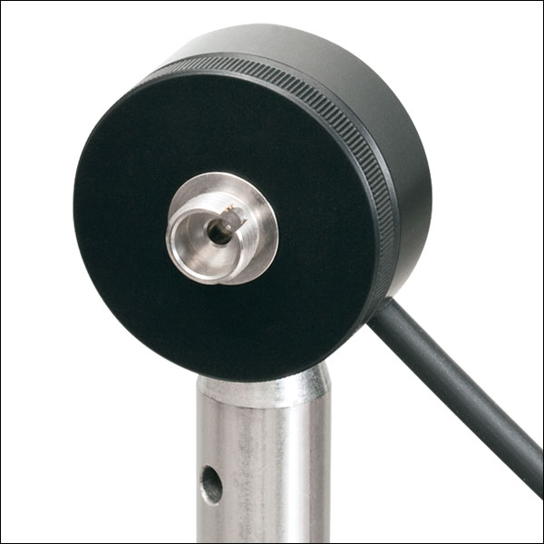
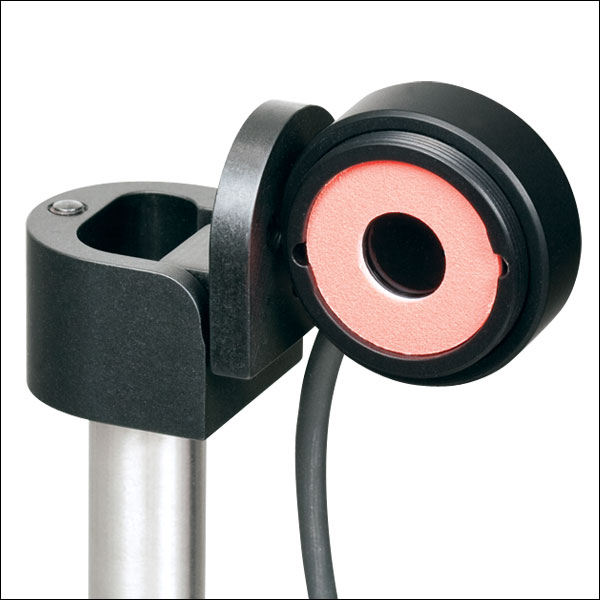
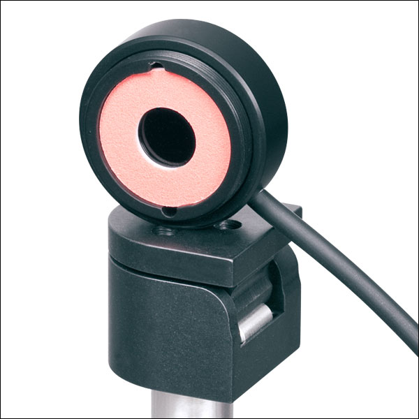
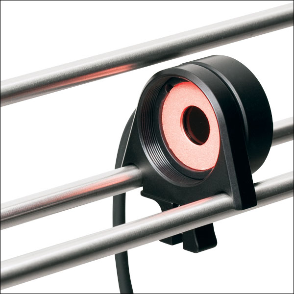
Click for Details
クランプECM225を使用してポストに取り付けられたPM100USB
- 30種類以上のフォトダイオードセンサ、サーマルセンサ、焦電センサに対応
- USB経由での制御および電源供給
- Certificate of Calibration(校正証明書)の添付
パワー&エネルギーメーターインターフェイスPM100USBは、当社のすべてのCシリーズのフォトダイオードセンサ、サーマルセンサ、焦電センサ(高速焦電センサES408Cを除く)に対応します。当社のCタイプの標準フォトダイオードセンサ、薄型フォトダイオードセンサ、積分球センサおよびファイバ用センサは、100 pW~20 Wの光パワーを測定可能です。一方、当社のサーマルパワーセンサ全体で測定可能な光パワーの範囲は10 µW~200 Wです。Cシリーズの焦電エネルギーセンサは、10 µJ~15 Jのエネルギおよび最大2 kHzまでの繰返し周波数を測定可能です。注:最大10 kHzまでの繰返し周波数に対応するセンサES408C(下記掲載)は、最大3 kHzの繰返し周波数に対応するインターフェイスPM100USBとのご使用にはお勧めいたしません。これに加えて、陽極または陰極接地の増幅無しのフォトダイオード(光電流の最大が5 mA)や最大出力電圧1 Vのサーマル素子、または出力電圧100 mV~100 Vのエネルギーセンサが接続可能です。
このインターフェイスは、mini-USBポートを介してPCによる操作が可能です。読み出し速度は300サンプル/秒で、インターフェイスの使用中でもアクティブに信号のモニタリングができます。
PM100USBにはセンサは付属していませんのでご注意ください。対応するセンサについては、下記に記載しています。当社では、PM100USBの再校正サービスをご提供しています。詳細については当社までお問い合わせください。なお、PM100USBに対応する再校正の必要なセンサをお持ちの場合、センサの再校正費用のみでPM100USBも含めて再校正することができます。

 ズーム
ズーム
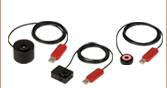
- USB 2.0 Type Aーシリアルコンバータ、片端は4本の色分けされたØ1.05 mmフェルール
- デバイスのRS232出力信号をPCに接続
- ケーブル長: 1.5 m
USB A - シリアルフライングリードアダプターケーブルCABRU15は、当社製品(パワーメーターインターフェイスやコンソール等)のRS232信号出力ピンをPCに接続するのに使用します。対応するデバイスのRS232ピン配列については「ピン配列」タブをご覧ください。 このコネクタには、Windows、MACおよびLinuxなどのOSとのインターフェイスのために、USB信号とTTLシリアル信号およびRS232信号との間のレベルコンバータ回路が内蔵されています。
Click to Enlarge
S120Cと簡単脱着式マウントCP44F
- 一般的な光パワー測定用
- センサのアライメントを容易にするビュワーターゲット付き
- センサ開口部:Ø9.5 mm
- センサ、保護キャップ、赤外域用ターゲットが付属
- ファイバーアダプタも別売りでご用意(下記参照)
- 詳細は、こちらをご参照ください。
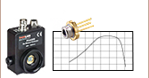
この標準型フォトダイオードパワーセンサは、UVから近赤外までの低いパワーのコヒーレント光/インコヒーレント光の測定にご使用いただけます。NISTトレーサブル、校正済みで、アライメントが容易になるビュワーターゲットを搭載しており、電磁波干渉に対する遮蔽機能が強化され、過熱警報機能、Ø9.5 mmの大きな開口が特長です。30 mmケージシステム、Ø12 mm~Ø12.7 mm(Ø1/2インチ)ポスト、SM1レンズチューブに取付け可能で、自由空間やファイバ出力光源の測定にも適しています。
当社ではこれらのセンサに対して再校正サービスをご提供しております。再校正サービスの詳細は当社までお問い合わせください。
| Item #a | S120VC | S120C | S121C | S122C |
|---|---|---|---|---|
| Sensor Image (Click the Image to Enlarge) |
|
|
|
|
| Aperture Size | Ø9.5 mm | |||
| Wavelength Range | 200 - 1100 nm | 400 - 1100 nm | 400 - 1100 nm | 700 - 1800 nm |
| Power Range | 50 nW - 50 mW | 500 nW - 500 mW | 50 nW - 40 mW | |
| Detector Type | Si Photodiode (UV Extended) | Si Photodiode | Ge Photodiode | |
| Linearity | ±0.5% | |||
| Resolutionb | 1 nW | 10 nW | 2 nW | |
| Measurement Uncertaintyc | ±3% (440 - 980 nm) ±5% (280 - 439 nm) ±7% (200 - 279 nm, 981 - 1100 nm) | ±3% (440 - 980 nm) ±5% (400 - 439 nm) ±7% (981 - 1100 nm) | ±5% | |
| Responsivityd (Click for Plot) |  Raw Data |  Raw Data |  Raw Data |  Raw Data |
| Coating/Diffuser | Reflective ND (OD1.5)e | Reflective ND (OD1)f | Reflective ND (OD2)g | Absorptive ND (Schott NG9) |
| Head Temperature Measurement | NTC Thermistor 4.7 kΩ | |||
| Housing Dimensions | Ø30.5 mm x 12.7 mm | |||
| Cable Length | 1.5 m | |||
| Post Mountinge,f,g | Universal 8-32 / M4 Tap, Post Not Included | |||
| Aperture Thread | External SM1 (1.035"-40) | |||
| Compatible Fiber Adapters | S120-FC2, S120-FC, S120-APC2, S120-APC, S120-SMA, S120-ST, S120-LC, and S120-SC (Not Included) | |||
| Compatible Consoles | PM400, PM100D, PM100A, and PM5020 | |||
| Compatible Interfaces | PM101, PM101A, PM101R, PM101U, PM103, PM103A, PM103E, PM103U, and PM100USB | |||

- 限られたスペースでの光パワー測定に
- 薄型設計:センサの厚さ5 mm
- センサ開口部:Ø9.5 mm
- スライド式のNDフィルタがセンサのパワーレンジを自動調整
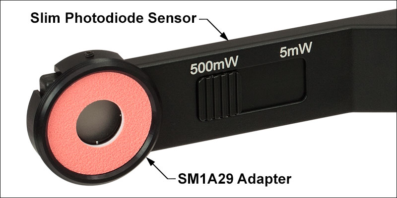
- VIS/IRターゲットとSM1外ネジ付きアダプタSM1A29を別途ご用意(詳細はこちら)
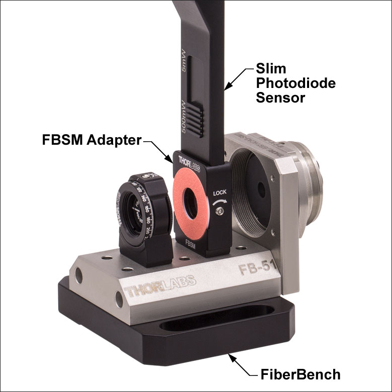
- FiberBenchシステム用VIS/IRターゲット付きマウントFBSMも別途ご用意(詳細はこちら)
- 詳細はこちらをご参照ください。
こちらの薄型フォトダイオードパワーセンサは、限られたスペースにおいて光パワーが測定できるように設計されています。センサの厚さが僅か5 mmなので、近接配置した光学素子の間やケージシステムの中など、標準のパワーメータを設置することのできない場所でもご使用になれます。NISTトレーサブル、校正済みで、Ø9.5 mmの大きな開口も特長です。また、スライド式のNDフィルタが付いているため、コンパクトなデバイス1つで2つのパワー範囲を測定可能です。
S130シリーズのパワーセンサに、別売りのアダプタSM1A29を2つの止めネジ(セットスクリュ)で取り付けることにより、ファイバーアダプタ、遮光体、フィルタなど、SM1ネジ付き部品を取り付けることができます。マウントFBSMによりS130シリーズのパワーセンサがFiberBenchシステムに垂直方向に取り付けられるため、安定かつ最小の設置面積の取り付けとなります。
当社ではこれらのセンサに対して再校正サービスをご提供しております。詳細については当社までお問い合わせください
| Item #a | S130VC | S130C | S132C | |
|---|---|---|---|---|
| Sensor Image (Click the Image to Enlarge) |
|
|
| |
| Aperture Size | Ø9.5 mm | |||
| Wavelength Range | 200 - 1100 nm | 400 - 1100 nm | 700 - 1800 nmb | |
| Power Range (with Filter) | 500 pW - 0.5 mWc (Up to 50 mW)c | 500 pW - 5 mW (Up to 500 mW) | 5 nW - 5 mW (Up to 500 mW) | |
| Detector Type | Si Photodiode (UV Extended) | Si Photodiode | Ge Photodiode | |
| Linearity | ±0.5% | |||
| Resolution | 100 pWd | 1 nWe | ||
| Measurement Uncertaintyf | ±3% (440 - 980 nm) ±5% (280 - 439 nm) ±7% (200 - 279 nm, 981 - 1100 nm) | ±3% (440 - 980 nm) ±5% (400 - 439 nm) ±7% (981 - 1100 nm) | ±5% | |
| Responsivityg (Click for Plot) | Raw Data | Raw Data | Raw Data | |
| Coating/Diffuser | Reflective ND (OD1.5)c | Reflective ND (OD2)h | Absorptive ND (Schott NG9/KG3)b | |
| Housing Dimensions | 150 mm x 19 mm x 10 mm; 5 mm Thickness on Sensor Side | |||
| Cable Length | 1.5 m | |||
| Post Mounting | 8-32 and M4 Taps | |||
| Adapters (Not Included) | SM1A29: Add SM1 Thread and Viewing Target to Aperture Fiber Adapters Compatible with SM1A29 Adapter: S120-FC2, S120-FC, S120-APC2, S120-APC, S120-SMA, S120-ST, S120-SC, and S120-LC FBSM: Integrate Sensor into FiberBench Setups | |||
| Compatible Consoles | PM400, PM100D, PM100USB, PM100A, and PM5020 | |||
| Compatible Interfaces | PM101, PM101A, PM101R, PM101U, PM103, PM103A, PM103E, PM103U, and PM100USB | |||
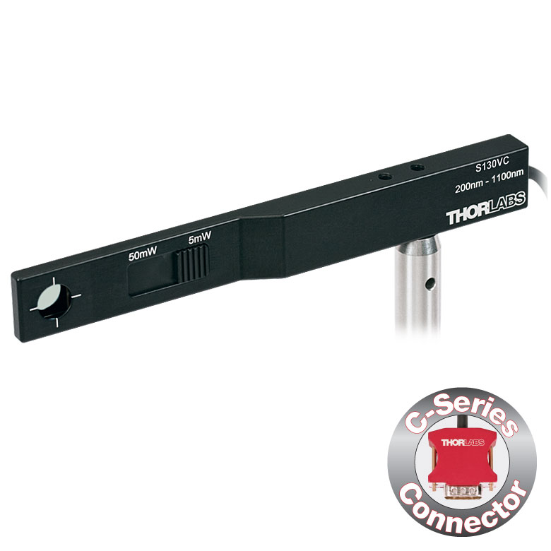
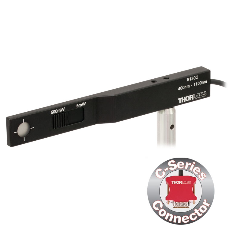
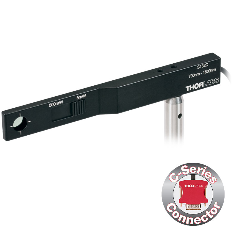
| Item #a | S116C | |
|---|---|---|
| Sensor Image (Click the Image to Enlarge) |
| |
| Aperture Size | Ø6 mm | |
| Wavelength Range | 400 - 1100 nm | |
| Power Range | 20 nW - 50 mW | |
| Detector Type | Si Photodiode | |
| Linearity | ±0.5% | |
| Resolution | 1 nWb | |
| Measurement Uncertaintyc | ±3% (451 - 1000 nm) ±5% (400 - 450 nm, 1001 - 1100 nm) | |
| Responsivityd (Click for Plot) | Raw Data | |
| Coating/Diffuser | Absorptive ND (NG9) | |
| Housing Dimensions (L x W x T) | 70.0 mm x 11.0 mm x 8.9 mm; 10.0 mm Width and 4.5 mm Thickness on Sensor Side | |
| Active Detector Area | 7 mm x 7 mm | |
| Cable Length | 1.5 m | |
| Mounting Threads | 2 Universal 8-32 / M4 Taps (One on the Back, One on the Bottom), Posts Not Included | |
| Adapters (Not Included) | SM05A29: Add SM05 Thread to Aperture Fiber Adapters Compatible with SM05A29 Adapter: PM20-FC2, PM20-FC, PM20-APC2, PM20-APC, PM20-SMA, PM20-ST, PM20-SC, and PM20-LC | |
| Compatible Consoles | PM400, PM100D, PM100A, and PM5020 | |
| Compatible Interfaces | PM101, PM101A, PM101R, PM101U, PM103, PM103A, PM103E, PM103U, and PM100USB | |
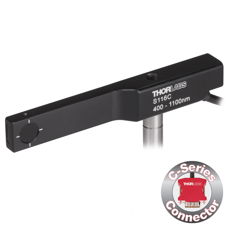
- 16 mmケージシステムなどの狭いスペースでの光パワー測定用
- 波長範囲:400~1100 nm
- 超薄型設計:センサ部の幅10.0 mm、厚さ4.5 mm
- シリコン(Si)フォトダイオード、センサ開口Ø6 mm
- 低パワーレーザ光のパワー測定用
- ポスト取付け用のM4タップ穴
- SM05外ネジ付きアダプタSM05A29は別売りでご用意(詳細はこちら)
- 詳細についてはこちらの製品紹介ページをご覧ください。
コンパクト薄型フォトダイオードパワーセンサS116Cは、スペースやアクセス性が制限された場面でも光パワーが測定できるように設計されています。厚さ4.5 mmのフォトダイオードセンサは、16 mmケージシステムのケージロッドの間(下の写真参照)や、スロット付きØ12 mm~Ø12.7 mm(Ø1/2インチ)レンズチューブ(型番SM05L20CおよびSM05L30C)の側面の穴から挿入することができます。このセンサの開口径はØ6 mmです。
パワーセンサS116Cに、別売りのアダプタSM1A29を2本の1.3 mm六角止めネジ(セットスクリュ)で取り付けると、ファイバーアダプタ、遮光体、フィルタなどのSM05ネジ付き部品を取り付けることができます。アダプタを取り付けたパワーセンサS116Cの写真が下でご覧いただけます。
各センサはNISTまたはPTBトレーサブル校正データとともに発送いたします。ここに含まれるデータは、校正対象センサのスペクトル範囲に対応する、認定された参照用ダイオードを利用して決定されています。当社では、フォトダイオードパワーセンサの再校正サービスをご提供しています。詳細は当社までお問い合わせください。
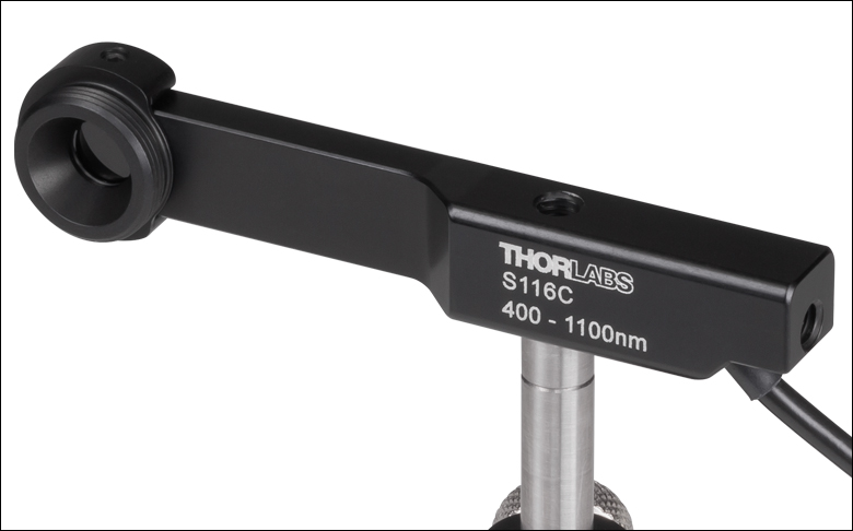
| Item #a | S170C | S171C | |||
|---|---|---|---|---|---|
| Sensor Image (Click Image to Enlarge) | 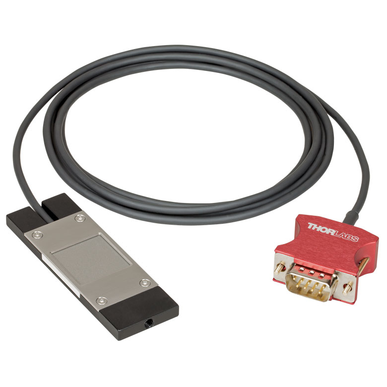 |  | |||
| Overall Dimensions | 76.0 mm x 25.2 mm x 5.0 mm (2.99" x 0.99" x 0.20") | ||||
| Active Detector Area | 18 mm x 18 mm | ||||
| Input Aperture | 20 mm x 20 mm | ||||
| Wavelength Range | 350 - 1100 nm | 400 - 1100 nm | |||
| Optical Power Working Range | 10 nW - 150 mW | 1 nW - 15 mW | |||
| Detector Type | Silicon Photodiode | ||||
| Linearity | ±0.5% | ||||
| Resolution | 1 nWb | 0.5 pWc | |||
| Measurement Uncertaintyd | ±3% (440 - 980 nm) ±5% (350 - 439 nm) ±7% (981 - 1100 nm) | ±3% (440 - 980 nm)e ±5% (400 - 439 nm)e ±7% (981 - 1100 nm)e | |||
| Responsivityf (Click for Plot) | Raw Data | Raw Data | |||
| Neutral Density Filter | Reflective (OD 1.5) | Absorptive (OD 0.4) | |||
| Cable Length | 1.5 m | ||||
| Mounting Thread | Universal 8-32 / M4 Tap, Post Not Included | ||||
| Compatible Consoles | PM400, PM100D, PM100A, and PM5020 | ||||
| Compatible Interfaces | PM101, PM101A, PM101R, PM101U, PM103, PM103A, PM103E, PM103U, and PM100USB | ||||
- 顕微鏡の試料面での光パワーの計測用に設計
- 大きな受光面18 mm x 18 mmのシリコンフォトダイオード
- センサ筐体の寸法 76.0 mm x 25.2 mm x 5.0 mm
- 内部反射を防ぐ屈折率マッチングジェルを採用
- コネクタに以下の情報を保存
- センサーデータ
- NISTまたはPTBにトレーサブルな校正データ
- M4タップ穴を利用してポストに取付け可能
このシリコンフォトダイオードが取付けられた顕微鏡用スライドパワーセンサーヘッドは、顕微鏡システム内の試料面における光パワーを測定するように設計されています。S170Cは波長範囲350 nm~1100 nmに感度を有し、10 nW~150 mWの光パワーを測定できます。S171Cは波長範囲400 nm~1100 nmに感度を有し、1 nW~15 mWの光パワーを測定できます。センサーヘッドの外形寸法76.0 mm x 25.2 mmは標準の顕微鏡用スライドと同じで、多くの標準的な正立および倒立顕微鏡にお使いいただけます。
フォトダイオードの受光面の大きさは18 mm x 18 mmです。このフォトダイオードは密封された筐体に収納されており、その前面にはNDフィルタが付いています。NDフィルタの表面の周囲には段差があり、それにより20 mm x 20 mm大きさのくぼみができています。このくぼみには標準的な顕微鏡用カバースリップを入れることができます。液浸材(水、グリセロール、油)は、NDフィルタの上のこのくぼみ内に直接つけることができます。または、クリーニングを容易にするために、最初にカバースリップを挿入することもできます。フォトダイオードとNDフィルタの間の隙間には屈折率マッチングジェルが充填されています。これは、高開口数(NA)の対物レンズを油浸または水浸で使用したときに、大きな測定誤差の原因となる内部反射を防止するためです。
センサ筐体の背面には、ビームのアライメントや集光の作業を補助するためにグリッドがレーザ刻印されています。標準的な顕微鏡では、このグリッドを用いてビームをアライメントした後、センサーヘッドを反転させて対物レンズに向ければ光パワーの測定を行うことができます。倒立顕微鏡の場合は、透過照明光をオンにしてディテクタ筐体のグリッドとビームを合わせれば、センサの中心が対物レンズの正面にきます。そのほか、NDフィルタの拡散面を集光面として使用することもできます。
センサを損傷させないために、ビームが集光されない位置にセンサを配置することをお勧めします。ビームのスポットサイズ内のどの位置においても、最大平均パワー密度(Max Average Power Density、「仕様」タブ参照)を超えないことが重要です。
各センサにはNISTまたはPTBにトレーサブルな校正データが添付されます。それらのデータは、各センサの試験に使用されたフォトダイオードの校正証明書のデータと整合しています。センサ仕様とNISTまたはPTBにトレーサブルな校正データがセンサーコネクタ内の不揮発性メモリに保存されており、当社の最新のパワーメーターコンソールで読み出すことができます。精度と性能を維持するために定期的な再校正をお勧めします。校正頻度は用途にもよりますが、通常1年程度です。当社では、再校正サービスを提供しております。詳細は当社までお問い合わせください。
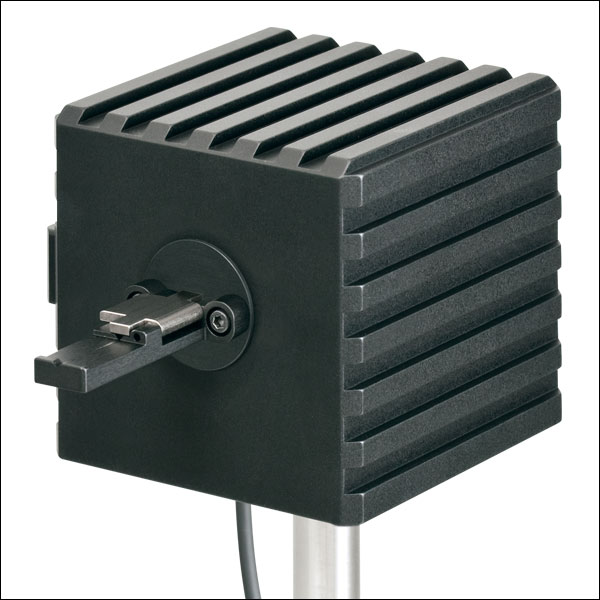
Click to Enlarge
ファイバ素線用アダプタS140-BFA(別売り)を取り付けたS142C
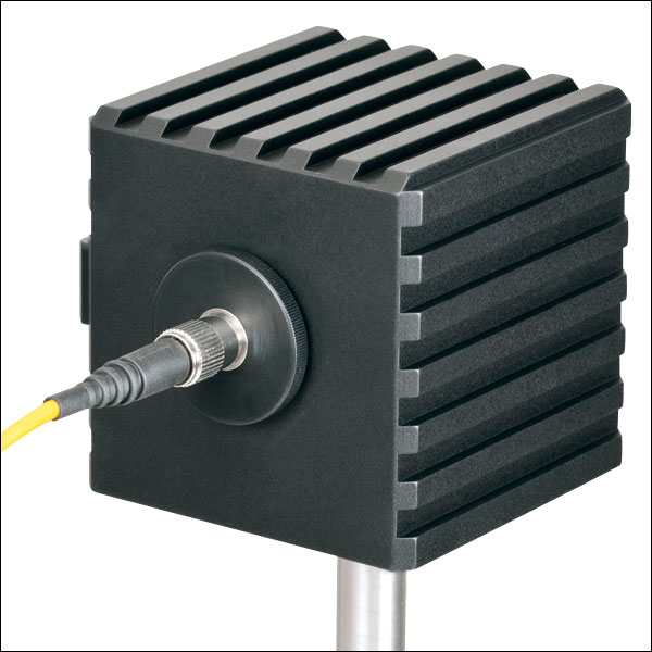
Click to Enlarge
ファイバーアダプタS120-FC(付属)を取り付けたS142C
- ビーム形状や入射角の影響を受けない測定が可能
- 積分球方式により光損失を最小に抑えた拡散板として機能
- センサの入射開口径:Ø5 mm、Ø7 mm、Ø12 mmまたはØ22 mm
- 開口径≤Ø12 mmの積分球には取外し可能なファイバーアダプタS120-FC(FC/PCまたはFC/APCの取付けが可能)が付属
- 開口径≤Ø12 mmの積分球には、終端処理済みファイバ用およびファイバ素線用のアダプタ(下表参照)の取付けが可能
- 詳細はこちらの製品ページをご覧ください。
積分球フォトダイオードパワーセンサは、入射するビームの均一性、広がり角、形状、入射角などに依存せずにパワーを測定するのに適しており、ファイバ光源からの光や光軸から外れた自由空間光などのパワー測定用として優れています。電磁干渉を抑制するためにシールドが強化されており、またセンサの加熱による損傷や測定エラーを防止するために過熱警告センサが付いています。
当社の積分球は、可視~近赤外の波長域用に設計されています。350~2500 nm用のセンサーヘッドには、Zenith® PTFE製のØ25.4 mm(Ø1インチ)またはØ50.8 mm(Ø2インチ)の単一の球が使用されており、入射開口部周辺での反射光を最小限に抑えるために筐体は黒色になっています。波長範囲350~1100 nm用の光検出センサとしてはシリコン(Si)フォトダイオードを、波長範囲800~1700 nm、900~1650 nm、または1200~2500 nm用の光検出センサとしてはInGaAsフォトダイオードを使用しています。
2.9~5.5 µm用の積分球S180Cでは、金メッキされたØ20 mmの球を2つ接続して使用しています。1つめの球に入射ポートが付いており、MCT (HgCdTe)ディテクタ用のポートは2つ目の球に付いています。2つの球を用いる方式では、単一の球を用いる方式と比べると、ディテクタが入射光に直接晒されないように効果的に遮光できるだけでなく、内部の球の表面積を最小限に抑えることもできるため、検出器としての感度が向上します。この方式では、バッフルやその他の遮光機構を使用しなくても、フォトダイオードへの直接入射光を効果的に遮蔽できるため、入射角、広がり角、ビーム形状などによる測定への影響を低減できます。
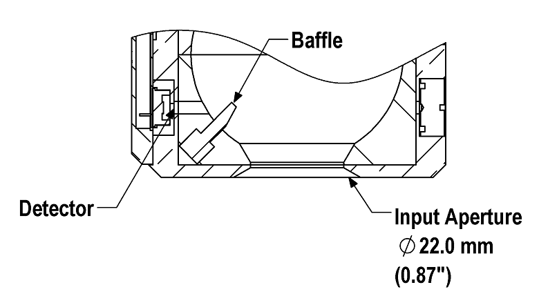
Click to Enlarge
S142CLとS145CLでは、ディテクタに直接光が入射しないようにバッフルを用いて遮光しています。
開口径が Ø5 mm、Ø7 mmまたはØ12 mmの積分球には大きな受光面積の検出器が付いており、また付属のファイバーアダプタS120-FCを取り付けられるSM1外ネジ付きアダプタが付いています。これらのセンサの検出器の受光面積が大きいため、付属のファイバーアダプタS120-FCにはFC/PCまたはFC/APCコネクタ付きファイバを接続することができます。SM1外ネジ付きアダプタはサイズ1のスクリュードライバを使用して取り外せるため、コンポーネントをウィンドウの近くに設置することができます。
積分球S142CLとS145CLの入射開口径はØ22 mmと大きいですが、積分球内のバッフルでフォトダイオードに光が直接入射しないように遮光しています。大きな開口径とバッフルの組み合わせにより、LEDやVCSELのような面積と発散角の大きな光源からの光も測定可能です。ディテクタの入射面には、30 mmケージシステム部品を取り付けるための4つの#4-40ネジが付いています。また、ご要望により、センサーヘッドに第2あるいは第3のポートを付けることも可能です。詳細は当社までお問い合わせください。
各センサにはNISTまたはPTBにトレーサブルな校正データが付いています。それらのデータは、各センサの試験に使用されたフォトダイオードの校正証明書のデータと同じです。NISTまたはPTBにトレーサブルなデータはセンサーコネクタ内に保存されています。当社では、フォトダイオードパワーセンサの再校正サービスをご提供しています。詳細は当社までお問い合わせください。
| Item #a | S140C | S142C | S142CL | S144C | S145C | S145CL | S146C | S148C | S180C | |
|---|---|---|---|---|---|---|---|---|---|---|
| Sensor Image (Click the Image to Enlarge) | 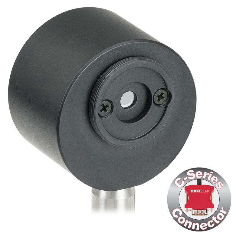 | 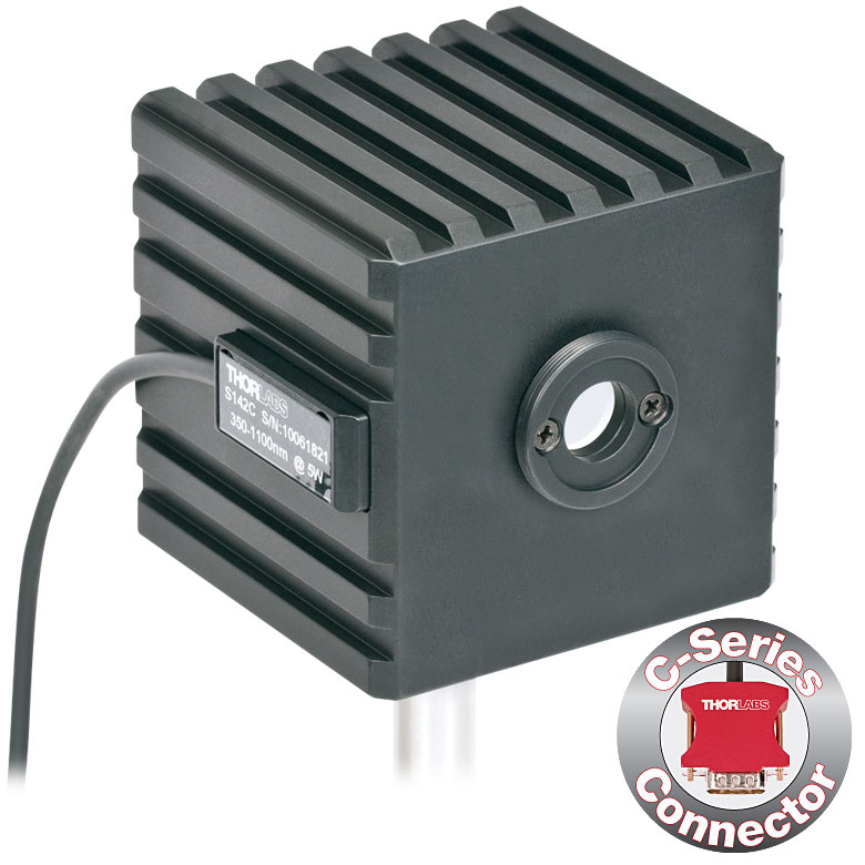 | 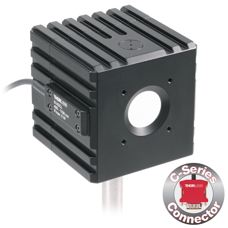 |  | 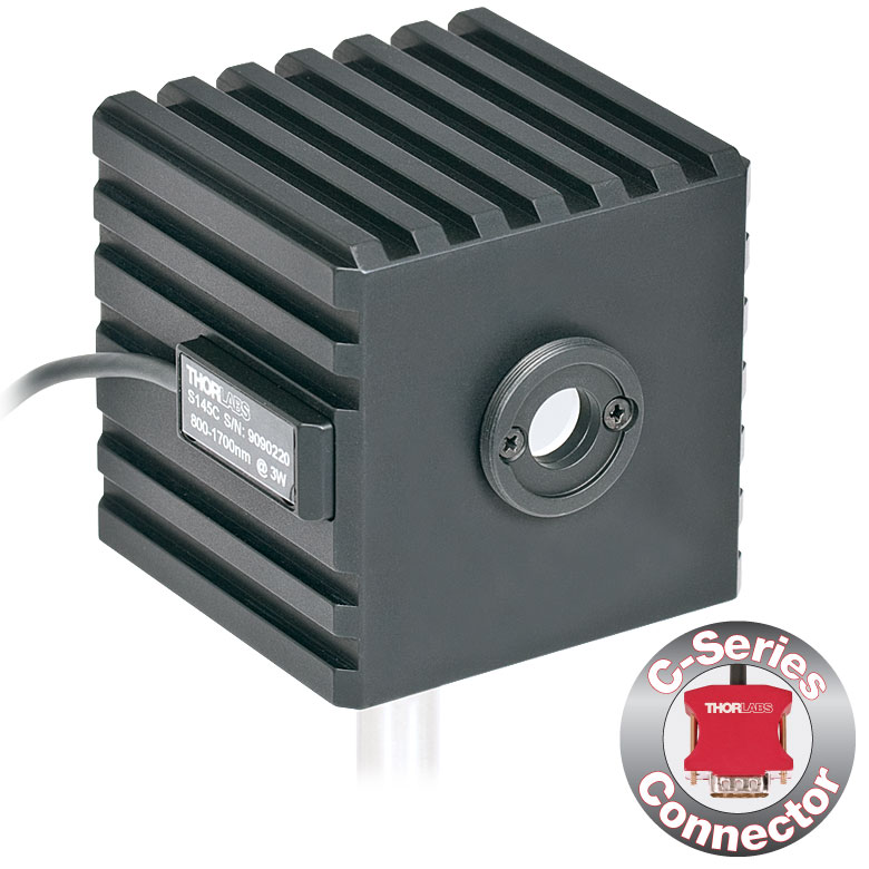 | 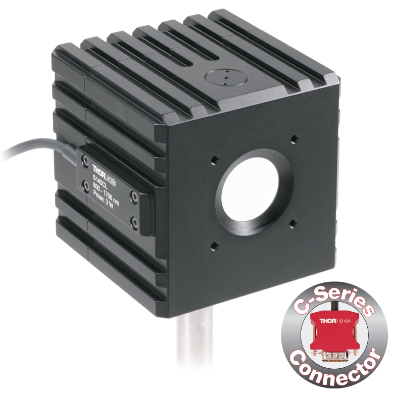 | 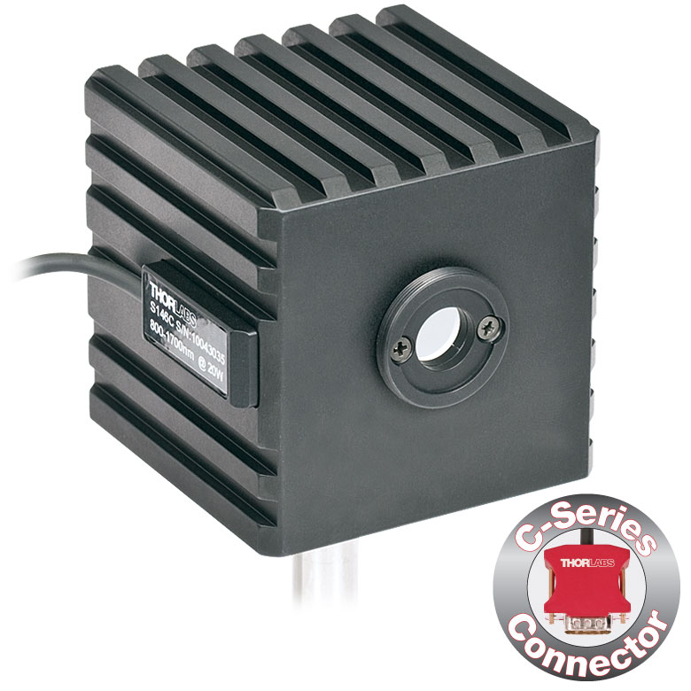 | | 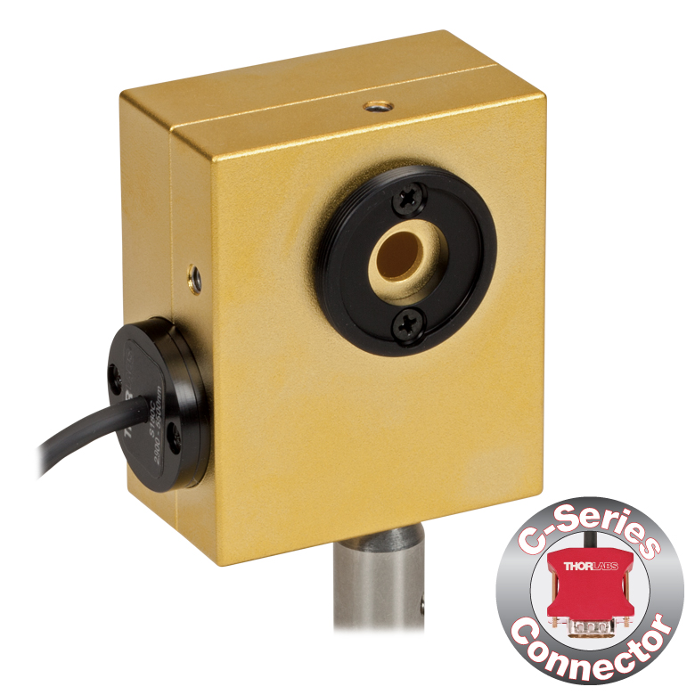 | |
| Aperture Size | Ø5 mm | Ø12 mm | Ø22 mm | Ø5 mm | Ø12 mm | Ø22 mm | Ø12 mm | Ø5 mm | Ø7 mm | |
| Wavelength Range | 350 - 1100 nm | 400 - 1100 nm | 800 - 1700 nm | 900 - 1650 nm | 1200 - 2500 nm | 2.9 µm - 5.5 µm | ||||
| Power Range | 1 µW - 500 mW | 1 µW - 5 W | 10 µW - 5 W | 1 µW - 500 mW | 1 µW - 3 W | 10 µW - 3 W | 10 µW - 20 W | 1 µW - 1 W | 1 µW - 3 W | |
| Detector Type | Si Photodiode | Si Photodiode with Baffle | InGaAs Photodiode | InGaAs Photodiode with Baffle | InGaAs Photodiode | Extended InGaAs Photodiode | MCT (HgCdTe) Photodiode | |||
| Linearity | ±0.5% | |||||||||
| Resolutionb | 1 nW | 10 nW | 1 nW | 10 nW | 1 nW | 10 nW | ||||
| Measurement Uncertaintyc,d | ±3% (440 - 980 nm) ±5% (350 - 439 nm) ±7% (981 - 1100 nm) | ±3% (440 - 980 nm) ±5% (400 - 439 nm) ±7% (981 - 1100 nm) | ±5% | |||||||
| Responsivitye (Click for Plot) |  Raw Data |  Raw Data |  Raw Data |  Raw Data |  Raw Data |  Raw Data |  Raw Data |  Raw Data | Raw Data | |
| Integrating Sphere Material (Size) | Zenith® PTFE (Ø1") | Zenith® PTFE (Ø2") | Zenith® PTFE (Ø1") | Zenith® PTFE (Ø2") | Zenith® PTFE (Ø1") | Gold Plating (Two Ø20 mm Spheres) | ||||
| Head Temperature Measurement | NTC Thermistor 4.7 kΩ | |||||||||
| Housing Dimensions | Ø45 mm x 30.5 mm | 70 mm x 74 mm x 70 mm | Ø45 mm x 30.5 mm | 70 mm x 74 mm x 70 mm | Ø45 mm x 30.5 mm | 59.0 mm x 50.0 mm x 28.5 | ||||
| Active Detector Area | 3.6 mm x 3.6 mm | Ø2 mm | Ø3 mm | Ø1 mm | Ø1 mm | 1 mm x 1 mm | ||||
| Cable Length | 1.5 m | |||||||||
| Mounting Thread | Separate 8-32 and M4 Taps, Posts Not Included | Universal 8-32 / M4 Thread, Post Not Included | Separate 8-32 and M4 Taps, Posts Not Included | Universal 8-32 / M4 Thread, Post Not Included | Separate 8-32 and M4 Taps, Posts Not Included | Universal | ||||
| Aperture Thread | Included Adapter with SM1 (1.035"-40) External Thread | None | Included Adapter with SM1 (1.035"-40) External Thread | None | Included Adapter with SM1 (1.035"-40) External Thread | |||||
| Compatible Fiber Adapters | S120-FC (Included) S120-FC2, S120-APC2, S120-APC, S120-SMA, S120-ST, S120-SC, S120-LC, S120-25, and S140-BFA (Not Included) | None | S120-FC (Included) S120-FC2, S120-APC2, S120-APC, S120-SMA, S120-ST, S120-SC, S120-LC, S120-25, and S140-BFA (Not Included) | None | S120-FC (Included) S120-FC2, S120-APC2, S120-APC, S120-SMA, S120-ST, S120-SC, S120-LC, S120-25, and S140-BFA (Not Included) | |||||
| Compatible Consoles | PM400, PM100D, PM100A, and PM5020 | |||||||||
| Compatible Interfaces | PM101, PM101A, PM101R, PM101U, PM103, PM103A, PM103E, PM103U, and PM100USB | |||||||||

Click to Enlarge
センサS150CとFCケーブルを付けたPM100D
- ファイバ接続による光パワー測定用
- 小型センサがコネクタ内部に収納
- 現場や研究室で使い易い設計
- ファイバーアダプタPM20-FCが付属
- センサS150CおよびS151CにはアダプタPM20-SMAも付属
- 対応するFC/APC、LC/PC、SC/PC、 ST®*ファイバーアダプタもご用意(下表参照)
- 詳細はこちらをご参照ください。
S15xCシリーズのファイバ用小型フォトダイオードパワーセンサは、様々なファイバ出力光源のパワー測定用に設計されています。小型のセンサがパワーメーターコネクタに収納されており、ファイバ入力でNISTトレーサブルなデータ測定を実現します。標準的なFCアダプタ(S150CおよびS151CではSMAアダプタも同様)を、簡単に他の標準的なファイバーアダプタと取り換えることもできます。
当社ではこれらのセンサに対して再校正サービスをご提供しております。詳細については当社までお問い合わせください。
*ST®はLucent Technologies社の登録商標です。
| Item #a | S150C | S151C | S154C | S155C |
|---|---|---|---|---|
| Sensor Image (Click the Image to Enlarge) |
|
|
|
|
| Included Connectors | FCb & SMA | FCb | ||
| Wavelength Range | 350 - 1100 nm | 400 - 1100 nm | 800 - 1700 nm | |
| Power Range | 100 pW to 5 mW (-70 dBm to +7 dBm) | 1 nW to 20 mW (-60 dBm to +13 dBm) | 100 pW to 3 mW (-70 dBm to +5 dBm) | 1 nW to 20 mW (-60 dBm to +13 dBm) |
| Detector Type | Si Photodiode | InGaAs Photodiode | ||
| Linearity | ±0.5% | |||
| Resolutionc | 10 pW (-80 dBm) | 100 pW (-70 dBm) | 10 pW (-80 dBm) | 100 pW (-70 dBm) |
| Measurement Uncertaintyd | ±3% (440 - 980 nm) ±5% (350 - 439 nm) ±7% (981 - 1100 nm) | ±3% (440 - 980 nm) ±5% (400 - 439 nm) ±7% (981 - 1100 nm) | ±5% | |
| Responsivityf (Click for Details) |  Raw Data |  Raw Data |  Raw Data |  Raw Data |
| Coating/Diffuser | N/A | Absorptive ND (Schott NG3) | N/A | |
| Head Temperature Measuremente | NTC Thermistor 3 kΩ | |||
| Aperture Thread | External SM05 (0.535"-40) | |||
| Fiber Adapters | Included: PM20-FC and PM20-SMA Optional: PM20-FC2, PM20-APC2, PM20-APC, PM20-ST, PM20-SC, and PM20-LC | Included: PM20-FC Optional: PM20-FC2, PM20-APC2, PM20-APC, PM20-SMA, PM20-ST, PM20-SC, and PM20-LC | ||
| Compatible Consoles | PM400, PM100D, PM100A, and PM5020 | |||
| Compatible Interfaces | PM101, PM101A, PM101R, PM101U, PM103, PM103A, PM103E, PM103U, and PM100USB | |||

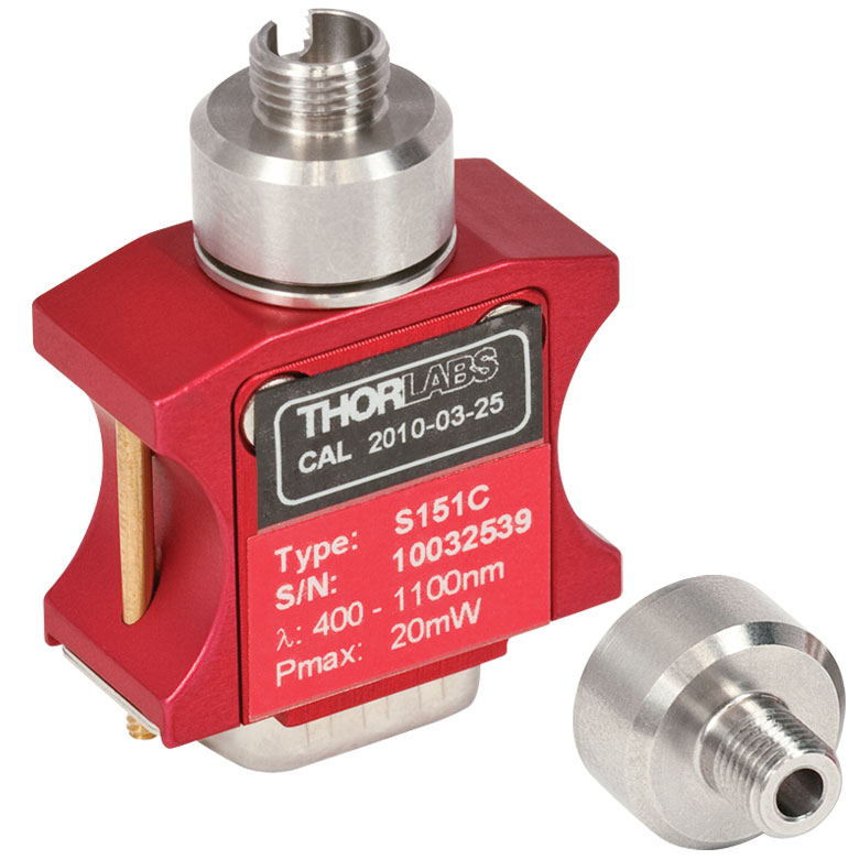
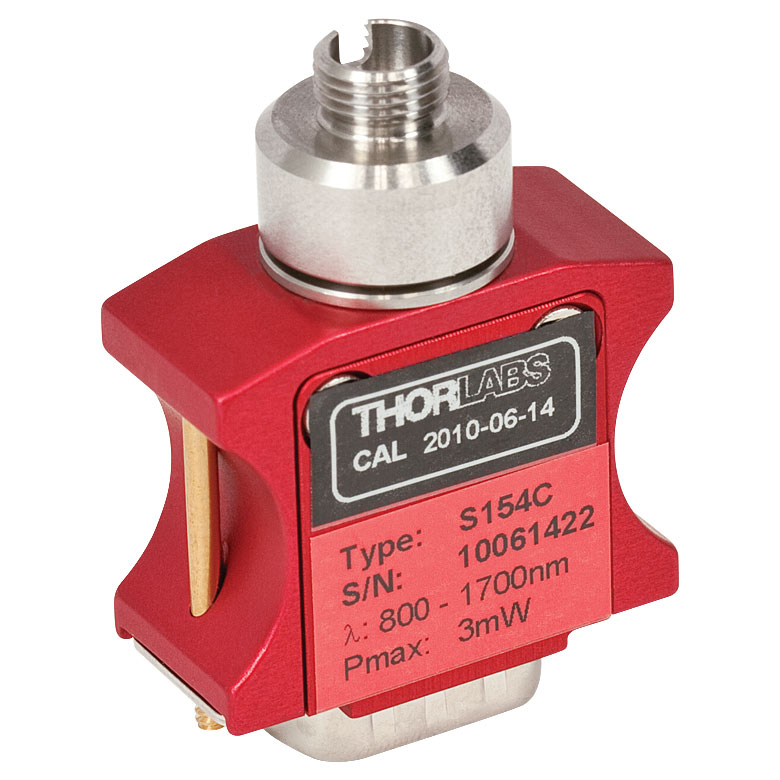

| Item #a | S175C |
|---|---|
| Sensor Image (Click Image to Enlarge) |  |
| Active Detector Area | 18 mm x 18 mm |
| Wavelength Range | 0.3 - 10.6 µm |
| Power Range | 100 µW - 2 W |
| Detector Type | Thermal Surface Absorber (Thermopile) |
| Linearity | ±0.5% |
| Resolutionb | 10 µW |
| Measurement Uncertaintyc | ±3% @ 1064 nm; ±5% @ 300 nm - 10.6 µm |
| Response Time | 3 s (< 2 s from 0 to 90%) |
| Housing Dimensions | 76 mm x 25.2 mm x 4.8 mm (2.99" x 0.99" x 0.19") |
| Cable Length | 1.5 m |
| Housing Features | Integrated Glass Cover Engraved Laser Target on Back |
| Post Mounting | N/A |
| Cage Mounting | N/A |
| Aperture Thread | N/A |
| Compatible Consoles | PM400, PM100D, PM100A, and PM5020 |
| Compatible Interfaces | PM101, PM101A, PM101R, PM101U, PM102, PM102A, PM102U, and PM100USB |
Click to Enlarge
S175C(ガラスおよび吸収体)の典型的な吸収曲線 注: この曲線は典型値であり、実際の吸収スペクトルはユニットごとに異なります。
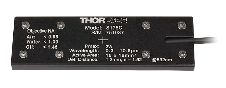
Click to Enlarge
S175Cの筐体の背面には、センサの仕様とビームをセンサの中央に入射させるためのターゲットが刻印されています。
- 波長範囲:300 nm~10.6 μm
- 100 µW~2 Wの光パワーを測定可能
- 顕微鏡の試料面で光パワーを計測できる設計
- 検出部18 mm x 18 mmのサーマルセンサ
- 標準的な顕微鏡スライドと同じ設置面積:76.0 mm x 25.2mm
- コネクタに以下の情報を保存
- センサーデータ
- NISTおよびPTBトレーサブルな校正データ
- 詳細はこちらをご覧ください。
顕微鏡用スライド型サーマルパワーセンサーヘッドS175Cを用いて、顕微鏡システム内の試料面における光パワーを測定できます。こちらのサーマルセンサは、100 µW~2 Wの光パワーで300 nm~10.6 µmの波長を検出できます。76.0 mm x 25.2 mmのセンサーヘッドは、標準の顕微鏡用スライドと同じ設置面積で、多くの標準的な正立および倒立顕微鏡にお使いいただけます。
18 mm x 18 mmの検出部は密封された筐体に収納されており、その上にはガラスカバーが付いています。液浸材(水、グリセロール、油)は、ガラスカバープレートの上につけてください。
右の写真のようにセンサ筐体の背面には、ビームのアライメントと集光を補助するためのターゲットがレーザ刻印されています。標準的な顕微鏡では、このターゲットを用いてビームをアライメントした後、センサーヘッドを反転させて対物レンズに向ければパワーの測定を行うことができます。倒立顕微鏡では、透過照明をオンにしてディテクタ筐体のターゲットとビームを合わせます。これにより、対物レンズの正面中央にセンサがきます。
センサの仕様とNISTおよびPTBトレーサブルな校正データは、センサーコネクタの非揮発性メモリに保存されており、当社の最新世代のパワーメータで読み出すことができます。精度と性能を維持するために年に1度の再校正をお勧めします。当社では、再校正サービスをご提供しております。詳細については当社までお問い合わせください。
仕様の詳細は「仕様」タブをご覧ください。当社では、低パワーで高分解能な測定が可能なフォトダイオードセンサ付き顕微鏡用スライドセンサーヘッドもご用意しております。詳しい製品説明はこちらからご覧いただけます。
| Item #a | S401C | S405C |
|---|---|---|
| Sensor Image (Click the Image to Enlarge) | 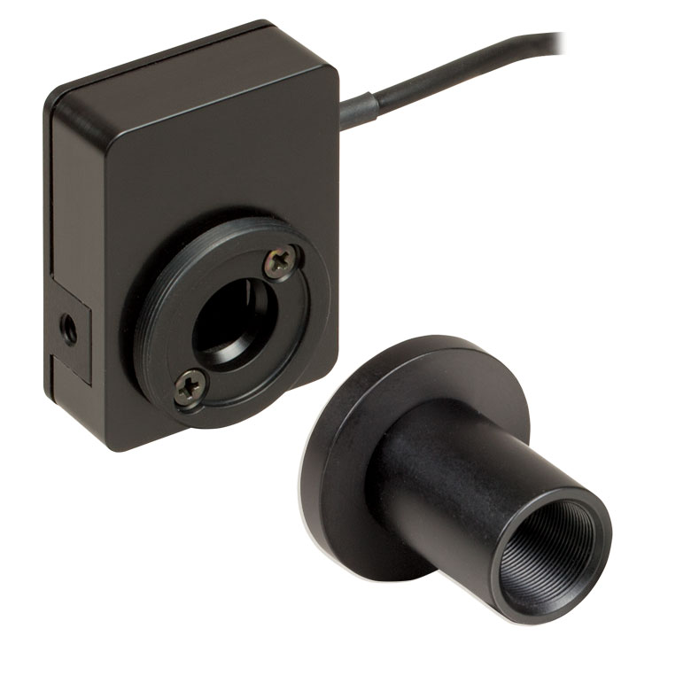 | 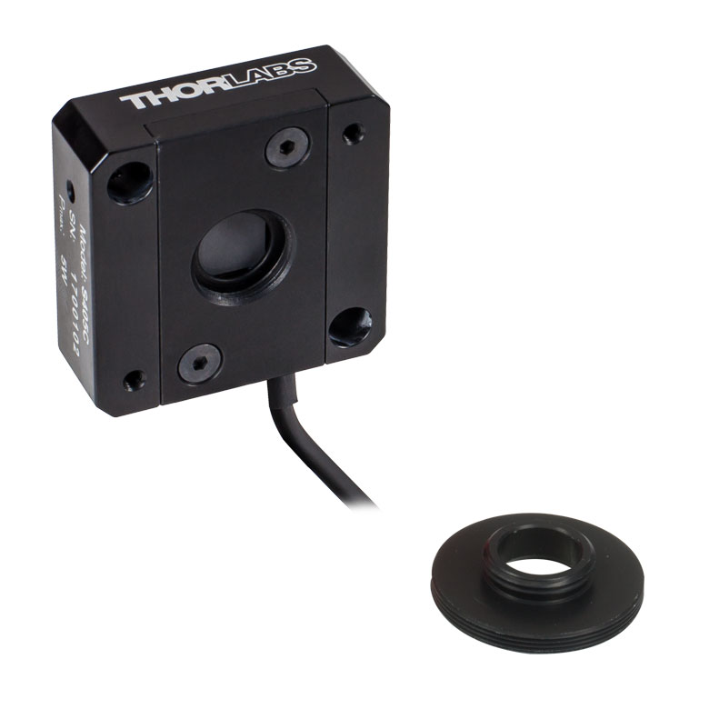 |
| Wavelength Range | 190 nm - 20 µm | 190 nm - 20 µm |
| Optical Power Range | 10 µW - 1 W (3 Wb) | 100 µW - 5 W |
| Input Aperture Size | Ø10 mm | Ø10 mm |
| Active Detector Area | 10 mm x 10 mm | 10 mm x 10 mm |
| Max Optical Power Density | 500 W/cm² (Avg.) | 1.5 kW/cm² (Avg.) |
| Detector Type | Thermal Surface Absorber (Thermopile) with Background Compensation | Thermal Surface Absorber (Thermopile) |
| Linearity | ±0.5% | ±0.5% |
| Resolutionc | 1 µW | 5 µW |
| Measurement Uncertaintyd | ±3% @ 1064 nm ±5% @ 190 nm - 10.6 µm | ±3% @ 1064 nm ±5% @ 250 nm - 17 µm |
| Response Timee | 1.1 s | 1.1 s |
| Cooling | Convection (Passive) | |
| Housing Dimensions (Without Adapter) | (1.30" x 1.69" x 0.59") | 40.6 mm x 40.6 mm x 16.0 mm (1.60" x 1.60" x 0.63") |
| Temperature Sensor (In Sensor Head) | NTC Thermistor | NTC Thermistor |
| Cable Length | 1.5 m | |
| Post Mounting | Universal 8-32 / M4 Taps (Post Not Included) | Universal 8-32 / M4 Taps (Post Not Included) |
| 30 mm Cage Mounting | - | Two 4-40 Tapped Holes & Two Ø6 mm Through Holes |
| Aperture Threads | - | Internal SM05 |
| Accessories | Externally SM1-Threaded Adapter Light Shield with Internal SM05 Threading | Externally SM1-Threaded Adapter |
| Compatible Consoles | PM400, PM100D, PM100A, and PM5020 | |
| Compatible Interfaces | PM101, PM101A, PM101R, PM101U, PM102, PM102A, PM102U, and PM100USB | |
- 1 μWまたは5 μWの高分解能
- S401CとS405Cにはセンサーヘッドの温度をモニタするサーミスタ付き
- S401C: バックグラウンド補正により低ドリフトで測定
- S405C: 最大1.5 kW/cm²の平均パワー密度に対応
- 詳細は、こちらをご覧ください。
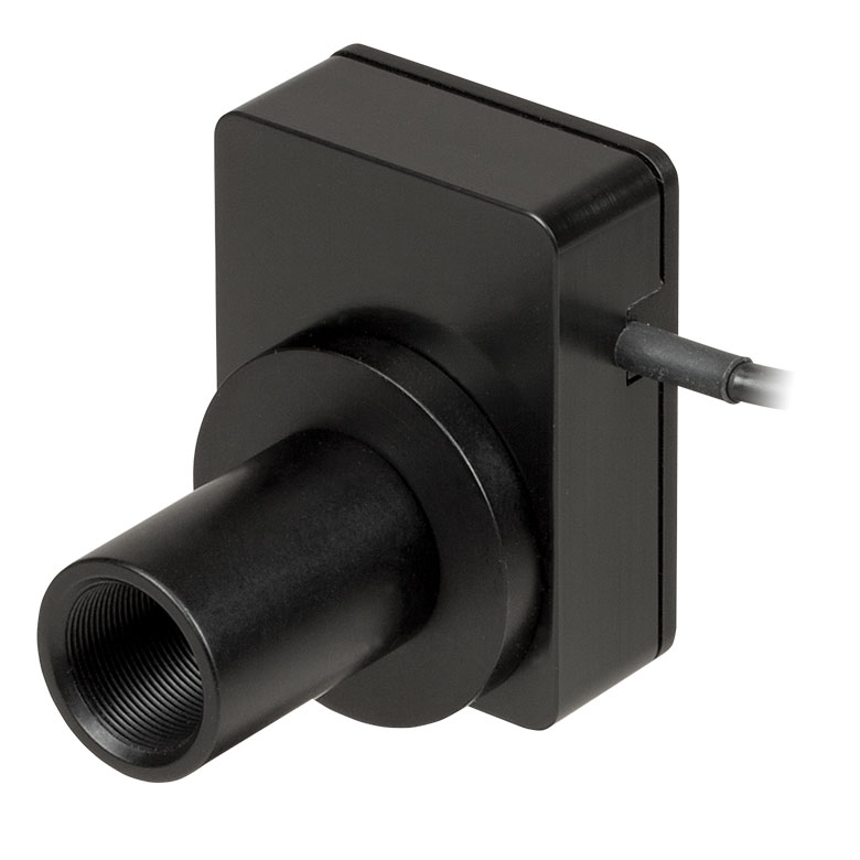
Click to Enlarge
付属の遮光体を取り付けたサーマルセンサS401C
当社では低パワーの光源を高分解能で測定するために設計された広帯域サーマルパワーセンサを3種類ご用意しております。いずれのサーマルセンサの広帯域コーティングも、下のグラフのように広い波長域において平坦なスペクトル応答特性を示します。
Ø10 mmの開口寸法により、スポットサイズの大きいレーザ光源のアライメントや測定が容易です。当社のレンズチューブシステムやSM1ネジ付きファイバーアダプタへの接続用に、各センサにはSM1外ネジが付いているか、あるいはSM1外ネジ付きアダプタが付属しています。
S401Cは、アクティブ型のサーマルバックグラウンド補正により低ドリフトで光パワー測定を行います。これは同様のセンサ回路を2つ使用することで実現しています。1つのセンサ回路はすべてのサーマルパワーセンサが使用するものと同じタイプで、光吸収体からヒートシンクへの熱流量を測定します。もう1つのセンサ回路は周囲温度をモニタします。2つのセンサ回路の測定値が差し引かれるので、レーザーパワー測定におけるサーマルドリフトの影響は最小限に抑えられます (外部からの熱的擾乱がどのようにサーマルパワーセンサの読取値に影響するかについての詳細は、製品ページの「動作」タブをご覧ください)。こちらのサーマルセンサに使用している広帯域コーティングは、0.19~20 µm(グラフ参照)の波長域で高い吸収を示します。そのため、中赤外域(MIR)の量子カスケードレーザ(QCL)のアライメントや測定にお使いいただけます。付属のSM05内ネジ付き遮光体は、上または下の写真でご覧いただけます。
S405CにはSM05内ネジがあり、SM05レンズチューブに直接取り付けられます。また、当社の30 mmケージシステムにも直接取り付けられます。
当社ではこれらのセンサに対して再校正サービスをご提供しております。詳細については当社までお問い合わせください。

Click to Enlarge
S415C、S425C、S245C-Lの吸収曲線はS405と同じです(すべて下記参照)。
| Item #a | S415C | S425C |
|---|---|---|
| Sensor Image (Click Image to Enlarge) | 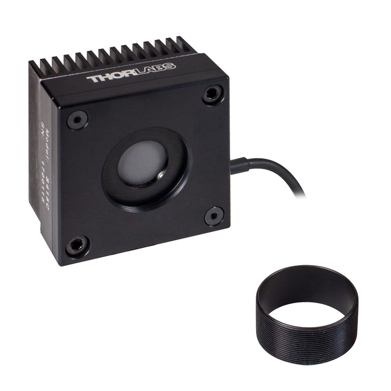 |  |
| Wavelength Range | 190 nm - 20 µm | 190 nm - 20 µm |
| Optical Power Range | 2 mW - 10 W (20 Wb) | 2 mW - 10 W (20 Wb) |
| Input Aperture Size | Ø15 mm | Ø25.4 mm |
| Active Detector Area | Ø15 mm | Ø27 mm |
| Max Optical Power Density | 1.5 kW/cm² (Avg.) | 1.5 kW/cm² (Avg.) |
| Detector Type | Thermal Surface Absorber (Thermopile) | |
| Linearity | ±0.5% | ±0.5% |
| Resolutionc | 100 µW | 100 µW |
| Measurement Uncertaintyd | ±3% @ 1064 nm ±5% @ 250 nm - 17 µm | ±3% @ 1064 nm ±5% @ 250 nm - 17 µm |
| Response Timee | 0.6 s | 0.6 s |
| Cooling | Convection (Passive) | |
| Housing Dimensions (Without Adapter) | (2.00" x 2.00" x 1.38") | (2.00" x 2.00" x 1.38") |
| Temperature Sensor (In Sensor Head) | NTC Thermistor | |
| Cable Length | 1.5 m | |
| Post Mounting | Universal 8-32 / M4 Taps (Post Not Included) | Universal 8-32 / M4 Taps (Post Not Included) |
| 30 mm Cage Mounting | - | - |
| Aperture Threads | Internal SM1 | Internal SM1 |
| Removable Heatsink | Yes | Yes |
| Accessories | Externally SM1-Threaded Adapter | Externally SM1-Threaded Adapter |
| Compatible Consoles | PM400, PM100D, PM100A, and PM5020 | |
| Compatible Interfaces | PM101, PM101A, PM101R, PM101U, PM102, PM102A, PM102U, and PM100USB | |
- 光パワーの分解能は100 µW
- センサーヘッドの温度をモニタするサーミスタ付き
- 取外し可能なヒートシンク
- 詳細はこちらをご覧ください
こちらのサーマルパワーセンサは、低~中程度の広いパワー範囲の測定用に設計されています。全ての製品には入射開口部と同心のSM1外ネジ付きアダプタが付属します。このアダプタはØ25 mm~Ø25.4 mm(Ø1インチ)レンズチューブを取り付ける際に便利です(下記参照)。S415CおよびS425Cの開口にはSM1内ネジが付いています。
このセンサの応答時間は0.6秒以下です。ヒートシンクは取り外しが可能なため、カスタム仕様のセットアップに組み込んだり、ヒートシンクを取り外して水冷式やファン空冷式のものに取り換えるなどのご要望にも対応します。ヒートシンクを交換する場合には、交換後のヒートシンクが用途に適した放熱を行えるようにしてください。
当社ではこれらのセンサに対して再校正サービスをご提供しております。詳細については当社までお問い合わせください。
Click to Enlarge
低~中程度の広いパワー範囲に対応したサーマルパワーセンサの吸収曲線。
Click to Enlarge
低~中程度の広いパワー範囲に対応したサーマルパワーセンサの吸収曲線。
- センサーヘッドの温度をモニタするサーミスタ付き
- S322Cには当社の30 mmケージシステムに対応した#4-40タップ穴付き
- S350Cにはスポットサイズの大きなエキシマレーザなどに適したØ40 mmの開口付き
- S425C-Lには取外し可能なヒートシンク
- S322Cはファン空冷式で光パワーの測定範囲は最大200 W
- 詳細は、こちらをご参照ください。
こちらのサーマルパワーセンサは、低~中程度の広いパワー範囲の測定用に設計されています。 S350Cを除くすべての製品には、入射開口部と同心のSM1外ネジ付きアダプタが付属します。これによって、センサにはファイバーアダプタ(下記参照)が使用可能です。また、既存のØ25 mm~Ø25.4 mm(Ø1インチ)レンズチューブに組み込むこともできます。S425C-Lの開口にはSM1内ネジが付いています。
S425C-Lのセンサの応答時間は0.6秒以下です。ヒートシンクは取り外しが可能なため、カスタム仕様のセットアップに組み込んだり、ヒートシンクを取り外して水冷式やファン空冷式のものに取り換えるなどのご要望にも対応します。ヒートシンクを交換する場合には、交換後のヒートシンクが用途に適した放熱を行えるようにしてください。
当社ではこれらのセンサに対して再校正サービスをご提供しております。詳細については当社までお問い合わせください。
| Item #a | S350C | S425C-L | S322C |
|---|---|---|---|
| Sensor Image (Click Image to Enlarge) | 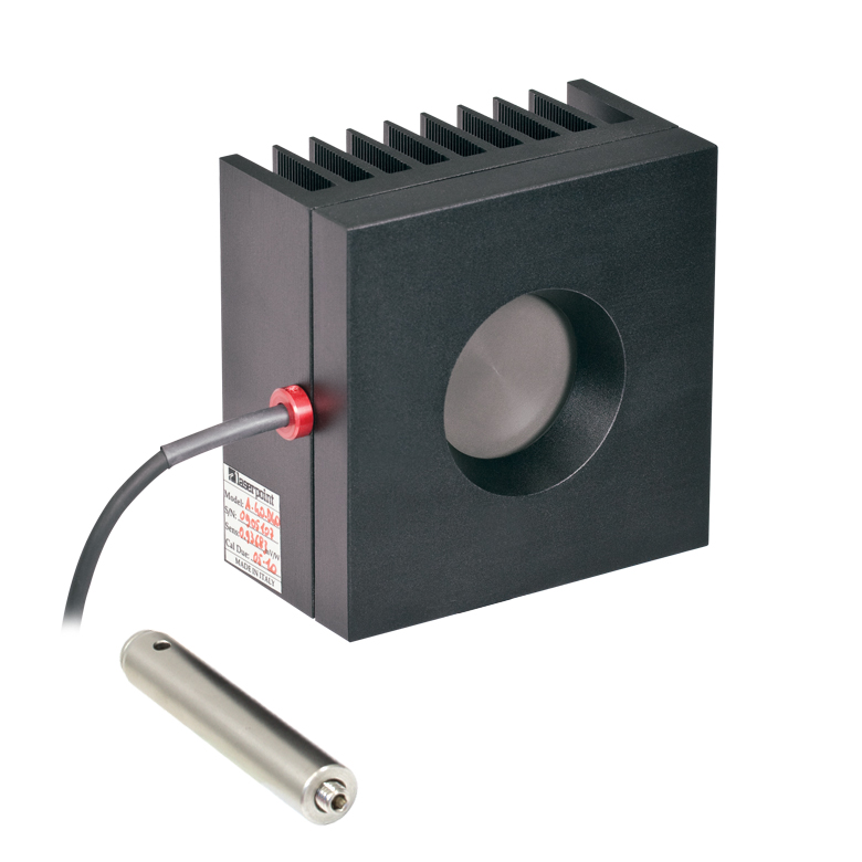 |  |  |
| Wavelength Range | 190 nm- 1.1 µm, 10.6 µm | 190 nm - 20 µm | 250 nm - 11 µm |
| Optical Power Range | 10 mW - 40 W (60 Wb) | 2 mW - 50 W (75 Wb) | 100 mW - 200 W (250 Wb) |
| Input Aperture Size | Ø40 mm | Ø25.4 mm | Ø25 mm |
| Active Detector Area | Ø40 mm | Ø27 mm | Ø25 mm |
| Max Optical Power Density | 2 kW/cm² (Avg.) | 1.5 kW/cm² (Avg.) | 4 kW/cm² (Avg., CO2) |
| Detector Type | Thermal Surface Absorber (Thermopile) | ||
| Linearity | ±1% | ±0.5% | ±1% |
| Resolutionc | 1 mW | 100 µW | 5 mW |
| Measurement Uncertaintyd | ±3% @ 1064 nm ±5% @ 190 nm - 1100 nm, 10.6 µm | ±3% @ 1064 nm ±5% @ 250 nm - 17 µm | ±3% @ 1064 nm ±5% @ 266 nm - 1064 nm |
| Response Timee | 9 s (1 s from 0 to 90%) | 0.6 s | 5 s (1 s from 0 to 90%) |
| Cooling | Convection (Passive) | Forced Air with Fanf | |
| Housing Dimensions (Without Adapter, if Applicable) | 100 mm x 100 mm x 54.2 mm (3.94" x 3.94" x 2.13") | 100.0 mm x 100.0 mm x 58.0 mm (3.94" x 3.94" x 2.28") | 100 mm x 100 mm x 86.7 mm (3.94" x 3.94" x 3.41") |
| Temperature Sensor (In Sensor Head) | NTC Thermistor | ||
| Cable Length | 1.5 m | ||
| Post Mounting | M6 Threaded Taps, Includes Ø1/2" Post, 75 mm Long | Universal 8-32 / M4 Taps (Post Not Included) | M6 Threaded Taps, Includes Ø1/2" Post, 75 mm Long |
| 30 mm Cage Mounting | - | - | Four 4-40 Tapped Holes |
| Aperture Threads | - | Internal SM1 | - |
| Removable Heatsink | - | Yes | - |
| Accessories | - | Externally SM1-Threaded Adapter | Externally SM1-Threaded Adapter |
| Compatible Consoles | PM400, PM100D, PM100A, and PM5020 | ||
| Compatible Interfaces | PM101, PM101A, PM101R, PM101U, PM102, PM102A, PM102U, and PM100USB | ||
| Item #a | S370C | S470C |
|---|---|---|
| Sensor Image (Click the Image to Enlarge) | 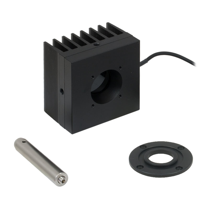 | 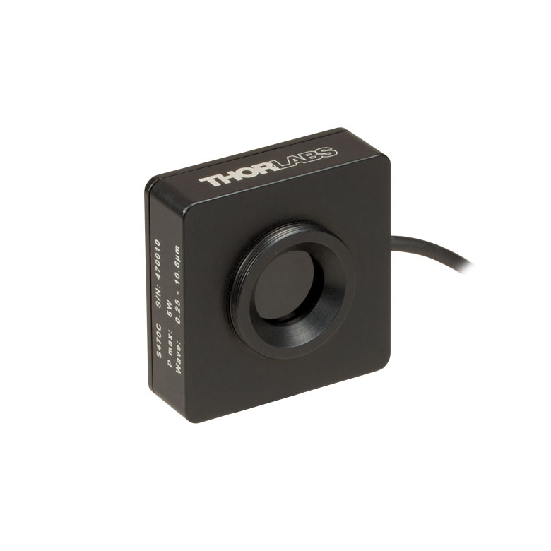 |
| Wavelength Range | 400 nm - 5.2 µm | 250 nm - 10.6 µm |
| Optical Power Range | 10 mW - 10 W (15 Wb) | 100 µW - 5 W (Pulsed and CW) |
| Input Aperture Size | Ø25 mm | Ø15 mm |
| Active Detector Area | Ø25 mm | Ø16 mm |
| Max Optical Power Density | 35 W/cm² (Avg.); 100 GW/cm² (Peak) | |
| Detector Type | Thermal Volume Absorber (Thermopile) | |
| Linearity | ±1% | ±0.5% |
| Resolutionc | 250 µW | 10 µW |
| Measurement Uncertaintyd | ±3% @ 1064 nm ±5% @ 400 nm - 1064 nm | ±3% @ 1064 nm ±5% @ 250 nm - 10.6 µm |
| Response Timee | 45 s (3 s from 0 to 90%) | 6.5 s (<2 s from 0 to 90%) |
| Cooling | Convection (Passive) | |
| Housing Dimensions (Without Adapter, if Applicable) | (2.95" x 2.95" x 2.02") | (1.77" x 1.77" x 0.71") |
| Temperature Sensor (In Sensor Head) | N/A | N/A |
| Cable Length | 1.5 m | |
| Post Mounting | M6 Threaded Taps, Includes Ø1/2" Post, 75 mm Long | Universal 8-32 / M4 Tap (Post Not Included) |
| 30 mm Cage Mounting | Four 4-40 Tapped Holes | - |
| Aperture Threads | - | External SM1 |
| Accessories | - | |
| Compatible Consoles | PM400, PM100D, PM100A, and PM5020 | |
| Compatible Interfaces | PM101, PM101A, PM101R, PM101U, PM102, PM102A, PM102U, and PM100USB | |
- Nd:YAGレーザの光パワー測定用
- ピークパワーの大きなパルスレーザに適した製品
- S370C: スポットサイズの大きなビームに対応したØ25 mmの開口
- S470C: 平均パワーが小さく、ピークパワーが大きなパルスレーザに対して高感度
- 詳細は、こちらをご参照ください。
サーマルセンサS370CならびにS470Cは、高エネルギーの短パルスレーザ用に設計されています。 すべてのユニットは自由空間光を測定するためにポストに取り付けることができ、またセンサのコネクタ部にはNISTトレーサブルなデータが保存されています。
これらのサーマルパワーセンサは体積吸収体を使用している点がユニークな特長です。他のサーマルパワーセンサでは表面吸収体が使用されています。体積吸収体はSchott社製ガラスフィルタでできています。入射パルスは吸収され、熱は体積全体に分散されます。このため、表面吸収体の吸収コーティングを損傷するようなパルスでも、体積吸収体ではより安全に測定することができます。
S370Cの開口部はØ25 mmと大きく、スポットサイズが大きいビームの測定に適しており、平均パワー10 mW~10 W(CW)に対応しています。
S370Cと比較してS470Cは応答が速くなっていますが、これはガラス吸収体の体積が小さく、またその他の設計パラメータも速度を上げるために最適化されているためです。その結果、光パワーの測定範囲も異なり、100 µWの低いパワーまで測定できます。S470Cの開口部はØ15 mmと小さく、また最大平均パワーも5 Wと小さくなっています。分解能は10 µWで、S370Cの250 µWと比較して優れています。
当社ではこれらのセンサに対して再校正サービスをご提供しております。詳細については当社までお問い合わせください。
Click to Enlarge
この吸収曲線はセンサの動作範囲よりも広い波長範囲を表示しています。各センサの動作波長範囲については表をご覧ください。
| Item #a | S440C | S442C |
|---|---|---|
| Sensor Image (Click the Image to Enlarge) | 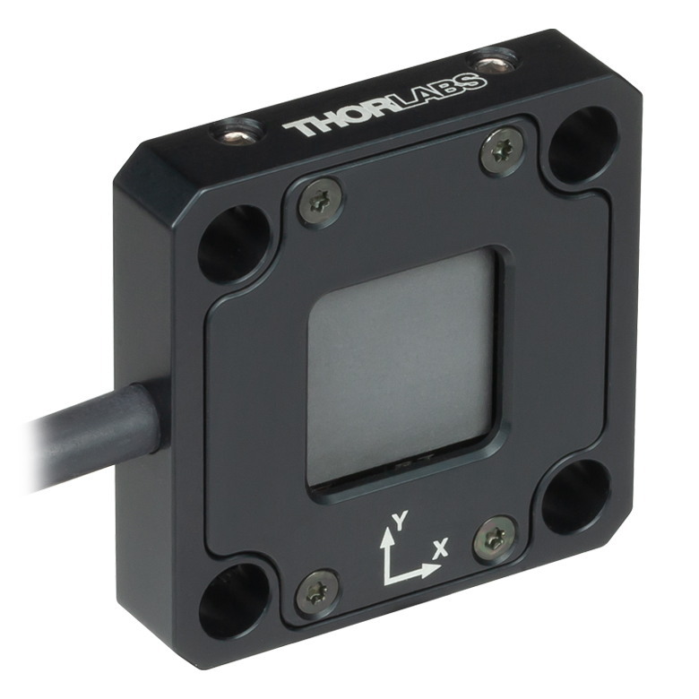 | 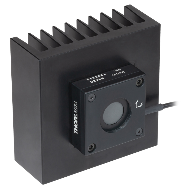 |
| Wavelength Range | 190 nm - 20 µm | |
| Optical Power Range | 0.5 mW - 5 W | 10 mW - 50 W |
| Input Aperture Size | 17 mm x 17 mm | Ø17.5 mm |
| Max Optical Power Density | 1.5 kW/cm2 | |
| Detector Type | Four Thermopiles in Quadrant Configuration | |
| Linearity | ±1% | |
| Resolutionb | 50 µW | 1 mW |
| Measurement Uncertaintyc | ±5% at 1064 nm; ±7% for 250 nm - 17 µm | |
| Position Resolution | 5 µm | 10 µm |
| Position Accuracyd | 50 µm (Ø1 mm Circle) 200 µm (Ø6 mm Circle) | 100 µm (Ø1 mm Circle) 300 µm (Ø6 mm Circle) |
| Position Repeatabilityd | 15 µm (Ø1 mm Circle) 100 µm (Ø6 mm Circle) | 25 µm (Ø1 mm Circle) 150 µm (Ø6 mm Circle) |
| Response Timee | < 1.1 s | < 0.6 s |
| Cooling | Convection (Passive) | |
| Housing Dimensions (Without Adapter) | 40.6 mm x 40.6 mm x 8.9 mm (1.60" x 1.60" x 0.35") | 100.0 m x 100.0 mm x 57.8 mm (3.94" x 3.94" x 2.28") |
| Temperature Sensor (In Sensor Head) | NTC Thermistor | |
| Cable Length | 1.5 m | |
| Post Mounting | One 8-32 / M4 Universal Tap | Two 8-32 / M4 Universal Taps |
| 30 mm Cage Mounting | Four Ø6 mm Through Holes | - |
| Aperture Threads | - | Internal SM1 (1.035"-40) |
| Accessories | - | Externally SM1-Threaded Adapter |
| Compatible Consoles | PM400 and PM5020 | |
| Compatible Interfaces | PM102, PM102A, and PM102U | |
- 4分割位置検出器
- S440C:高感度型、30 mmケージシステムに対応
- S442C:高パワー対応型、ヒートシンクが付属
- 詳細は、こちらをご参照ください。
位置&パワーセンサS440CおよびS442C は、サーモパイルセンサ素子を用いてビームの位置とパワーを高分解能で測定します。検出器の受光面は、四角形の4象限の各位置に配置された4つのサーモパイルセンサから構成されています。各象限のセンサは機械的に結合されていますが、電気的には絶縁されています。したがって、熱は検出部全体を自由に流れますが、各象限からの電気信号はその象限のサーモパイルだけからの応答を表しています。ビームの位置(X、Y)は、4つの各象限からの信号強度を比較することで決定されます。
ディテクタS440Cは、0.5 mW~5 Wのパワーを高感度に検出するように最適化されています。筐体には30 mmケージシステム取付け用のØ6 mm貫通穴が4つと、ポスト取付け用のM4/#8-32タップ穴(ミリ・インチ規格共用)が付いています。ディテクタS442Cは、10 mWから最大50 Wの高パワーに対応します。筐体には放熱性に優れたヒートシンクが付いており、また、ポスト取付け用のM4/#8-32タップ穴(ミリ・インチ規格共用)が2つ付いています。
どちらのディテクタにも、NIST/PTBトレーサブルの校正データが記録されているCシリーズコネクタが付いています。 これらのセンサはパワーメーターコンソールPM400、PM5020、またはPM102シリーズパワーメーターインターフェイスを使用して制御できます。システムのディスプレイは、位置の経時変化の視覚的なトレース、XおよびY位置の経時変化のグラフ、測定結果の統計値の表、入射パワーの数値などを表示するように構成することができます。詳細については製品ページやPM400マニュアルをご覧ください。
こちらの製品の再校正サービスにつきましては当社までお問い合わせください。
Click to Enlarge
生データはこちらからダウンロードできます。
このグラフに示すデータの波長範囲は、試験に使用したディテクタによって制限されています。サーマル位置検出器は、長波長側は20 µmまで動作可能です。
| Item #a | ES111C | ES120C | ES145C |
|---|---|---|---|
| Sensor Image (Click the Image to Enlarge) | 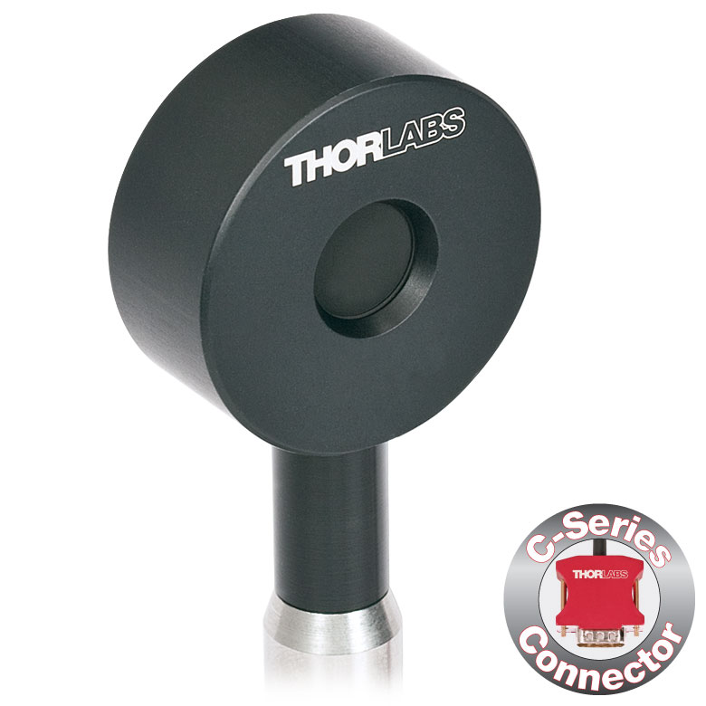 | 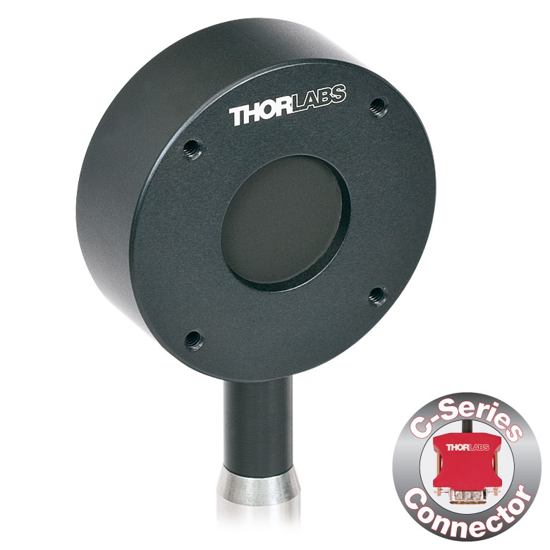 | 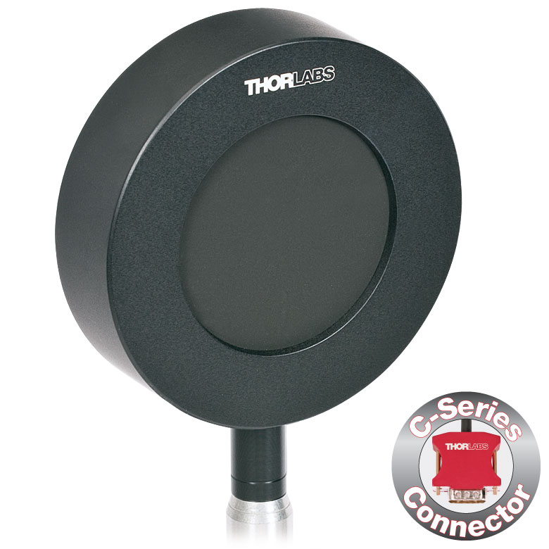 |
| Input Aperture Size | Ø11 mm | Ø20 mm | Ø45 mm |
| Wavelength Range | 0.185 - 25 µm | ||
| Energy Range | 10 µJ - 150 mJ | 100 µJ - 500 mJ | 500 µJ - 2 J |
| Max Repetition Rateb | 40 Hz | 30 Hz | 30 Hz |
| Max Power Density (Pulse Width) | 8 MW/cm2 (10 ns Pulse) | ||
| Max Pulse Energy Density (Pulse Width) | 0.15 J/cm2 (1 µs Pulse) | ||
| Coating (Click for Plot) | Black Broadband | ||
| Resolution | 100 nJ | 1 µJ | 1 µJ |
| Linearity | ±1% | ||
| Measurement Uncertainty | ±5% @ 190 nm - 25 µm | ±5% @ 185 nm - 25 µm | ±5% @ 185 nm - 25 µm |
| Housing Dimensions | Ø36 mm x 16 mm | Ø50 mm x 18 mm | Ø75 mm x 21 mm |
| Active Detector Area | 95.0 mm2 | 314.2 mm2 | 1590.4 mm2 |
| Cable Length | 1.5 m (60") | ||
| Post Mounting | 8-32 Mounting Thread, 8-32 and M4 Insulating Adapters Included | ||
| Cage Mounting | N/A | Four 4-40 Threaded Holes for 30 mm Cage Systems | N/A |
| Compatible Consoles | PM400, PM100D, and PM5020 | ||
| Compatible Interfaces | PM103, PM103A, PM103E, PM103U, and PM100USB | ||
- 一般的な光パルス測定用
- 広い波長範囲で平坦な波長応答性を実現する黒色の広帯域コーテイング
- 検出部:Ø11 mm、Ø20 mm、Ø45 mm
- オシロスコープ用のBNCコネクタ
- 各センサの付属品
- 当社のコンソールと使用可能なCシリーズのコネクターアダプタ(下表または「コンソールセレクション」タブ参照)
- 電気的に絶縁されたポスト用アダプタ(ミリ規格品とインチ規格品それぞれ1つずつ)
- 詳細についてはこちらの製品紹介ページをご覧ください。
標準焦電センサES1xxCは、コヒーレント光源およびインコヒーレント光源からのパルス測定用に設計されています。焦電センサは、光パルスのエネルギを電圧パルスに変換する測定原理であるため、CW光源の測定には適しません。黒色広帯域コーティングの平坦な吸収プロファイルにより(下表参照)、低パワーで波長に無依存なエネルギ測定に適します。検出部がØ11 mm、Ø20 mm、Ø45 mmと大きいため、アライメントが容易です。また、これらのセンサは、BNCコネクタを介して1 MΩ入力抵抗のオシロスコープに直接接続することができます。高い繰返しレートのパルスをオシロスコープで測定する場合、負荷抵抗を下げることで対応が可能です。各エネルギーセンサには、NISTおよびPTBにトレーサブルの校正データが付いたBNC-Cシリーズ変換アダプタも含まれます。
当社では、エネルギーセンサの再校正サービスをご提供しています。詳細については当社までお問い合わせください。
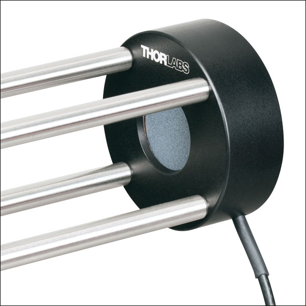
Click to Enlarge
30 mmケージシステムに取り付けたセンサES220C
- 最大15 Jまでの高エネルギ光パルスの測定が可能
- 高エネルギ密度レーザ(最大0.45 J/cm2)用に高い損傷閾値のセラミックコーティング
- 検出部: Ø20 mmまたはØ45 mm
- オシロスコープ用のBNCコネクタ
- 各センサの付属品
- 当社のコンソールと使用可能なCシリーズのコネクターアダプタ(下表または「コンソールセレクション」タブ参照)
- 電気的に絶縁されたポスト用アダプタ(ミリ規格品とインチ規格品それぞれ1つずつ)
- 詳細はこちらの製品紹介ページをご参照ください。
高エネルギ焦電センサES2xxCは、コヒーレント光源およびインコヒーレント光源からのパルス測定用に設計されています。焦電センサは、光パルスのエネルギを電圧パルスに変換する測定原理であるため、CW光源の測定には適しません。セラミックコーティングが使用されているため、センサES220Cでは3 Jまで、ES245Cでは15 Jまでの高エネルギ測定が可能です。検出部がØ20 mmまたはØ45 mmと大きいため、アライメントが容易です。また、これらのセンサは、BNCコネクタを介して1 MΩ入力抵抗のオシロスコープに直接接続することができます。高い繰返しレートのパルスをオシロスコープで測定する場合、負荷抵抗を下げることで対応が可能です。各エネルギーセンサには、NISTおよびPTBにトレーサブルの校正データが付いたBNC-Cシリーズ変換アダプタも含まれます。
当社では、エネルギーセンサの再校正サービスをご提供しています。詳細については当社までお問い合わせください。
| Item #a | ES220C | ES245C |
|---|---|---|
| Sensor Image (Click the Image to Enlarge) | 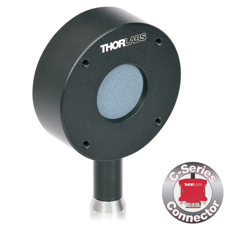 | 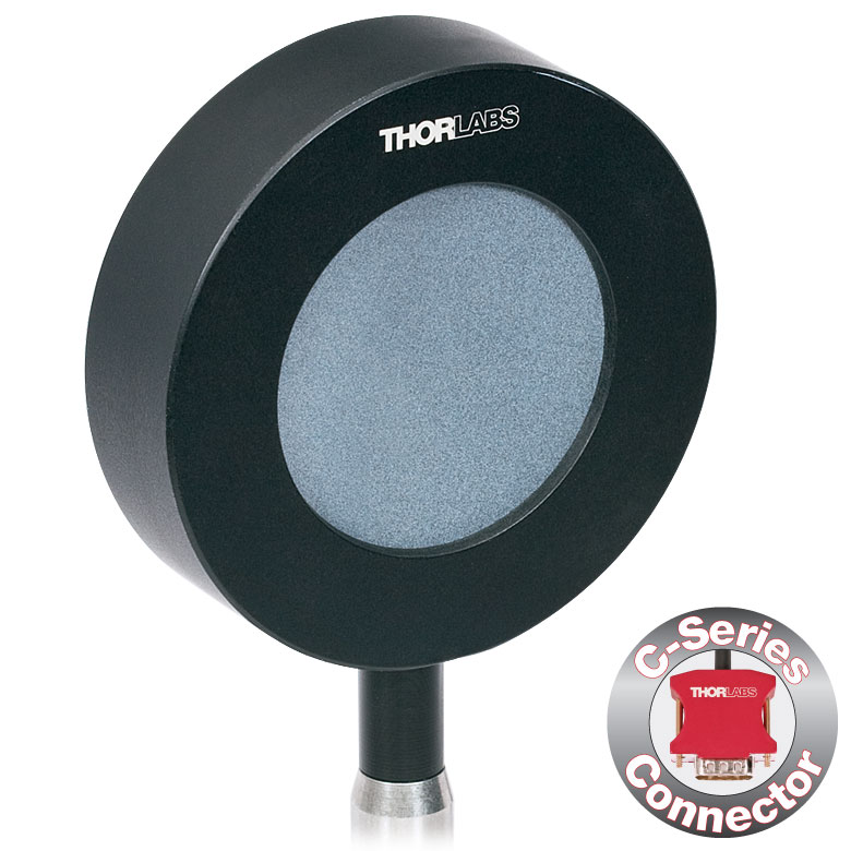 |
| Input Aperture Size | Ø20 mm | Ø45 mm |
| Wavelength Range | 0.185 - 25 µm | |
| Energy Range | 500 µJ - 3 J | 1 mJ - 15 J |
| Max Repetition Rateb | 30 Hz | 30 Hz |
| Max Power Density (Pulse Width) | 65 MW/cm2 (7 ns Pulse @ 355 nm) | |
| Max Pulse Energy Density (Pulse Width) | 0.45 J/cm2 (7 ns Pulse @ 355 nm) | |
| Coating (Click for Plot) | Ceramic | |
| Resolution | 25 µJ | 50 µJ |
| Linearity | ±1% | |
| Measurement Uncertainty | ±5% @ 0.185 - 25 µm | |
| Housing Dimensions | Ø50 mm x 18 mm | Ø75 mm x 21 mm |
| Active Detector Area | 314.2 mm2 | 1590.4 mm2 |
| Cable Length | 1.5 m (60") | |
| Post Mounting | 8-32 Mounting Thread, 8-32 and M4 Insulating Adapters Included | |
| Cage Mounting | Four 4-40 Threaded Holes for 30 mm Cage Systems | N/A |
| Compatible Consoles | PM400, PM100D, and PM5020 | |
| Compatible Interfaces | PM103, PM103A, PM103E, PM103U, and PM100USB | |
- 最大10 kHzまでの繰返し周波数の測定が可能
- 2種類のコーティング:
- 平坦な応答性を有する黒色広帯域コーティング(185 nm~25 µm)
- 最大10 kHzまでの繰返し周波数を検出可能な金属コーティング
- 検出部:Ø8 mmまたはØ12 mm
- オシロスコープ用のBNCコネクタ
- 当社のコンソールと使用可能なCシリーズのコネクターアダプタ(下表または「コンソールセレクション」タブ参照)が付属
- 詳細はこちらの製品紹介ページをご参照ください。
こちらの高速焦電センサは、繰返し周波数が最大10 kHzまでのコヒーレント光源およびインコヒーレント光源からのパルス測定用に設計されています。焦電センサは、光パルスのエネルギーを電圧パルスに変換する測定原理であるため、CW光源の測定には適しません。センサES3xxC は、黒色広帯域コーティングが施されており、185 nm~25 µmの広帯域で平坦な応答性を有します。また、センサのサイズによりますが、最大1 kHzまでの繰返し周波数の測定が可能です。金属コーティング付きのセンサE4xxCは、185 nm~2.5 µmのより狭い波長範囲にわたり、最大10 kHzまでの繰返し周波数を検出できます(センサのサイズによります)。検出部はØ8 mmまたはØ12 mmで、各入射開口部には当社のSM1ネジ付きレンズチューブに対応するSM1外ネジが付いています。これらのエネルギーセンサにはBNCコネクタが付いており、入力負荷抵抗1 MΩのオシロスコープに接続可能です。ただし、これ以外の負荷抵抗で使用すると速度が低下する可能性があります。各センサには、NISTおよびPTBにトレーサブルの校正データが付いたBNC-Cシリーズ変換アダプタも含まれます。
当社では、エネルギーセンサの再校正サービスをご提供しています。詳細については当社までお問い合わせください。
| Item #a | ES308C | ES312C | ES408C | ES412C |
|---|---|---|---|---|
| Sensor Image (Click the Image to Enlarge) | 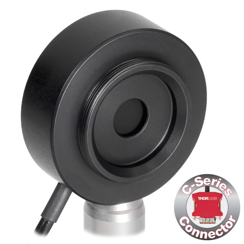 | 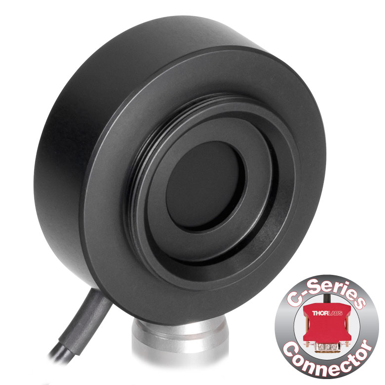 | 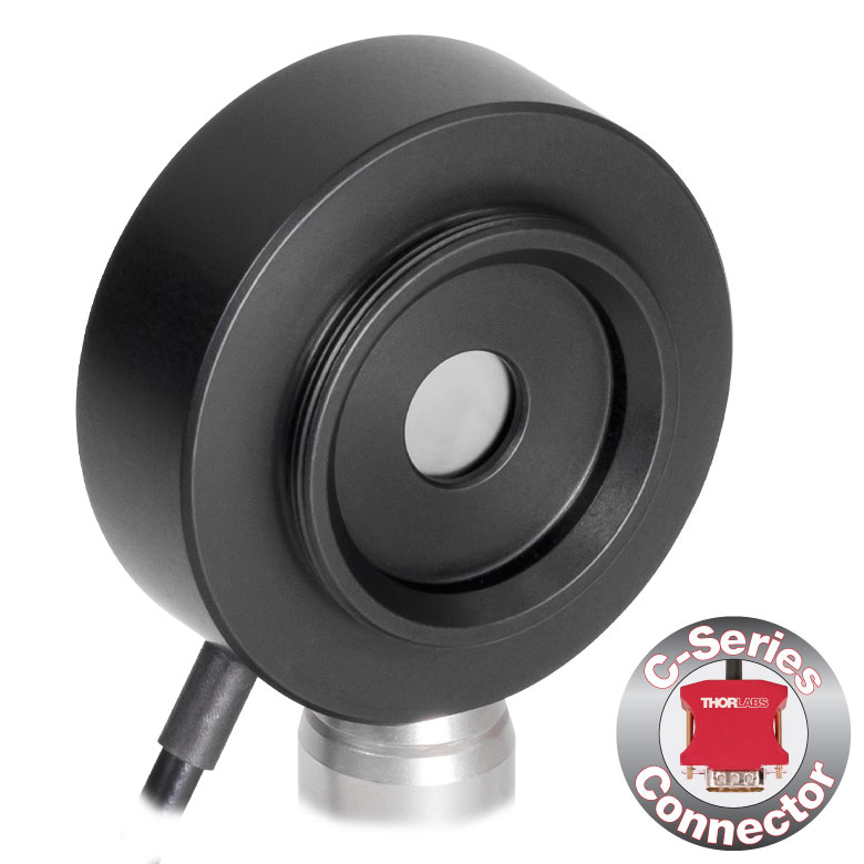 | 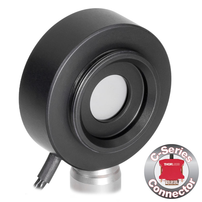 |
| Input Aperture Size | Ø8 mm | Ø12 mm | Ø8 mm | Ø12 mm |
| Wavelength Range | 0.185 - 25 µm | 0.185 - 2.5 µm | ||
| Energy Range | 500 µJ - 1 J | 100 µJ - 1 J | 100 µJ - 1 J | 50 µJ - 500 mJ |
| Max Repetition Rateb | 1 kHz | 250 Hz | 10 kHz | 2 kHz |
| Max Power Density (Pulse Width) | 8 MW/cm2 (10 ns Pulse) | 5 MW/cm2 (10 ns Pulse) | ||
| Max Pulse Energy Density (Pulse Width) | 80 mJ/cm2 (10 ns Pulse) | 50 mJ/cm2 (10 ns Pulse) | ||
| Coating (Click for Plot) | Black Broadband | Metal | ||
| Resolution | 5 µJ | 1 µJ | 1 µJ | 1 µJ |
| Linearity | ±1% | |||
| Measurement Uncertainty | ±5% @ 0.185 - 25 µm | ±5% @ 0.185 - 2.5 µm | ||
| Housing Dimensionsc | Ø38 mm x 15 mm | Ø38 mm x 15 mm | Ø38 mm x 15 mm | Ø38 mm x 15 mm |
| Active Detector Area | 50.3 mm2 | 113.1 mm2 | 50.3 mm2 | 113.1 mm2 |
| Cable Length | 1.5 m (60") | |||
| Post Mounting | 8-32 and M4 Combi Mounting Thread | |||
| Aperture Thread | External SM1 (1.035"-40) Thread Thread Depth: 3.0 mm (0.12") | |||
| Compatible Consoles | PM400, PM100D, and PM5020 | PM5020 | PM400, PM100D, and PM5020 | |
| Compatible Interfaces | PM103, PM103A, PM103E, PM103U, and PM100USB | PM103, PM103A, PM103E, and PM103U | PM103, PM103A, PM103E, PM103U, and PM100USB | |
※パワーセンサ校正について - 当社のパワーセンサ校正は自動で行われており、測定と同時にセンサ内のメモリにある補正データを書き換えます(出力されるデータは校正前の感度と校正後の感度になります)。また、センサ面(NDフィルタ)が汚れ等で正常に感度測定ができないと判断された場合には、フィルタ交換(無償)してから校正される場合がございますので、ご了承ください。この場合は校正前の感度は測定できません。測定と校正を別々に実施する場合には、事前のご連絡が必要です。また、校正のみの場合とは金額および期間が異なりますのでご注意ください。
| Calibration Service Item # | Compatible Sensors |
|---|---|
| CAL-UVPD | S120VC |
| CAL-PD | S116C, S120C, S121C, S170C, S171C, S140C, S142C, S142CL, S150C, S151C, PM16-120, PM16 |
| CAL-UVPD2 | S130VC |
| CAL-PD2 | S130C, PM16-130, PM160 |
| CAL-IRPD | S122C, S144C, S145C, S145CL, S146C, S154C, S155C, PM16-122, PM16-144 |
| CAL-IRPD2 | S132C |
| CAL-MIRPD | S148C, S180C |
Thorlabs offers recalibration services for our photodiode optical power sensors. To ensure accurate measurements, we recommend recalibrating the sensors annually. Recalibration of a single-channel power and/or energy meter console or interface is included with the recalibration of a sensor at no additional cost. If you wish to calibrate one or more sensors with a dual-channel console, each sensor and console calibration service will need to be purchased individually. For more details on these recalibration services, please click the Documents (![]() ) icons below.
) icons below.
Refer to the table to the right for the appropriate calibration service Item # that corresponds to your power sensor.
Requesting a Calibration
Thorlabs provides two options for requesting a calibration:
- Complete the Returns Material Authorization (RMA) form. When completing the RMA form, please enter your name, contact information, the Part #, and the Serial # of each item being returned for calibration; in the Reason for Return field, select "I would like an item to be calibrated." All other fields are optional. Once the form has been submitted, a member of our RMA team will reach out to provide an RMA Number, return instructions, and to verify billing and payment information.
- Select the appropriate sensor calibration Item # below, enter the Part # and Serial # of the sensor that requires recalibration, and then Add to Cart. If you would like a console calibrated with your sensor, repeat this process for Item # CAL-PM1 or CAL-PM2 below, entering the console Item # and Serial #. A member of our RMA team will reach out to coordinate the return of the item(s) for calibration. Note that each console calibration Item # represents the cost of calibrating a console alone; if requesting a single-channel console calibration with a sensor calibration, the appropriate discount will be applied when your request is processed. Should you have other items in your cart, note that the calibration request will be split off from your order for RMA processing.
Please Note: To ensure your item being returned for calibration is routed appropriately once it arrives at our facility, please do not ship it prior to being provided an RMA Number and return instructions by a member of our team.
※パワーセンサ校正について - 当社のパワーセンサ校正は自動で行われており、測定と同時にセンサ内のメモリにある補正データを書き換えます(出力されるデータは校正前の感度と校正後の感度になります)。また、センサ面(NDフィルタ)が汚れ等で正常に感度測定ができないと判断された場合には、フィルタ交換(無償)してから校正される場合がございますので、ご了承ください。この場合は校正前の感度は測定できません。測定と校正を別々に実施する場合には、事前のご連絡が必要です。また、校正のみの場合とは金額および期間が異なりますのでご注意ください。
| Sensor Type | Sensor Item #s |
|---|---|
| Thermal Power | S175C, S302Ca, S305Ca, S310Ca, S314Ca,S322C, S350C, S370C, S401C, S405C, S415C, S425C, S425C-L, S470C, PM160T, PM160T-HP, PM16-401, PM16-405 |
| Pyroelectric Energy | ES111C, ES120C, ES145C, ES220C, ES245C, ES308C, ES312C, ES408C, ES412C |
Thorlabs offers recalibration services for our Thermal Power and Pyroelectric Energy Sensors. To ensure accurate measurements, we recommend recalibrating the sensors annually. Recalibration of a single-channel power and/or energy meter console or interface is included with the recalibration of a sensor at no additional cost. If you wish to calibrate one or more sensors with a dual-channel console, each sensor and console calibration service will need to be purchased individually.
Please note that the CAL-THPY recalibration service cannot be used for our Thermal Position & Power Sensors; recalibration for these sensors can be requested by contacting Tech Support. The table to the upper right lists the sensors for which the CAL-THPY recalibration service is available.
Requesting a Calibration
Thorlabs provides two options for requesting a calibration:
- Complete the Returns Material Authorization (RMA) form. When completing the RMA form, please enter your name, contact information, the Part #s, and the Serial #s of all sensors or consoles being returned for calibration; in the Reason for Return field, select "I would like an item to be calibrated." All other fields are optional. Once the form has been submitted, a member of our RMA team will reach out to provide an RMA Number, return instructions, and to verify billing and payment information.
- Enter the Part # and Serial # of the item that requires recalibration below and then Add to Cart. If you would like a console calibrated with your sensor, repeat this process for Item # CAL-PM1 or CAL-PM2 below, entering the console Item # and Serial #. A member of our RMA team will reach out to coordinate the return of the item(s) for calibration. Note that each console calibration Item # represents the cost of calibrating a console alone; if requesting a single-channel console calibration with a sensor calibration, the appropriate discount will be applied when your request is processed. Should you have other items in your cart, note that the calibration request will be split off from your order for RMA processing.
Please Note: To ensure your item being returned for calibration is routed appropriately once it arrives at our facility, please do not ship it prior to being provided an RMA Number and return instructions by a member of our team. Pyroelectric energy sensors returned for recalibration or servicing must include the separate BNC to DB9 adapter, which contains the sensor EEPROM.
※パワーセンサ校正について - 当社のパワーセンサ校正は自動で行われており、測定と同時にセンサ内のメモリにある補正データを書き換えます(出力されるデータは校正前の感度と校正後の感度になります)。また、センサ面(NDフィルタ)が汚れ等で正常に感度測定ができないと判断された場合には、フィルタ交換(無償)してから校正される場合がございますので、ご了承ください。この場合は校正前の感度は測定できません。測定と校正を別々に実施する場合には、事前のご連絡が必要です。また、校正のみの場合とは金額および期間が異なりますのでご注意ください。
| Calibration Service Item # | Compatible Consoles & Interfaces |
|---|---|
| Single-Channel | |
| CAL-PM1 | PM100D, PM100A, PM400, PM100USB, PM101 Series, PM102 Series, PM103 Series |
| Dual-Channel | |
| CAL-PM2 | PM5020, Previous-Generation PM320E |
These recalibration services are for the power and/or energy meter electronics of our consoles and interfaces. To ensure accurate measurements, we recommend recalibrating annually. Recalibration of a single-channel console or interface is included with these sensor recalibration services at no additional cost. If you wish to calibrate one or more sensors with a dual-channel console, each sensor and console calibration service will need to be purchased individually. For more details on these recalibration services, please click the Documents (![]() ) icons below.
) icons below.
The table to the upper right lists the power and/or energy meter consoles and interfaces that can be calibrated using the CAL-PM1 and CAL-PM2 recalibration services.
Requesting a Calibration
Thorlabs provides two options for requesting a calibration:
- Complete the Returns Material Authorization (RMA) form. When completing the RMA form, please enter your name, contact information, the Part #, and the Serial # of each item being returned for calibration; in the Reason for Return field, select "I would like an item to be calibrated." All other fields are optional. Once the form has been submitted, a member of our RMA team will reach out to provide an RMA Number, return instructions, and to verify billing and payment information.
- Select the appropriate Item # below, enter the Part # and Serial # of the item that requires recalibration, and then Add to Cart. If you would like to calibrate one or more sensors with your console, repeat this process for the appropriate sensor recalibration service above, entering the console Item # and Serial #. A member of our RMA team will reach out to coordinate return of the item(s) for calibration. Note that each console calibration Item # represents the cost of calibrating a console alone; if requesting a single-channel console calibration with a sensor calibration, the appropriate discount will be applied when your request is processed. Should you have other items in your cart, note that the calibration request will be split off from your order for RMA processing.
Please Note: To ensure your item being returned for calibration is routed appropriately once it arrives at our facility, please do not ship it prior to being provided an RMA Number and return instructions by a member of our team.