 Products Home
電動フィルターフリップマウント

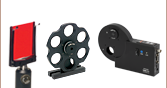
- 90° Flipping Between Two Positions
- Accepts up to Two Optic Holders
- Controlled Using Button, Handset,
External Trigger, or Software - Fully Configurable Input and Output Signals
Application Idea
MFF102
Rear View
A Typical Beam Steering Setup with
a Flip Mount in the Beam Path
Remote Handset (Included)
MFF101
Front View


Please Wait
| Specifications | |
|---|---|
| Flip Positions | 0° and 90° |
| Flip Timea | 500 ms to 2800 ms |
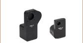
| Optic Diameterb | MFF101: 1" MFF102: 2" |
| Flip to Flip Repeatability | 50 μrad |
| Maximum Driftc | 1.0 µm2 |
| Maximum Loadd,a | 120 g (4.23 oz) |
| Maximum Torque | 0.1 N•m |
| DIG I/O Connector Typee | SMA (2 Places) |
| Power Input | 15 VDC |
| Weight (Excluding Power Supply) | 100 g (3.53 oz) |
Click to Enlarge
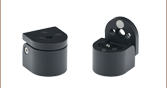
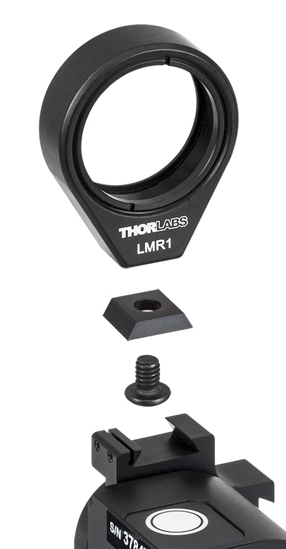
レンズマウントのブラケット、M4ネジ、止めネジの分解画像
内部のギアボックスに恒久的な損傷を与えるため、モータの駆動時にフリッパーアームを手動で動かさないようご注意ください。
特長
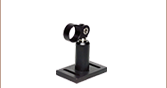
- レンズホルダ付属
- Ø50.8 mm(Ø2インチ)までのLMR シリーズならびにFMPシリーズのレンズマウントに全て対応
- 速度フィードバック制御がスムーズな移動を実現
- 繰り返し位置決め用のメカニカルストッパ
- ポスト取付け用 M4タップ穴
- フリッパーユニットは30 mm x 30 mmの小さい設置面積
- リモート操作用リモートハンドセット、1メートル長のケーブル、Kinesis®ソフトウェア一式、電源が付属
この2ポジション型高速フリップマウントは、レンズやフィルタなどの光学部品を自由空間ビーム光路中に可変式に出し入れ(フリップ)します。 下の写真の通り、同じフリッパに最大2つまでのレンズマウントを取付けることが可能なので交互に別の光学素子を使用することも可能です。 フリップを駆動する方法は4つあります。ユニット上部にあるボタン、付属のリモートハンドセット、外付けのSMAコネクタを通じた信号入力、付属のソフトウェアによるPCからの操作です(詳細は「モーションコントロールソフトウェア」、「Kinesisチュートリアル」ならびに「APTチュートリアル」のタブをご覧ください)。 フリッパの位置は切り替え時に90°時計回り、または反時計回りに移動します。切り替えは信号の絶対レベル検出(すなわち低または高電圧を選択してフリッパ位置の特定)、またはエッジ検出(制御電圧レベルを変化によりフリッパを回転させる)によって行うことができます。ユニットには両方の位置にマグネットリミットスイッチがあり、どちらの位置にフリッパがいるのかを特定できます。
Click to Enlarge
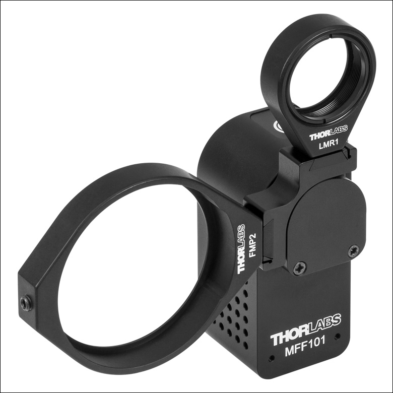
フリッパMFF101(/M)にレンズマウントLMR1(/M)と固定式レンズマウントFMP2(/M)を取付け(FMP2(/M)は別売り)
フリッパの設置面サイズは30 mm x 30 mmで、側面にはリモートハンドセットまたは外部トリガからの信号を入力するDIG I/O 1とDIG I/O 2と書かれた2つのSMAコネクタが付いています。 PC上のKinesisソフトウェアあるいは従来のAPTソフトウェアにより「In Motion」ならびに「At Position」時に信号を出力する設定も可能です。 ソフトウェア設定をユニット内に保存すれば、PCがなくてもユニットを使用することができます。
フリッパMFF101/MにはØ25.4 mm光学素子用レンズマウントLMR1/Mならびに光学素子を保持する固定リングSM1RRが付属します。フリッパMFF102/MにはØ50.8 mm光学素子用レンズマウントLMR2/Mならびに光学素子を保持する固定リングSM2RRが付属します。 当社のLMRシリーズならびにFMPシリーズの レンズマウントについては、直径が50.8 mm(2インチ)を超えないものならどれでもフリッパに取り付けることができます。 上の写真でご覧いただけるようにレンズマウントはブラケットによってフリッパに取り付けられます。 レンズマウントはM4ネジによってブラケットに、ブラケットはフレクシャークランプによってフリッパに保持されます。 フレクシャークランプは付属の0.9 mm六角レンチを使って2本の止めネジで締めます。 各フリッパーユニットには2つのブラケットと2本のM4ネジが付いています
フリッパの底面にあるM4タップ穴によりØ12 mm~Ø12.7 mm(Ø1/2インチ)ポストに取り付けることも可能です。 フリッパは付属の15 V電源で駆動します。PC制御ならびに設定のためにフリッパとPCをつなぐ1.5 m長のマイクロUSB-USBケーブルも付属します。
フリッパはミラーを含む様々な光学素子との使用に適しています。 ミラーと使用した場合、100 µrad以上のビーム安定性が必要となる用途には推奨しませんのでご注意ください。 ユニットへの締付けトルクは 0.1 N•mを超えないようご注意ください。レンズマウントならびに光学素子を含む最大耐荷重は120 gです。側面にはユニットの冷却を補助する通気口が並んでいます。通気口付近の空気の流れが遮断されていないか必ず確認してください。
デジタルI/O
SMAメス型

TTL信号レベル出力期待値
TTL(低): 0 V
TTL(高): 5 V
当社では幅広い種類のモーションコントローラを駆動できるよう、Kinesis® ソフトウェアパッケージと従来のAPT™(Advanced Positioning Technology)ソフトウェアパッケージの2種類のプラットフォームをご用意しております。どちらのパッケージも小型で低出力のシングルチャンネルドライバ(K-Cube™やT-Cube™など)から高出力でマルチチャンネルのモジュール式19インチラックナノポジショニングシステム(APTラックシステム)まで幅広い種類のモーションコントローラをカバーするKinesisシリーズのデバイスを制御できます。
Kinesisソフトウェアには、最新のC#、Visual Basic、LabVIEW™またはその他の.NETに対応する言語を使用してカスタムプログラムを作成するサードパーティの開発者向けに、.NETコントロールが付属しています。また、.NETフレームワークを使用しない用途向けに低級言語用のDLLライブラリも付いています。センターシーケンスマネージャが、当社の全てのモーションコントロールハードウェアの統合と同期をサポートします。

KinesisのGUIスクリーン
APTのGUIスクリーン
当社従来のAPTシステムソフトウェアプラットフォームは、C#、Visual Basic、LabVIEWまたはその他のActive-Xに対応する言語を使用してカスタムプログラムを作成するサードパーティの開発者向けに、ActiveXをベースとしたコントロールが付属しています。また、ハードウェア無しでカスタムプログラムの開発を行うためのシミュレーターモードも付いています。
これらの共通のソフトウェアプラットフォームにより、あらゆるKinesisとAPTコントローラをシングルアプリケーションに簡単に組み込むことができます。ソフトウェアツールは1セット習得するだけで共通した操作が可能です。シングルチャンネルシステムからマルチチャンネルシステムまで、あらゆるコントローラを組み合わせ、全てを1台のPCのソフトウェアインターフェイスから制御することが実現可能です。
このソフトウェアパッケージを使用するには2つの手段があります。GUI(グラフィカルユーザーインターフェイス)ユーティリティを使用したコントローラとの直接対話ならびに「out of the box」コントロール、またはご選択の開発言語でカスタム統合の位置決めやアライメントソリューションを簡単にプログラムできる一連のプログラミングインターフェイスです。
APTシステムソフトウェアをよりご理解いただけるために様々なチュートリアルビデオもご用意しております。ビデオではソフトウェアの概要とAPT Configユーティリティをご説明しています。また、ソフトウェアのシミュレーターモードを利用すると、コントローラを接続しないでソフトウェアを試すことができます。その方法を説明したビデオもあります。これらのビデオは「APTチュートリアル」タブ内のリンクからご覧いただけます。
ソフトウェア
Kinesis バージョン 1.14.47
このKinesisソフトウェアパッケージには、当社のKinesisならびにAPT™システムコントローラを制御するためのGUIが含まれています。
下記もご用意しております:
- 通信プロトコル
ソフトウェア
APT バージョン 3.21.6
このAPTソフトウェアパッケージには、当社のAPT™およびKinesisシステムコントローラを制御するためのGUIが含まれています。
下記もご用意しております:
- 通信プロトコル
Kinesis®ソフトウェアでは新しい.NETコントロールが使用でき、最新の最新のC#, Visual Basic, LabVIEW™、ほかの.NET対応言語を使用する開発者がカスタムにプログラムを作成することもできます。
C#
このプログラミング言語はマルチプログラミングパラダイムやマルチプログラミング言語が使用可能となるよう設計されているため、複雑な問題が簡単かつ効率的に解決できます。型付け、命令型、宣言型、関数型、ジェネリック、オブジェクト指向、そしてコンポーネント指向が含まれます。 この共通のソフトウェアプラットフォームにより、1セットのソフトウェアツールを習得するだけで、あらゆるKinesisコントローラを簡単に組み合わせることができます。このようにして1軸システムのコントローラから多軸システムのコントローラまで、様々なコントローラを組み合わせ、全てを1台のPCのソフトウェアインターフェイスから制御することが可能となりました。
Kinesisシステムソフトウェアを使用するには2つの手段があります。コントローラを直接つないで制御を行なう付属のGUI(グラフィカルユーザーインターフェイス)ユーティリティ、またはご希望の開発言語でカスタム仕様の位置決めやアライメントを簡単にプログラムできる一連のプログラミングインターフェイスです。
Kinesisモーションコントロールライブラリの構築の参考となる実行可能なプロジェクト機能拡張例については下のリンクをクリックしてください。なお、Quick Startのプロジェクト例の実行には別の統合開発環境(IDE)(Microsoft Visual Studioなど)が必要です。C#のプロジェクト例はKinesisソフトウェアパッケージに付属する.NETコントロールで実行可能です(詳細は「Kinesisソフトウェア」タブをご覧ください)。
 | Click Here for the Kinesis with C# Quick Start Guide Click Here for C# Example Projects Click Here for Quick Start Device Control Examples | |
LabVIEW
LabVIEWは、.Netコントロールを介してKinesisまたはAPTベースのコントローラとの通信に使用できます。LabVIEWでは、ツールとオブジェクトでフロントパネルとして知られるユーザーインターフェイスを構築した後、グラフィカル表記の関数を使ってコードを追加し、フロントパネルのオブジェクトを制御します。下記のLabVIEWチュートリアルでは.Netコントロールを使用してLabVIEW内KinesisまたはAPT駆動デバイス用の制御GUIを作成するための情報をご提供しています。 LabVIEWでコントローラを制御する基本的な方法や、LabVIEW GUIを用いてデバイスを操作する前に行うべき設定の手順についても解説しています。
 | Click Here to View the LabVIEW Guide Click Here to View the Kinesis with LabVIEW Overview Page | |
こちらのページでご覧いただくAPTビデオチュートリアルは、付属のATPユーティリティに関する説明と、いくつかのプログラミング環境におけるAPTシステムのプログラミングに関する説明の2つの部分から構成されています。
免責事項:これらの動画は、当初はAdobe Flashによって作成されました。2020年のAdobe Flashのサポート終了後、これらのチュートリアルは再録画されています。各動画の下にはFlash Playerの操作ボタンが見えますが、機能はしません。
APTコントローラには、APTUserユーティリティとAPTConfigユーティリティが付いています。APTUserを用いると、直感的操作が可能なグラフィック制御パネルを介して、APTで制御するハードウェアに素早く簡単に接続することができます。APTConfigは「オフライン」ユーティリティで、メカニカルステージのタイプを事前に選択し、それらを特定のモーションコントローラに対応付けるなど、システム全体のさまざまな設定を行うことができます。
APT Userユーティリティ
下の左側の動画では、APTUserユーティリティの操作概要について説明しています。シングルチャンネルコントローラのOptoDriverは、制御用のPCが無くても前面パネルのコントローラを介して操作できます。前面パネルのコントローラに保存されている操作に関する設定は、APTUserユーティリティを使用して変更することができます。そのプロセスは下の右側の動画でご覧いただけます。
APT Configユーティリティ
シミュレートされたハードウェア構成のセットアップや、メカニカルステージの特定のモータードライブチャンネルへの対応付けなど、APT Configユーティリティを使用してAPTシステム全体の様々な設定ができます。下の最初の動画ではAPT Configの概要をご覧いただけます。シミュレートされたハードウェア構成の作成方法やステージと対応付ける方法についての詳細は、その右側の2つの動画でご覧いただけます。
APTのプログラミング
APTソフトウェアシステムは、ActiveXコントロールのコレクションとして実装されています。ActiveXコントロールは言語に依存しないソフトウェアモジュールで、グラフィカルユーザーインターフェイスとプログラミングインターフェイスの両方を提供します。ハードウェアユニットのタイプごとにActiveXコントロールのタイプがあります。例えば、Motor ActiveXコントロールはすべてのタイプのAPTモーターコントローラ(DCまたはステッパ)の操作に対応します。ActiveXコントロールは多くのWindowsソフトウェア開発環境やソフトウェア言語で直接サポートされており、そのようなコントロールがカスタムアプリケーションに組み込まれると、そこに含まれるすべての機能が即座にアプリケーションで利用できるようになります。下の動画では、LabVIEW、Visual Basic、Visual C++によるAPT ActiveXコントロールの基本的な使用方法について説明しています。これ以外に、LabWindows CVI、C++ Builder、VB.NET、C#.NET、Office VBA、Matlab、HPVEEなどの多数の言語でもActiveXはサポートされています。これらの言語環境についてはチュートリアルのビデオでは特に取り上げていませんが、動画内の考え方の多くは他の言語環境でも適切に使用できます。
Visual Basic
Part 1ではVisual Basicで動作するAPT ActiveXコントロールを設定する方法について説明しており、Part 2では独自の位置決めシーケンスをプログラミングする方法について説明しています。
LabVIEW
LabVIEWはActiveXをフルサポートしています。下の一連のチュートリアルビデオでは、APTによる独自のモーションコントロールシーケンスを作製する際の基本的な構成要素を示しています。まずソフトウェア開発中にオンラインヘルプを呼び出す方法をご紹介します。Part 2ではAPT ActiveXコントロールの作成方法をご紹介します。ActiveXコントロールではメソッド(機能)とプロパティ(数値設定)の両方を設定できます。Part 3と4では、ActiveXコントロールで示されたメソッドとプロパティを作成してワイヤで接続する方法をご紹介します。最後に、Part 5では全体をまとめて、独自の移動シーケンスを実行するLabVIEWのプログラム例をご紹介します。
Part 1:オンラインヘルプへのアクセス方法
Part 2:ActiveXコントロールの作成方法
Part 3:ActiveXのメソッドの作成方法
Part 4:ActiveXのプロパティの作成方法
Part 5:ActiveXコントロールの開始方法
下のチュートリアルビデオでは、メソッドおよびプロパティのノードを作成する別の方法について説明しています。
ActiveXメソッドの作成方法(別の方法)
ActiveXプロパティの作成方法(別の方法)
Visual C++
Part 1ではVisualC++で動作するAPT ActiveXコントロールを設定する方法について説明しており、Part 2では独自の位置決めシーケンスをプログラミングする方法について説明しています。
MATLAB
当社のAPTポジショナにMATLABおよびActiveXコントロールを使用する場合は、こちらの資料をご覧ください。
プログラマー向けとして、LabVIEWでAPTソフトウェアをプログラミングする方法もこちらからご覧いただけます。
| Posted Comments: | |
robin arnaud-goddet
(posted 2024-04-22 09:01:17.887) Hello, I'm trying to control the MFF102/M with Kinesis-Labview, I was wondering if you had any VI to use as an exemple ? do'neill
(posted 2024-04-23 05:51:43.0) Thank you for reaching out. I will contact you directly with an example VI for the MFF102. Tom Dzelzainis
(posted 2024-03-22 10:01:45.547) Hi,
The description mentions that the SMA IO connectors can be configured to indicate that the device is "In position". Does this tell you which position it is in, i.e. could you tell from this whether a filter is in the beam or out of the beam, or does it just tell you that the flipper has reached an end point and is no longer in motion?
Many thanks,
Tom. cstroud
(posted 2024-04-05 05:17:16.0) Thanks for reaching out. You can see which port you're currently in by setting the output signal mode to Logic Level Output. If the Operating mode is set to Output: At Position, then a transition from LO to HI (0V to 5V) indicates that the flipper is at POS 1 and a transition from HI to LO (5V to 0V) indicates that the flipper is at POS 2. Further information can be found on pages 19-20 of the MFF101 manual. Martin Gohlke
(posted 2024-03-14 14:38:53.09) Hi ,
I'm looking for these little dovetail thing, that is needed to connect something. This part is missing in our lab and I wanted to ask you, how I can order it separately?
Can you help me?
All the best
Martin cstroud
(posted 2024-03-15 12:04:20.0) Thanks for reaching out. I will contact you directly to send over a quote for this item. user
(posted 2023-10-13 12:08:39.61) When will Throlabs implement their software to work on macOS? They have all these motion systems but they force the user to be on Windows. What if the device under test requires to be run on macOS? Can't control the station and DUT using the same computer without complicated remote control interfaces. Please don't suggest that it works on macOS using the APT low level language model, a document that's what 500+ pages long and is extremely complicated. do'neill
(posted 2023-10-18 10:41:55.0) Response from Daniel at Thorlabs. Currently as you stated, the only way to control these devices on a non-windows OS is to use the low level serial commands. I will reach out to you directly to discuss your application. user
(posted 2023-10-11 21:46:59.81) I have no way of knowing how much power is drawn by this the MFF101 flip-in filter. Do we have a max power draw for this device? Adam Smith
(posted 2023-08-01 12:20:17.903) Hi, Can you tell me the load impedance for the control signal to the SMA Dig i/o connectors (trying to spec a minimum drive current). fguzman
(posted 2023-08-07 03:49:01.0) Thanks for your enquiry. There is a 10K pull up on the trigger input to 5volts, so as long as the drive signal input can pull the 10K low. So if the drive can sink 1mA that should be fine. user
(posted 2023-04-27 18:37:44.817) Did there used to be an earlier version of this device. We supplied as part of a machine a few years ago and I think the new version is different. Do you have a datasheet for the original so we can check compatibility issues JReeder
(posted 2023-04-28 04:27:54.0) Thank you for your enquiry. The previous version of the current MFF series was the MFF001(/M). I have reached out to you to provide further details on this obsolete model. aaron reyes
(posted 2023-03-15 14:08:11.46) Do you have an older version of the solidworks or step file for this? I'm having a hard time using the file since we're running 2021. Thanks! do'neill
(posted 2023-03-16 10:21:15.0) Response from Daniel at Thorlabs. We have updated our systems and files to Solidworks 2022 and there is no way in the software to make the Solidworks files backwards compatible. I will reach out to you directly to discuss your requirements Tonino Giagnacovo
(posted 2023-01-18 14:48:16.523) I have two questions about this actuator.
1) The actuator is based on a DC geared motor? In detail, how much stable are the two stop positions?
2) We can power the unit with 12V instead of 15V?
Thanks JReeder
(posted 2023-01-19 07:43:20.0) Thank you for your enquiry. The filter flipper does indeed use a geared DC motor. The MFF flippers are not recommended for applications requiring better than 100 µrad beam stability if used (for example) with a mirror. It is possible to use a different power supply with the MFF, however this would void the warranty. The MFF requires a 15 VDC power supply in order to function up to spec and using a different voltage may cause damage to the unit. Frankie Fung
(posted 2023-01-09 19:09:33.413) Can you please provide the part number for the trapezoidal between the MFF102 and the LMR1? do'neill
(posted 2023-01-11 04:40:38.0) Response from Daniel at Thorlabs: Thank you for contacting us. Unfortunately these parts are not catalogue items and we would need to send you a quote for these. A member of your local technical support team will reach out to you to help you with this. Richard Graham
(posted 2022-09-08 11:05:01.98) I am wondering if you could provide a little more detail on the 1.0 µm2 maximum drift specification. Is the unit flipped during this testing? I am not sure that I understand why it is given in square microns.
Ideally I would like to know a specification for the translation repeatability flip-to-flip to see if this would be suitable for a pinhole mount. Thanks. cwright
(posted 2022-09-09 05:48:37.0) Response from Charles at Thorlabs: Thank you for your query. The drift is the measured movement in X and Y when the device was left in position in a temperature controlled environment. The specification is therefore an area in which the centre of the mount could move. I will reach out to you about your application. Steffen L
(posted 2022-02-23 11:17:21.64) Hello,
I use some files of your Motion Control Software "Kinesis" in my own C++ program to control the "MFF102/M".
It works fine.
What are the license terms for using your software?
Is it open-source or is it GPL?
I can not find any information about it.
Thanks!
Steffen cwright
(posted 2022-02-24 05:30:52.0) Response from Charles at Thorlabs: Thank you for your query. Our license agreement can be found here: https://www.thorlabs.com/Software/Motion%20Control/KINESIS/License%20Agreement.htm We will reach out to you to discuss this. Matt Sidare
(posted 2022-01-25 08:26:55.12) Product: MFF101 and MFF102 Motorized Filter Flippers
Question: What is the connector part number for the mating connection to the SMA TRIGGER JACK DJayasuriya
(posted 2022-01-27 06:03:19.0) Thank you for your inquiry. For the SMA trigger jack you would be able to use these SMA cables depending on your set up : https://www.thorlabs.com/newgrouppage9.cfm?objectgroup_id=2888 DJayasuriya
(posted 2022-01-27 06:03:19.0) Thank you for your inquiry. For the SMA trigger jack you would be able to use these SMA cables depending on your set up : https://www.thorlabs.com/newgrouppage9.cfm?objectgroup_id=2888 user
(posted 2021-12-16 21:32:36.237) Hello. I wonder if this can be fixed at the angle between the two units so that the beam can pass through the unit without going through it. I couldn't find anything like that in the program. If this is possible, can I write it myself with something like labview? Thanks. cwright
(posted 2021-12-17 05:06:07.0) Response from Charles at Thorlabs: Thank you for your query. No this is not possible as the motor moves between two limit switches which are used for positional feedback. THere is no mechanism to allow a move between these two points. Alex Kor
(posted 2021-11-29 16:11:16.353) I want to control MFF102 with LabVIEW and I used an ActiveX based APT plugin. What method or command do I need to use to switch it between 2 positions?or did you have any example of vi to refer? DJayasuriya
(posted 2021-12-03 03:33:56.0) Thank you for your inquiery. We have got in touch with you directly to resolve your issue. jamie laird
(posted 2021-11-24 02:39:29.553) Can you tell me the power supply ratings ? I have one but seem to have lost the supply DJayasuriya
(posted 2021-11-25 08:02:40.0) Thank you for your inquiery. The MFF uses a 15 VDC power supply. We will get in touch with you to resolve your issue. Tsai Terry
(posted 2021-09-30 15:56:26.887) I want to control MFF102 with LabVIEW and I used an ActiveX based APT plugin.
What method or command do I need to use to switch it between 2 positions?or did you have any example of vi to refer? DJayasuriya
(posted 2021-10-01 06:19:41.0) Thank you for your inquiry. Yes of course we will get in touch with you with an example VI. Martin Kunz
(posted 2021-07-15 12:16:21.64) We need to control two MFF101's from outside an X-ray hutch i.e. over a long-ish distance (~ 20 ft). We arranged this through an USB connection using an active USB extension cord. It works just fine except the connection gets lost occasionally (throwing the rets of the control software in disarray). Any recommendations how to fix this? DJayasuriya
(posted 2021-07-16 04:58:39.0) Thank you for your inquiry. USB cable exceeding 3m can affect the communication between the computer and device. Alternatively using another USB port may help. i.e.in some computers the USB ports on the front of the PC, or on one side of a laptop, may share the same internal hub. Please try connecting to ports at the back or other side if possible. Or if possible one long USB cable than with a extender may help as well. Wonseok Jeong
(posted 2021-06-03 15:50:20.047) recently APT user didn't install on latest Windows10.
I use 32bit software for 64bit Win10.
There was no problem during installation.
But I couldn't see the software screen when I click the ATP user icon. There was no reaction.
If I install it to 2019 version Win10 then it run well. DJayasuriya
(posted 2021-06-08 06:28:04.0) Thank you for your inquiry. We have contacted you directly to resolve your issue, user
(posted 2021-03-02 20:47:02.693) Hello,
What is the part number for the trapezoidal connector between the MFF101 and the LMR1? We are missing two of these.
Thanks! cwright
(posted 2021-03-04 04:42:44.0) Response from Charles at Thorlabs: Hello and thank you for contacting us. Unfortunately these parts are not catalogue items and we would need to send you a quote for these. A member of your local technical support team will reach out to you. Felipe Hall
(posted 2021-03-02 12:29:22.803) It would be great if we could select whether to download detailed 3D models of your products, or just the outer shell. Products such as the MFF101 have way too much detail to be effectively used on large optical benches. Many of your linear stages are the same way. Just a thought. cwright
(posted 2021-03-03 12:03:11.0) Response from Charles at Thorlabs: Hello and thank you for your feedback! We will pass this information along to our engineers and webteam. user
(posted 2021-02-02 22:35:48.487) Does the 2" flip mount work in all gravity vectors? I'm looking to put this on an instrument on the backend of a telescope. Thanks! cwright
(posted 2021-02-04 04:11:10.0) Response from Charles at Thorlabs: Hello and thank you for your query. This device could be used in positions other than upright, although it was not designed for that, but if the filter mount is not at the forward or reverse limit switch on power up then it may need to be initialised manually via the button or Kinesis. This would depend on the orientation and load at power up.
However, I am not entirely clear how this will be used in your application and I will reach out to you directly to discuss this. Fabian Brunner
(posted 2021-01-14 11:22:21.067) Hi!
I'm trying to control the flip mount from a C++ program but I always receive an 'LoadDevice failed' message from the FF_Open method of the ThorLabs.MotionControl.FilterFlipper.dll.
In the latest version of the Kinesis software the communication with the flip mount works perfectly. And also in the C++ program the device is found and eg. device information can be read. Only 'opening' the device doesn't work for some reason. Do you maybe have an idea of what could be the cause of this? I tried building the device list as well as closing the device before calling FF_Open without success.
Thanks and kind regards!
The returned error code is 3 and the error message reads '01/14/21 15:41:57.679 1131 Info Loading Device Settings List (Success)
01/14/21 15:41:57.679 1131 Info Loading Custome Settings List (Success)
01/14/21 15:41:57.679 1146 Diagnostics RegisterDeviceSettingsFactory
01/14/21 15:41:57.679 1111 Info Loading Device Configurations
Device = General
01/14/21 15:41:57.679 1110 Info Reading Device Configurations
Device = General
01/14/21 15:41:57.679 1120 Info Loaded General Settings
OutputDebugMask = 7
OutputLogMask = 31
LoadSettingsOption = 2
01/14/21 15:41:57.679 1111 Info Loading Device Configurations
Device = 37003367
01/14/21 15:41:57.679 1110 Info Reading Device Configurations
Device = 37003367
01/14/21 15:41:57.679 1100 Info Loaded Device Settings
CollateLogging = 0
SettingsName = FilterFlipper
OutputDebugMask = 7
OutputLogMask = 31
DeviceAlias =
LoadSettingsOption = 2
01/14/21 15:41:57.679 1112 Info Storing Device Configurations
Device = 37003367
01/14/21 15:41:58.805 37003367 Error LoadDevice Failed' DJayasuriya
(posted 2021-01-15 11:34:25.0) Thank you for your feedback. I will reach out to you directly to resolve this issue. Cathy Jiang
(posted 2020-12-02 14:33:29.78) Hi I'm looking for a filter motor that is going to be used in automated test equipment. I'm interested in knowing:
1. the highest speed of switching speed
2. if it has been rated for maximum number of runs above 100k times?
3. If the controller gives feedback on the actual position? So if the motor stops working, the testing software gives error message. DJayasuriya
(posted 2020-12-11 08:18:19.0) Thank you for your inquiry. The switching time would depend on the load on the mount, however we spec between 500 ms to 2800 ms. The number of runs also depends on the pay load. If the payload was relatively small we would think it would get fairly close 100 K runs. There is no position feedback only the limit switches at the end of the MFF101. I guess this could be used for a failure mode as by definition when you activate the flipper you know that the current limit switch is active and you know that roughly after the flight time the other one should. In the status bits returned the state of each limit switch is available.
Hope this helps, please get in touch with our tech support team if you would have any questions regarding your application. Tony Denault
(posted 2020-09-30 19:09:57.337) I wish to use this with only DIG input/output (w/o a PC in the loop). Would "Input: Goto Position" mode always set the unit to know a position at power up based on the input?
What is the "enable" on the software? If power was re-cycled on the unit, shouldn't up come up "enable"?
Can I use this only with DIG1 (button input) and DIG2 (output, at position).
Is using a long transit time (2800 ms) best. 3 seconds is no problem for us, is a longer transit time easier for the unit (longer life, etc)? cwright
(posted 2020-10-06 11:38:20.0) Response from Charles at Thorlabs: Hello and thank you for your query. Our technical support will reach out to you directly in regards to your application due to the length and depth of your questions. Gerold Kloos
(posted 2020-09-13 22:27:44.877) Hi
Can you please advise what the power requirements for the filter flipper MFF102/M are?
It's 15V, what current, what power?
Thanks
Gerold YLohia
(posted 2020-10-23 10:23:21.0) Hello Gerold, thank you for contacting Thorlabs. The power supply used for this MFF flipper will output 15V and up to 2.4A (36 W). The device will draw varying levels of current during use -- this can depend on the load and the filter position. Mikhail Olegin
(posted 2020-08-08 21:25:31.643) I can't use this flip mount with logic edge input and go to position option without software, because flip mount doesn't enable themself on start. Each time I need to connect with PC and push Enable button. Do you have any solutions of this problem? DJayasuriya
(posted 2020-08-14 04:46:28.0) Thank you for your inquiry. Please ensure that the settings has been persisted into the IO ports so that on power up the mode is correct to operate. The remote input will not work until the button on the unit has been pressed. So you would need to ensure that when the flipper is powered down the payload with gravity will take it to one end stop or another, so that on repower the remote input will work.
The reason being there is no position feedback other than the two end positions so if a trigger signal happens to be active on power up and it is in an unknown state it could just move inadvertently anywhere, which may cause problems/damage. So you have to physically push the button on the unit in these circumstances.
If you have any questions do not hesitate to get in touch with your local tech support team Warren Massey
(posted 2020-07-06 16:21:00.09) When either of the SMA/Digital-I/O ports is configured as an output, how much current can they source and sink? DJayasuriya
(posted 2020-07-17 07:06:18.0) Thank you for your inquiry. These outputs are open collector with a 10K internal pull up so they have to drive a relatively high output impedance.
So the output can sink more than it can source. Say nominally 100 micro-amp source and 10 milli-amp sink.
If you would wanted to drive a low impedance it would need a buffer of some sort in between. HYESANG KIM
(posted 2020-04-23 11:51:56.933) Hello, I got your reply and tried it, thank you. But I got problem with it. The error message "Object reference not set to an instance of an object" (with source : Thorlabs.MotionControl.PrivateInternal)
I think I should use FilterFlipperCLI.dll but yours isn't. If I could've help with it, I would be very thankful. DJayasuriya
(posted 2020-04-24 07:55:48.0) Response from Dinuka at Thorlabs: Thank you for your feedback, I will be in contact with you directly to help troubleshoot your programming issues. HYESANG KIM
(posted 2020-04-23 04:55:21.59) I am trying to interface with the MFF101/M via using kinesis in MATLAB. If I could have help with any general suggestions with interfacing via MATLAB, I would be very thankful. DJayasuriya
(posted 2020-04-23 10:34:03.0) Response from Dinuka at Thorlabs: Hello, thank you for your inquiry. You will be able to use the communication protocall to send messages to the controller. I will get in touch directly to help with your application. DJayasuriya
(posted 2020-04-23 10:34:03.0) Response from Dinuka at Thorlabs: Hello, thank you for your inquiry. You will be able to use the communication protocall to send messages to the controller. I will get in touch directly to help with your application. ioannis Theodonis
(posted 2019-12-21 19:53:28.993) can we use these to rotate the lambda/2 plates in QKD demonstration experiments through distance over internet? cwright
(posted 2020-01-03 12:24:23.0) Response from Charles at Thorlabs: Hello Ioannis, unfortunately these do not have an ethernet port or a wireless connection to directly facilitate this. The only way I can think to achieve remote control over the internet would be to remotely log in to the controlling PC. Dor Saddan
(posted 2019-12-09 02:30:27.917) I want to use the MFF102/M to flip 2 optical assemblies in/out of a vertical optical axis, i.e. - the unit will hold a ST1XY-S/M + camera in one point and a K5X1 in the other.
What is the maximal loading capacity of the unit in this vertical state? cwright
(posted 2019-12-11 04:18:27.0) Response from Charles at Thorlabs: Hello Dor, unfortunately these devices have not been characterised for a load capacity in anything other than their upright state i.e. a horizontal optical axis, where the limit is 120g. They were only intended for low load capacity applications however and the maximum torque which can be applied is 0.1Nm. Your local technical supprot team will reach out to see how we can help you with your application. Chris Armstrong
(posted 2019-12-02 08:22:32.59) It would be good if we could purchase or request in the initial order additional lens mountings and crucially the small bracket to attach them to the flipper. Often it is useful to have multiple optics or filters mounted to a specific angle and then switch them between flipper motors.
Cheers,
Chris. cwright
(posted 2019-12-03 11:21:26.0) Response from Charles at Thorlabs: Hello Chris. Thank you for your feedback. I can certainly see how this would be useful for some customers and will ensure this idea is put forward for consideration. For now, I will contact you directly to see how we can address your needs. Yaniv Yirmiyahu
(posted 2019-12-02 08:19:21.053) I received two MFF101/M without any "location specific adapter " for the two KPS101 power supplies.
S/N: 37002123 & 37002124
23-Sep-19 cwright
(posted 2019-12-03 11:11:13.0) Response from Charles at Thorlabs: Hello Yaniv. I will contact you directly to get your order details and ensure these are sent out to you as soon as possible. Marty Stevens
(posted 2019-10-11 16:19:16.147) What is the part number for the small trapezoidal bracket for mounting an LMR1 or LMR2 optic holder to the flip mount? I already have the flip mount, but we seem to have lost our adapter brackets. AManickavasagam
(posted 2019-10-15 07:56:16.0) Response from Arunthathi at Thorlabs: Thanks for your query. I have contacted you directly with the part number and further details. Chris Purves
(posted 2019-10-04 13:27:56.777) I'm having a lot of trouble getting the MFF101 to work with LabVIEW using the Kinesis drivers. My problem with is that I cannot get them to work without creating a LabVIEW project. This does not work with our design structure. I have tried loading the .NET drivers into the GAC, but that also didn't work. Do you have instructions for using Kinesis drivers without creating a LabVIEW project? Thanks. AManickavasagam
(posted 2019-10-09 06:51:58.0) Response from Arunthathi at Thorlabs: Unfortunately, you will need to create a LabVIEW project to sort the DLLs for it to work. The .NET assemblies are standard dlls (non-Active-X/COM) that are not easily stored in the Windows Registry. Thus, there are some application-dependent requirements on where the DLL files are required to be stored to run properly. user
(posted 2019-09-26 14:10:55.793) I'm not able to connect to MFF101 using either APT or Kenisis GUI. I'm using the latest version of the software with Windows 10. The flipper does not show up in Device Manager. I've tried two different flippers; no response from either one. rmiron
(posted 2019-09-27 09:16:31.0) Response from Radu at Thorlabs: I am sorry to hear that you are experiencing this connectivity issue. It might be that the USB port or its associated circuitry got damaged in transit. I will send you troubleshooting instructions directly so that we can precisely identify the reason behind this. VIC MCCARN
(posted 2019-07-31 17:19:06.627) I may need to power the MFF101 with a different power supply. What is the tolerance on the 15V input? AManickavasagam
(posted 2019-08-02 10:16:00.0) Response from Arunthathi at Thorlabs: Thanks for your query. Just to point out the warranty on this item would be void once used with a different power supply. However, should you wish to proceed that route the initial set accuracy on the voltage would be ±5% at 50% load. Sooyoung Park
(posted 2019-04-03 01:28:03.61) Hello.
I'm a graduate school student in Korea University.
I'd like to purchase MFF101/M.
But I have two questions after I read the manual.
1. First question
There is the explanation about 'stability' in chapter 2.1.
It is written that 'When used with a mirror, please note that the unit is not recommended for applications requiring better than 100 µrad beam stability. '.
What does it mean?
Does it mean that the mirror would be oscillating in angular range of 100 µrad?
If then, what is the period of the oscillation?
2. Second question
There is information about 'repeatability' in Appendix B.
But there are two kinds of repeatability.
One is 'flip to flip repeatability' and the other is 'angular repeatability'.
What is the difference?
Thank you.
I'm looking forward to seeing your answer. rmiron
(posted 2019-04-11 09:36:17.0) Response from Radu at Thorlabs: Hello, Sooyoung. The beam stability specification refers to how much the reflected beam can drift by (with respect to the input beam). We can't specify a frequency for this drift for two reasons: we did not attempt to measure it and the test data we have on-hand suggests that it is a chaotic motion, as opposed to a harmonic oscillation.
The repeatability specifications refers to the angular variation of the plane in which the optical mount lies. If it is flipped from position 1 to position 2 and back to position 1, this plane can tilt by up to the figure we specify for flip-to-flip repeatability (the same holds true for position 2 to 1 and back). Over time, after many flips, the orientation of the mount's plane can change by up to the angular repetability specification, but not by more. eoldewur
(posted 2019-01-24 22:00:06.56) Hi, is it possible to use the motorized flipper in a continuous fashion, e.g. flipping every 1 or 2 seconds for many hours? What is the expected life-time of the device? Thanks! bhallewell
(posted 2019-01-25 06:28:11.0) Response from Ben at Thorlabs: Whilst we don't have a formal test specification for lifetime for this device, we do have some nominal test data which may be of use to you. I will contact you directly to discuss this with you. qiyu4227
(posted 2019-01-24 09:01:52.837) Hi, I want use APT on Windows XP (32 bit) with Labview 8.2 (32 Bit). But no previous version of APT could be found. Is there anything compatible you could suggest or provide?
Thank you! bhallewell
(posted 2019-01-24 11:01:24.0) Response from Ben at Thorlabs: I will contact you directly to provide you with an older 32-bit version of APT for XP. Please bear in mind that this may have reduced functionality compared with the latest version available on the website. marcus.held
(posted 2018-10-01 10:41:22.973) Dear Thorlabs-Team,
I would like to ask how the SMA DIOs are connected.
I installed at the DIO1 a TTL signal and at DIO2 the remote handset. A switching either with the handset or an TTL signal connected to DIO2 is not possible.
It would be very beneficial if DIO2 can be used in addition to DIO1.
I appreciate any help and best regards,
Marcus Held rmiron
(posted 2018-10-02 06:54:54.0) Response from Radu at Thorlabs: Dear Marcus, you should be able to set both ports in the same operating mode (I assume this would be "Input: Toggle Position" in your case). With that being said, there might be situations in which the controller receives conflicting commands via the two ports, causing it to not operate as expected. I will contact you directly to check what is going wrong in your case. jskim84
(posted 2018-08-28 21:25:04.513) Hello, I am Jung-Su Kim in EOTECHNICS.
I hope to use MFF101 Flipper motor.
What is the operating current?
- Voltage : 15VDC
- Current : ?
please answer about my question.
best regards,
JSKIM rmiron
(posted 2018-09-03 04:47:35.0) Response from Radu at Thorlabs: Thank you for contacting us, Jung-Su. The maximum current that MFF101's power supply can draw is 2.4 A. gino.lopes
(posted 2018-08-07 11:26:27.853) Followed the LabVIEW guide for dotNET Kinesis drivers, works ok when controlling the MFF102/M Filter Flipper in the LabVIEW programming environment. When I compile the code I get an error displayed in the dotNet container on the front panel stating that the control cannot be loaded. Copied the KInesis folder to the same directory as the exe. Using LabVIEW 2014 and dotNet 4.0. rmiron
(posted 2018-08-08 05:51:04.0) Response from Radu at Thorlabs: Thank you for contacting us. I will reach out to you directly in order to troubleshoot this issue. user
(posted 2018-07-16 21:15:28.123) Our application, needs to query the serial # for the MFF102. But, when we issue MGMSG_HW_GET_INFO the serial # always returns 0. After chatting w/ tech support, it seems this issue will be addressed in the next firmware release. Can I get a date when this will be available ? bhallewell
(posted 2018-08-14 03:44:56.0) Response from Ben at Thorlabs: To clarify - the serial number is programmed onto Flash memory within the MFF PCB during our Production processes such that this can be retrieved through MGMSG_HW_REQ_INFO / MGMSG_HW_GET_INFO. We would be able to re-program your unit at our manufacturing site. Please contact your local Tech Support office so we can look into arranging this. fangchunyu
(posted 2018-07-05 15:34:10.647) I want to control MFF101 with LabVIEW and I used an ActiveX based APT plugin, my question is:
What method or command do I need to use to switch it between 2 positions? AManickavasagam
(posted 2018-07-16 06:06:55.0) Response from Arunthathi at Thorlabs: Thanks for your query. I have contacted you directly with a lab view VI we created for you, which could be used to switch between positions and further guidelines for the methods you could use. garcia32
(posted 2018-07-03 10:06:04.22) MFF101: We are having lost of problems with the APT software, hanging for unknown reasons at start-up.
WE would like to control it directly using TTL signals, but not enough information is provided.
How long has to be the pulse, is the operation pull-up or pull-down?
What is the required duration of the pulse?
Best, Victor rmiron
(posted 2018-07-04 12:53:09.0) Response from Radu at Thorlabs: I am sorry to hear about your issues with APT. Over the past couple of years, our efforts have mostly gone into improving Kinesis. Therefore, you might have a better user experience with this newer software.
Regarding the trigger ports, the operation is pull-up for both of them. They are in the HIGH state by default. I can't give you a precise figure for the minimum pulse duration, but the rate at which the state of the input port is polled is above 10 kHz. Therefore, every pulse that is above 100 microsecs long should be detected. adavid
(posted 2018-02-22 16:28:41.403) I am using an old version of APT (1.0.22) on Windows XP. I use it with various stages connected to TDC001 cubes without issue.
I have recently acquired an MFF101 motorized mount, connected by USB. The mount shows as "APT USB device" in the Windows hardware manager, so it looks like the driver installed without issue. However, the MFF101 doesn't appear in the APT User software.
* Do I understand correctly that the MFF101 should show up directly in APT User? Or do I need to configure it in APT Config first? if so, how? (it doesn't show up as a motor like other stages in the Apt Config pull-down menu)
* Or, is the NFF101 not showing because my APT version is too old? If so, where can I find a software version compatible with win XP which would recognize this stage?
Thanks! bhallewell
(posted 2018-03-01 05:38:41.0) Response from Ben at Thorlabs: Thank you for your feedback. This version of APTUser you’ve referenced is a part of the following APT Software Versions
2.11.0 (Released 17-09-10)
2.12.0 (Released 09-05-11)
2.13.0 (Released 23-01-12)
The MFF* series was released at the end of 2013. I have a more recent Windows XP compatible version of Software I will send you which includes support for the MFF* series mount. It is worth checking the Change Log for our APT Software for awareness of changes in functionality across software updates. An icon for this can be found next to the Download icon for APT.
https://www.thorlabs.com/software_pages/ViewSoftwarePage.cfm?Code=Motion_Control marc.kraemer
(posted 2017-10-16 09:30:34.943) When I operate the motorized filter flip by remote control or by the button on the housing it does not change between Position 1 and 2, it only compensates gravity. I want to use the filter flip without connection to a PC. What can I do to make the filter flip work properly? I hope you can help me. Tank you in advance! bwood
(posted 2017-10-18 06:28:09.0) Response from Ben at Thorlabs: Thank you for your feedback. I will be in direct contact to troubleshoot the issues with your device. nhuffman
(posted 2017-07-25 10:06:53.76) I am trying to interface with the MFF via two ways in MATLAB. First, using the APT, and second, with the .NET API.
I have successfully got the motor to flip with the APT using the MoveJog command, but after the filter flips, the program keeps running, and I receive a Hardware Response Timeout error.
I successfully downloaded the Kinesis folder, but when I try to load the .NET dlls into MATLAB, I get the following error:
"Message: Could not load file or assembly 'file:Thorlabs.MotionControl.DeviceManagerCLI.dil' or one of its dependencies. The system cannot find the file specified.
Source: mscorlib
HelpLink:
If I could have help with one or both of these issues (or any general suggestions with interfacing via MATLAB), I would be very thankful. bwood
(posted 2017-07-27 04:21:27.0) Response from Ben at Thorlabs: Thank you for your feedback, I will be in contact with you directly to help troubleshoot your programming issues. user
(posted 2017-06-14 08:39:36.593) I was hoping to use the Motorized Filter Flip Mount on a python language. Is there some software, or help, to achieve this? Thanks bwood
(posted 2017-06-15 09:33:15.0) Response from Ben at Thorlabs: Thank you for your feedback. The software used to control the MFF series flipper mounts, Kinesis, has a full .NET API for integration with third party software. I would suggest taking a look at the ".NET API Help" file, which is installed with Kinesis, for advice on how to use this API. user
(posted 2017-05-10 12:36:00.41) The MFF201 outputs: there is only one output, the "in motion" indicator? Isn't there a position readout, a bit indicating which state it's flipped to? nbayconich
(posted 2017-06-12 03:34:18.0) This can be achieved by configuring the Dig Output as ‘At position’.
If the logic is not inverted then you will get a 'Logic High' output at the point in time when move has finished after the transition from CCW to CW position & 'Logic Low' if going in the opposite direction again at the point in time when move has finished after the transition from CW to CCW position.
If the logic is inverted then you will obtain an inverted response to the above. weihua.dong
(posted 2017-03-03 05:11:23.34) Hi
For MMF102/M, because it only include one LMR2/M.
If I need two, which part number need I need added ? I guess:
LMR2/M + Bracket m4, what is the part number for Bracket ?
best regards,
Weihua bwood
(posted 2017-03-06 10:38:00.0) Response from Ben at Thorlabs: Thank you for your feedback. The MFF102/M is provided additional bracket to mount another LMR mount, as you propose here. However, we are more than happy to provide the part number for an additional bracket, if you need one. We will be in direct contact with more details about this shortly. massey4
(posted 2017-02-28 17:15:01.957) 1) Do the MFF devices have internal sensors such that, upon power up and without being commanded to move, they can determine and accurately report (when asked) the position state (up/down/in-between) of the device?
2) Upon power up, does the device try to move to one of the end states if it is between states?
3) What is the worst case idle power dissipation for the MFF102 when it is supporting a maximum weight optic against gravity?
4) What is the idle power dissipation when it is not having to support an optic? bwood
(posted 2017-03-01 10:06:33.0) Response from Ben at Thorlabs: Thank you for your questions, let me address them in turn: 1) Yes, upon power up the MFF will detect the position of the flipper arms. 2) If the MFF is between positions when powered on, the device will stay in that position until ordered to move.3 and 4) The idle power consumption will be mostly independent of the load on the MFF, and so the current draw will be in the region of 75 mA to 120 mA. Therefore the idle power consumption would be a maximum of 1.8 W. user
(posted 2016-12-05 07:36:45.9) I was hoping to use this device on a table that also has some sensitive cavity locks running. I would like to know how much noise / vibration are created by the motion and whether there is a video available of the mount flipping between it's two states? Many thanks bwood
(posted 2016-12-06 11:00:23.0) Response from Ben at Thorlabs: Thank you for your feedback. The vibration transferred to our optical surface will strongly depend on how the MFF is mounted. I would suggest contacting your local tech support office, who will be able to discuss your application, and provide the video you have requested. cdhamley
(posted 2016-11-03 08:32:37.177) Would like enable logic on MMF101. I use this mount for a mirror to dump a beam for protection of our system since no shutter can handle the pulse energy. It would be useful if the firmware/software allowed one of the inputs to be configured as an interlock/enable. If logic LOW(HI) it will move to the set "safe" position. If logic HI(LOW) then the position is can be varied by software or the other input. Currently I can only accomplish this by using the logic level inputs to control the position and setting up external logic gates. This means I cannot control the position through the Kinesis software but must instead set up a logic output on other hardware. Hopefully this can be implemented with a firmware update to the device. bwood
(posted 2016-11-03 09:15:32.0) Response from Ben at Thorlabs: Thank you for you comments about the MFF101. While I believe you have developed the best method possible with the current functionality, I can see the usefulness of an interlock/enable setting. I will pass on your comments to our engineers. mapope09
(posted 2015-05-19 10:08:28.09) I am using the MFF102 in an automated setup and want to control it using, a different program than the APT and Labview (I use Igor). When plugged into a USB hub my computer does not recognize it has a com port, I want to get your thoughts as to what my computer is likely viewing it as and what commands to use to control it remotely. Thanks, Michael bwood
(posted 2015-05-21 06:42:37.0) Response from Ben at Thorlabs: Thank you for your feedback. You will need to set up a virtual com port in windows, through device management, to operate the device through USB communications. I will contact you directly with a guide on how to do this, and information on the commands available to be used with the MFF102. potentiostat
(posted 2015-01-28 17:50:34.397) I am using the MFF101 in Labview well.
I wanted to install your 32bit APT software under windows7 64bit but I could not.
Our Labview application was built under 32bit windows system.
So I should install the 32bit APT software under Windows7 64bit in C:\Program Files (x86). jlow
(posted 2015-01-29 02:00:35.0) Response from Jeremy at Thorlabs: You should download and install the "32-bit software for 64-bit Windows" version of the APT instead. You can find the download page at http://www.thorlabs.com/software_pages/ViewSoftwarePage.cfm?Code=APT mszheng
(posted 2014-09-03 20:18:24.287) I'm trying to control the MFF101 in LabVIEW following your guide found here: http://www.thorlabs.us/images/TabImages/GuideToLabVIEWandAPT.pdf, but when I got to the step to insert ActiveX object I couldn't find a control for this in the selection menu. The MFF flipper responds using the APT User software. What's the simplest way to toggle this thing in LabVIEW? bhallewell
(posted 2014-09-04 06:42:01.0) Response from Ben: Please firstly ensure that you have installed the correct version of APT Software depending upon your operating system. This can be retrieved from the following weblink.
http://www.thorlabs.de/software_pages/ViewSoftwarePage.cfm?Code=APT
If you are using the incorrect version then the APT ActiveX objects will not appear within the LabVIEW dropdown box. The ActiveX methods for the flipper are retrieved when you insert the MG17Motor object into your Front Panel.
To move the flipper, use the MoveJog method whereby the IJogDir parameter controls which direction the filter will flip. The LLGetStatusBits method can also be used to know your current position. paul-emile.aldebert
(posted 2014-05-12 09:52:36.16) I need to drive some MFF101/M motor with Labview. I used the guide to LV and APT, but the activeX window is too voluminous for my application, I'd like to know how to drive my motors with a toggle button on LV. I could program it but I don't know what messages are sent by APTuser on the serial port to switch the position of the MFF. Can you give me any informations about it ? Thank you for your answer msoulby
(posted 2014-05-12 10:44:47.0) Response from Mike at Thorlabs: It is possible to change the status of the filter flipper and query its state in Labview. To move the flipper you need to use the MoveJog motor method; with enumeration for IJogDir set to 1 = move clockwise or 2 = move counter clockwise. To query the status of the flipper you can use the method LLGetStausBits and use bits 0 and 1. One of these is for the UP state and one for the DOWN state. barry.coyle
(posted 2014-04-03 10:45:32.193) I need a software download for the MFF102 motorized flip mirror mount. I've lost my disk. Please advise quickly.
thanks
Barry Coyle cdaly
(posted 2014-04-03 11:07:51.0) Response from Chris at Thorlabs: The download for the APT software can be found here: http://www.thorlabs.com/software_pages/ViewSoftwarePage.cfm?Code=APT I will see if we can get a link added to this webpage to make it easier to find in the future. piel
(posted 2014-03-24 08:41:15.557) I got a couple of MFF102s and need to drive them from a Linux computer. The device is seen as a USB serial interface fine, but I can't find the right serial port settings and the correct commands to send. Could you let me know the right baudrate/parity/stopbit values for the serial port as well as the list of commands accepted?
That hopefully should be all I need to get the device working under Linux :-) msoulby
(posted 2014-03-24 11:54:03.0) Response from Mike at Thorlabs: The virtual comm port settings are as follows: Baud Rate = 115200 bits/sec; Flow Control = RTS/CTS; Bits per word = 8; Number of stop bits = 1; Parity = NONE. I have also contacted you directly on how you can determine the correct messages to send to and from the controller using our APT hardware logger. potentiostat
(posted 2014-03-20 08:46:38.6) I bought the MFF101. I want to use 'Move sequencer' in APT user software. Is it possible?
If yes, please explain how to input the parameter. bhallewell
(posted 2014-03-20 11:48:19.0) Response from Ben at Thorlabs: We greatly appreciate your feedback here. The 'Move Sequencer' utility in APTUser is not currently compatible with the MFF101. In light of your feedback however we will be updating our software to make this functionality available. I will contact you directly with more information. david.lee
(posted 2014-02-27 13:14:19.473) I have just taken delivery of a MFF101/M. When I set it up I noticed that it vibrates when you touch it and occasionally flips when touched. I suspect the device is sensitive to minor changes in voltage caused by touching it. When I wore latex gloves the vibration did not occur. I measured that the device floats at about -0.4 Volts. Has anyone at Thorlabs experienced this issue? bhallewell
(posted 2014-02-28 06:20:22.0) Response from Ben at Thorlabs: We appreciate you providing this feedback. I will contact you directly to troubleshoot this issue. mukphyzics
(posted 2014-01-10 04:06:57.62) Is the flip mirror mount MFF101/M and MFF101/M vacuum compatible. If not is there any vacuum compatible motorized flip mirror mount for 1" and 2" available with thorlabs. msoulby
(posted 2014-01-10 11:27:17.0) Response from Mike at Thorlabs: unfortunately the MFF101/M are not vacuum compatible. The product is made from anodised aluminium and contains a number of plastic/rubber parts that would outgas within a vacuum environment. cbrideau
(posted 2013-11-05 13:34:51.68) As asked by "plascottages" way back in 2011, is there a plan to integrate position information into the mount? A pin with logic high for 'mount is up' and low for 'mount is down' would be extremely useful. Alternatively, switch the control from latched to absolute, I.e. 0v at SMA connector lowers the mount while 5v raises it, rather than the edge-triggered toggle used now. msoulby
(posted 2013-11-21 11:49:28.0) Response from Mike at Thorlabs: Everything you have mentioned will be incorporated into the functionality of the new flipper. This is still currently in the final stages of testing and development but hope to have this updated version released in the near future. katonag
(posted 2013-05-13 12:52:23.063) Could you tell me the mechanical precision of the MFF01? the variability of the angle of the content? e.g. if I put a mirror in it, how much pointing precision I can expect? sharrell
(posted 2013-05-15 10:50:00.0) Response from Sean at Thorlabs: Thank you for your feedback. Unfortunately, we have not measured the pointing accuracy of the MFF001. We are planning to release a replacement for the MFF001 soon, and based on your feedback we have added the pointing accuracy to the list of specifications we will measure for the new product. I will contact you directly to see if we can offer additional support for the current MFF001. tcohen
(posted 2012-07-10 14:37:00.0) Response from Tim at Thorlabs: This product uses a TTL logic 5V high pulse trigger via the SMA female. As one example, you could use a DAQ card controlled by your PC for this operation. suneil.rudra07
(posted 2012-07-05 07:18:14.0) Is there any way of triggering this unit from a PC?
Thanks bdada
(posted 2012-01-31 12:01:00.0) Response from Buki at Thorlabs:
Thank you for using our feedback forum. The MFF001 requires a 15V 1A power supply to operate correctly. Please contact TechSupport@thorlabs.com if you have any questions. werner.poeltinger
(posted 2012-01-18 08:39:04.0) Hello ! I need additional the total Power Consumption of the MFF01. 15 V + ?? Watts or Amps
Thanks in advance user
(posted 2011-12-05 13:51:32.0) A response from Tyler at Thorlabs: I tested one unit of the MFF001 to measure the beam deviation as the mounted mirror was flipped into and out of position. The measurement was made using a BC106-VIS beam profiler that measured the centroid of the reflected beam. The MFF001 should not be used in an application that requires better than 100 micro radian stability in the beam deviation from a beam reflected off a mirror mounted in the MFF001. user
(posted 2011-11-30 14:30:55.0) A response from Tyler at Thorlabs: The MFF001 could certaily be used to hold a mirror but I don't have a reflected beam deviation specification. I would be happy to get one into the technical support lab and make a measurement that could be used as a guidline for the devices performance as a mirror flip mount. sales.lwsolutions
(posted 2011-11-29 05:48:42.0) Would you recommend the device for flipping a mirror in and out of the beam. What is the beam pointing deviation from using it this way? bdada
(posted 2011-09-21 14:23:00.0) Response from Buki at Thorlabs:
We will contact you with an update on the design changes and provide you with more information on the power supply voltage. We will also update our website with this information.
Please contact TechSupport@thorlabs.com if you have further questions. plascottages
(posted 2011-09-02 10:47:17.0) Hi. Could you give me an update on when the design changes will be ready to integrate position information. Also could you tell me the tolerane on the power supply voltage - could it run from 12V?
Thanks jjurado
(posted 2011-05-19 15:08:00.0) Response from Javier at Thorlabs to richardson: Thank you very much for your feedback. We will be implementing some design changes to this mount in order to integrate position information. We will contact you directly to keep you updated on the progress of this project. richardson
(posted 2011-05-19 11:58:49.0) We have committed to using this product in a remotely controlled apparatus and are also concerned about the method of control. It certainly would be better to have remote control of the flipper state (e.g., 5v for up, 0v for down). Also, the output should tell you the current state, not that the stage is flipping. We have asked customer support if there is a known way to modify the existing units. jjurado
(posted 2011-05-11 09:11:00.0) Response from Javier at Thorlabs to last poster: Thank you very much for your feedback. We will modify the design of the MFF001 in order to integrate position information into the mount. Please contact us at techsupport@thorlabs.com for status updates. user
(posted 2011-05-10 06:04:47.0) It would be hugely more useful if this device switched to one state at 0v and another at 5v rather than just toggling. I understand it is trivial to make a little circuit to emulate this but without an end-sense for position it is not reliable.
Any chance youll offer a modification?
I suspect >95% of users would prefer this interface. tor
(posted 2010-11-22 13:39:58.0) A response from Tor at Thorlabs to Ed: Thank you for your interest in our Motorized Mirror Flipper. Our testing shows good repeatability up to the 500-hour mark. We havent tested it beyond that, so we dont have a spec on MTBF. The torque applied to the MFF001 must not exceed 35 N·mm. The MFF001 requires a 15-V, 1-A source -- the recommended after-market supply would be the TPS001: http://www.thorlabs.com/NewGroupPage9.cfm?ObjectGroup_ID=1710 ewetherell
(posted 2010-11-19 04:08:20.0) do you have an estimated life - number of cycles, MTBF, etc. for this product? would any periodic maintenance be needed to achieve, or exceed, this lifetime?
also, id like some more details on the power supply - current requirement and connector specification.
thanks -ed thorlabs
(posted 2010-10-01 09:46:35.0) A response from Oli at Thorlabs to t.godden: The MFF001 can indeed take a TTL trigger, any rising edge going above 4.8v will cause it to trigger. The easiest way to achieve this manually is to use the MFFH01 remotely or from the button on the top. t.godden
(posted 2010-10-01 03:58:06.0) We would like to remotely control the motorized mirror filter flippers MFF001 we recently purchased. I understand it uses a TTl voltage trigger 5V. Could you please recommend/advise me a source for such a trigger. Can we use a standard DC power supply 5V and switch it on and off rapidly and if, so what length of pulse do we need? Many thanks, apologies for my ignorance on TTl!! Thorlabs
(posted 2010-09-13 09:46:10.0) Response from Javier at Thorlabs to juergen.bosse: Thank you very much for your feedback. The current design of the MFF001 motorized flipper does not feature a sensor that allows retrieval of the actual position of the flipper. However, you can use the Trigger In/Out connections on the flipper for this purpose. I will discuss a more straightforward way of determining the flippers postion with our design engineers and keep you updated. juergen.bosse
(posted 2010-09-08 11:02:20.0) Hi there. Do I read the documentation correctly that there is no static indication of the 0deg or 90deg flip position? If a maintenance person, or, worse, the end user is entering our automated environment, we fear that they might "test" the flip mount and might leave it in an unexpected state. Since we have no way of knowing the actual state at boot time of our controller, this would require some extra work. Is there an optional sensor to tell us 0deg or 90deg? Thanks, Juergen. apalmentieri
(posted 2009-12-30 12:59:43.0) A response from Adam at Thorlabs to Tom: Tom, I am sorry, but we removed our feedback from 12/28 because it was incorrect. There are permanent magnets used in the motor and the sensor and there is an EMF induced when actuated. killian
(posted 2009-12-28 14:07:22.0) Are there any permanent magnets in the Thorlabs motorized flipper mount?
regards,
Tom Killian klee
(posted 2009-11-02 18:40:20.0) A response from Ken at Thorlabs to craig: I apologize for the trouble that this defective unit has caused you. We have shipped a replacement unit (which we checked and made sure was aligned correctly) to you today and you should receive it tomorrow. Our return department will email you with the RMA number. We are also checking with our manufacturing facility in the UK to see how we plan to resolve this issue. We will post more information here and also send you an email once we have more information. craig
(posted 2009-11-02 14:08:50.0) I am considering the MFF001 for an OEM application. I was very disappointed to discover that the dovetail mount on the mirror holder was mounted very far off perpendicular to the mount surfaces (several degrees, visibly misaligned.) It was so far off that I ran out of adjustment range to compensate for it with a 1" kinematic mirror mount. I wasted more than an hour before I realized your mount had been assembled misaligned. I tried to remove and readjust the dovetail, but it tends to rotate when you tighten the screw. (Im sure this was the problem is assembly on your end.) It looks like there is a hole for an alignment pin on the mirror mount, but no mating hole on the dovetail.
I think you should improve the design and/or assembly of the mirror mount for this unit so that the mirror is mounted within 0.1 degree of perpendicular.
I would like to hear about your plans to resolve this issue as it will determine whether we use your motorized flipper or a product from a competitor in our product.
Thanks,
Craig |