 Products Home
光ピンセット(光トラップ)キット
- Configurable for Research and Advanced Lab Courses
- Inverted Microscope Design
- 976 nm Trap Laser; Other Wavelengths Available
- Modules Available for Back Focal Plane Detection
and Fluorescence Microscopy
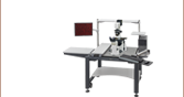
OTKB-FL
Fluorescence
Microscopy Module
(Optional Add-On)
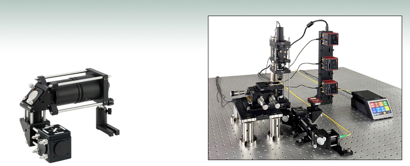
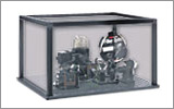
OTKB
Shown Assembled
on a Breadboard
(Not Included)


Please Wait
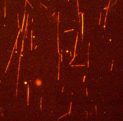
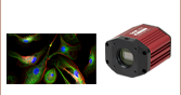
当社の光ピンセットと蛍光顕微鏡モジュールを組み合わせて取得したローダミンファロイジンで染色されたアクチンネットワークの蛍光イメージ(励起波長540 nm、発光波長565 nm)。(Nikon製プランフルオール(プランフルオリート)100X油浸対物レンズN100X-PFO、NA1.3を使用)。
特長
- 光ピンセットシステム一式
- In Vitroの医療・バイオ分野の実験に適した倒立型光学顕微鏡設計
- トラップ用のレーザ(976 nm、300 mW)は、タッチパネル式コントローラにて操作
- Nikon製100X油浸対物レンズ
- 内蔵型ピエゾアクチュエータ付き3軸の試料位置決めステージによるナノメートルレベルの分解能
- ビデオイメージング用CMOSカメラ(USBインターフェイス)
- 後方焦点面検出および蛍光顕微鏡モジュールが利用可能
当社のモジュール式光ピンセット(光トラップ)キットOTKB/Mにより、顕微鏡において微小な物質をトラップして操作をすることができます。 このレーザ光ピンセットは、すでに数多くの医療・バイオ分野の実験でお使いいただいています。医療・バイオ分野での光ピンセットの用途には、ウィルスやバクテリアのトラップ、細胞組織の操作、表面パターニング、分子モータやDNA、タンパク質などの生体分子の力学測定が挙げられます。 当社のピンセットを用いて行った実験の詳細データについては「ビデオ」および「関連出版物」のタブをご覧ください。 また、光ピンセットの機能についての詳細は「光ピンセット技術」タブをご覧ください。
当社のモジュール式光ピンセットは、研究実験に適した柔軟性を有しています。倒立型顕微鏡の設計がベースになっているので、標準的な試料に対応します。 ビデオ撮影用にCMOSカメラが付属しています。また、蛍光測定や単一分子測定などその他の顕微測定に対応させることも可能です。モジュール型システムの利点は、セッティングの追加などが可能な汎用性にあります。当社の標準部品で構築されているので、システムの改造、アップグレードも当社の他の標準部品と組み合わせて簡単に行っていただけます。
システムのモジュール性と構成
この光ピンセットシステムは予め部分的に組立てられたセグメントの状態で発送し、お手持ちの光学テーブルやブレッドボード上でシステムとして組立ていただく製品です。システムの組立て方とアライメントの方法は「ビデオ」タブでご覧いただけます。ベースシステムOTKB/Mに含まれる各セグメントと、別売りでご使用いただける光学コンポーネントの詳細については「システム」タブをご覧ください。このシステムには詳細な組立て手順が記載された取扱い説明書が付いています。
初期試験やアライメント用に必要な備品をセットにした光ピンセット用試料作製キットOTKBTK(下記参照)をご用意しておりますので、資料の準備や光ピンセットシステムが正しく組み立てられ機能するかどうかの確認にお使いいただけます。
別売りのモジュール
光ピンセットシステムOTKB/Mがブラックボックス型のシステムより優れている点の1つは、機能を追加するために光トラップの設計を簡単に変更できることです。例えば、後焦点面を検出するためのモジュールOTKBFMを、ベースキットOTKB/Mに簡単に取付けることができます。これにより、光トラップシステムOTKB/Mに、トラップ力、剛性、位置などの測定機能を追加できます。 モジュールOTKB-FL/Mを取付けると、光トラップに蛍光顕微鏡の機能を追加できます。これらのモジュールについての詳細は下記および「システム」タブをご覧ください。
標準品や蛍光モジュールの他にも、当社では特注品としてラマン分光法モジュールをご提供しています。光ピンセットにラマン分光法モジュールを追加する場合は、CREOL(The College of Optics & Photonics)での使用例をご参照ください:単一生体細胞の分子診断におけるマルチスペクトル光ピンセットの応用例。このモジュールに関する詳細な情報やお見積りをご希望の場合は当社までお問い合わせください。
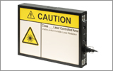
レーザの安全性について
レーザを動作させる際には、レーザの分類に留意し、適切な安全手順を守ることが必要です。 当社のモジュール式光ピンセットシステムでは、 976 nm、300 mWレーザを使用しています。 レーザ光の曝露の可能性があり、システムはClass 3Bに分類されます。 従いまして、レーザ保護メガネの使用を含む適切な安全手順を踏む必要があります。 レーザ分類システムおよび当社のレーザ用安全製品については、「レーザの安全性」タブをご覧ください。
| Item # | OTKB(/M)a |
|---|---|
| Tweezer Specifications | |
| Trap Force | ~10 pNb |
| Spot Size | 1.1 µm |
| Depth of Focus | 1 µm |
| Laser Wavelength | 976 nm |
| Max Power at Fiber Output | 300 mW |
| Objective Specificationsc | |
| Type | Nikon 100X Immersion Objective |
| Numerical Aperture | 1.25 |
| Input Aperture | Ø5 mm |
| Working Distance | 0.23 mm |
| Wavelength Range | 380 - 1100 nm |
| Recommended Cover Glass Thickness | 0.17 mm |
| Condenser Lens Specifications | |
| Type | Nikon 10X Air Condenser |
| Numerical Aperture | 0.25 |
| Working Distance | 7 mm |
| Wavelength Range | 380 - 1100 nm |
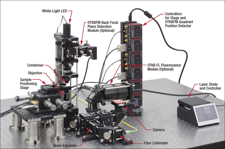
下のOTKB(/M)の写真の各モジュールをクリックすると、その詳細をご覧いただけます。
Click to Enlarge
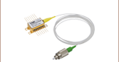
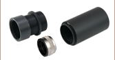
半導体レーザ用マウント
レーザ光の入射およびコリメート
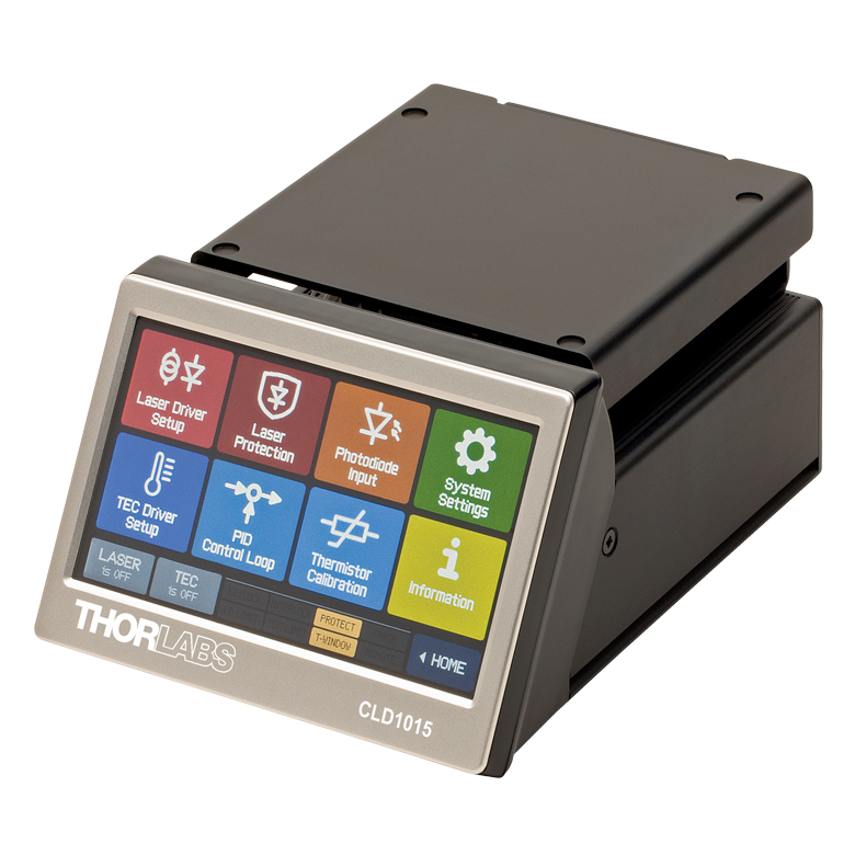
976 nmのトラップ用レーザ光源は、ファイバーブラッググレーティング(FBG)で安定化されたピグテール付きのシングルモード半導体レーザで、14ピンバタフライパッケージに封止されています。バタフライパッケージにはTEC素子とサーミスタが内蔵されているため、当社のTECおよびマウント付きコンパクトLDコントローラCLD1015を使用して、半導体レーザの温度を精密に制御できます。この半導体レーザ、マウント、およびコントローラの組み合わせは、レーザの出力パワーを十分に安定化できるように選択されたものですが、これはトラップ力を一定に保持するうえで重要です。入射光は当社のトリプレットファイバーコリメータを用いてコリメートすることで、高品質のビームが得られ、またアライメントも容易になります。
ビームエキスパンダ
このビームエキスパンダはガリレオ式エキスパンダをベースにしており、全体のスペースを最小限に抑えながらも倍率は3倍になっております。これには反射防止コーテイングが施されたアクロマティック複レンズ(型番ACN254-050-BおよびAC254-150-B)が使用されています。これらは、コリメートされたトラップ用レーザービームを拡大するために、コンピュータ設計によって無限共役比に最適化されています。このビームエキスパンダは、当社のケージシステムを用いてトラッピング光の広がりを最適化できるように構成されています。これによりトラップのZ位置を光軸に沿って最大12.5 mm調整することができます。
対物レンズおよびコンデンサーレンズ
OTKB/Mには、開口数(NA)1.25、倍率100倍のNikon製油浸対物レンズが付属します。このレンズは、レーザ光をスポットサイズ1.1 µmまで集光するのに使用します。その他、高い屈折率を有するポリスチレンビーズのトラップなどのアプリケーション用として、より大きなNA 1.3を有する対物レンズを下でご紹介しております。
試料を通過した光はコンデンサーレンズよってコリメートされます。このレンズはNA 0.25、倍率10倍のNikon製エアコンデンサーレンズです。
ステージ
サンプルステージは、3軸(X、Y、Z)移動ステージと、それに取り付けられた顕微鏡用スライドホルダMAX3SLHから構成されています。このステージはさらに移動用ブレッドボードに取り付けられており、それにより以下の機能が備わります。
- 移動用ブレッドボードTBB1515/Mを用いて、光路に対して直角方向に60 mmの移動が可能。これにより、試料の出し入れが容易になり、また試料をトラップの近くに置くことができます。
- 差動マイクロメータ付きNanoMaxシリーズステージMAX311D/Mを用いてX、Y、Z方向に4 mmの移動が可能。粗調整用ノブでは、1回転につき0.5 mm移動します。
- NanoMaxシリーズステージの差動ノブ(1回転につき50 µm移動)を用いて、X、Y、Z方向に300 µmの移動が可能。
- 3軸ステージのピエゾアクチュエータを用いて、X、Y、Z方向に20 µmの移動が可能。歪ゲージリーダは付いていませんが、OTKB/Mでは20 nmの分解能が得られます。内臓の位置決めフィードバック用歪ゲージセンサを使用すると、5 nmまでの分解能が得られます。トラップ力測定モジュールOTKBFMには2台のK-Cube™歪ゲージリーダ(KSG101)が付属しています。OTKB/Mには3台のピエゾアクチュエータが付属します。
カメラモジュールおよびLED光源
LED光源からの可視光が試料に照射され、その像はアクロマティック複レンズ(AC254-200-A-ML)を用いて、1440 x 1080ピクセルのカラーCMOSカメラ(CS165CU1)で画像化されます。赤外域フィルタが取り除かれた後であっても、光路中にあるショートパスフィルタとダイクロイックミラーにより、波長976 nmのレーザ光の後方散乱光によりCMOSセンサが飽和するのは防止されます。このカメラを使えば、カラーまたは白黒で、静止画と動画を取得できます。
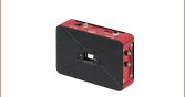
サンプルステージ用および別売りのトラップ力測定モジュールOTKBFM用のコントローラ
ステージ用およびトラップ力測定モジュールOTKBFM用のコントローラは、どちらもコンパクトなKinesis® K-Cubeシリーズの製品です。これらのコンパクトなコントローラ(60 mm x 60 mm x 47 mm)には、当社のUSBコントローラーハブが付いています。このハブは最大6個までのコントローラに電源を供給し、また1本のUSBケーブルでそれらを制御することができます。ハブはスペースに合わせて垂直(上の写真参照)にも水平にも取り付けることができます。
キットに付属している3台のピエゾアクチュエータ、およびトラップ力測定モジュールOTKBFMに付属している2台の歪ゲージリーダについての詳細は、それぞれステージおよびトラップ力測定モジュールの説明をご覧ください。
Click to Enlarge
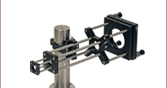
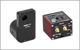
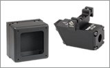
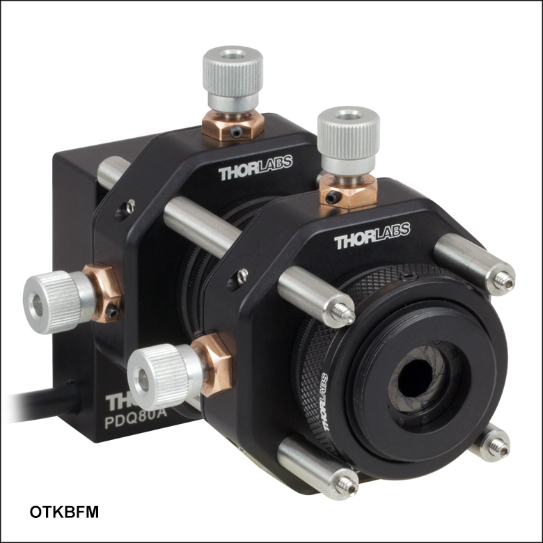
後方焦点面検出モジュールOTKBFMのコンポーネント:K-Cube 4分割PD位置ディテクタおよび歪みゲージリーダ(左)、 4分割PD位置ディテクタ付き光学モジュール(右)
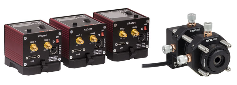
後方焦点面検出 & トラップ力測定モジュール
光ピンセット(光トラップ)のセットアップを定量的なトラップ力測定に使うには、トラップされた粒子の位置をモニタする必要があります。広帯域かつ高分解能で測定するために、4分割PD位置ディテクタ(QPD)をコンデンサーレンズの後方焦点面の共役面に配置することができます。この場合、QPDによって生成された信号はトラップされた粒子のトラップ中心からの相対的な位置変化に対して敏感に応答するため、粒子の位置、剛性、トラップ力などの測定に利用できます。別売りのモジュールOTKBFMには、モジュール式光ピンセットキットOTKB/Mに後方焦点面検出の機能を追加するためのQPD、オプトメカニクス部品、およびコントローラが含まれています。コントローラには、1台のK-Cube4分割PD位置ディテクターリーダKPA101と2台のK-Cube歪みゲージリーダKSG101 が含まれます。このモジュールには、データ取得(DAQ)用のハードウェアや、データを取得・分析するためのソフトウェアは付属しておりませんので、お手持ちのDAQ用ハードウェアや分析用ソフトウェアをご活用ください。
測定は振動に敏感なため、OTKBFMを含むシステムはアクティブ除振支柱付き光学テーブルに取り付けることをお勧めしています。
トラップ力測定および校正の方法に関する詳細は、「光ピンセット技術」タブをご参照ください。
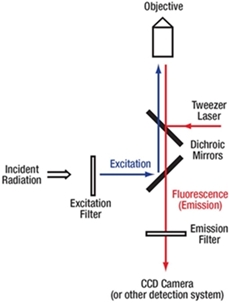
蛍光のビーム経路

Click to Enlarge
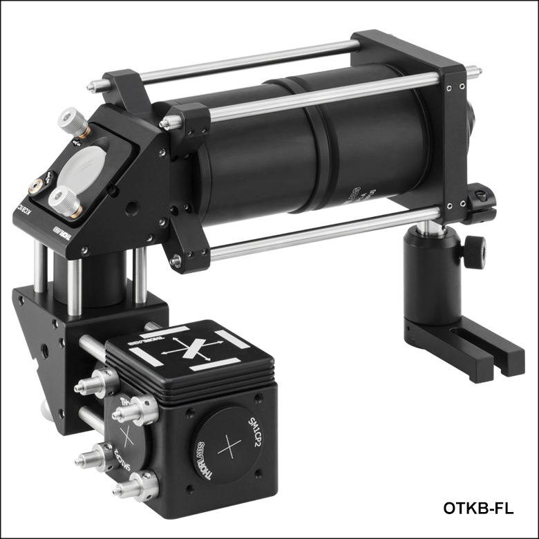
蛍光顕微鏡モジュールOTKB-FL(/M)
蛍光顕微鏡モジュール
蛍光顕微鏡を光ピンセット(光トラップ)と組み合わせることで、様々な試料の特性や細胞構造を視覚的に確認し、操作し、迅速に分析することができるようになります。この技術は、狭い空間に入ってきた単一分子の検出、細胞構造やバクテリアの立体構造変化の検出、単一DNA分子の弾性分析、大きな分子錯体の境界認識、加えられた力に対する個々の反応の計測などに用いることができます。当社では、右図のようなテスト済みの部品一式をモジュールとして提供しており、これを用いて光ピンセット(光トラップ)キットに蛍光顕微鏡の機能を追加することができます。
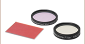
蛍光イメージングフィルタは、付属の蛍光フィルターキューブを用いて挿入・取り外しが簡単に行えます。蛍光体の選択の幅を広げるために、この蛍光モジュールにはイメージングフィルターセットを付属させておりません。当社では、様々な種類の標準的な蛍光体に対応する蛍光イメージングフィルタを別途ご用意しております。
また、RMS100X-PFOまたはN100X-PFOといったプランフルオリートやセミアポクロマート対物レンズも併せてご提供しています(下記参照)。プランフルオリートやセミアポクロマート対物レンズは、幅広い波長域を補正できるよう設計されているため、蛍光顕微鏡法に適しています。これらの対物レンズは、キットOTKB/Mに付属する標準的な対物レンズより大きな開口数を有し、一般的にプローブとして使用される官能化ポリスチレンのような粒子をトラップすることも可能です。
ここでは例として、均一にFITC染色された1.0 μmのポリスチレン製ビーズの入った溶剤を希釈したものを試料とし、励起光の波長は480 nm、蛍光の波長は520 nmである場合を考えてみましょう。励起光は、広帯域光源と励起フィルタMF475-35を組み合わせて発生させます。この励起フィルタの透過率は470~490 nmの波長範囲で85%を超えます。この励起光は、470~490 nmの波長範囲の光を反射し、508~675 nmの波長範囲の光を透過するダイクロイックミラーMD499によって、光ピンセットシステムに入射されます(右端の概略図をご覧ください)。標準的な落射蛍光技術と同様に、試料から発せられる蛍光は、反射された励起光と共に対物レンズで集光されるため、透過光検出法と比較して信号対雑音比が向上します。これらの光はダイクロイックミラー、さらに中心波長530 nm、FWHM帯域幅43 nmの吸収フィルタMF530-43を透過して、最後にCMOSカメラで検出されます。このCMOSカメラは、定量測定を行うためにフォトダイオードと置き換えたり、より高品質な蛍光イメージを得るためにサイエンティフィックカメラと置き換えたりすることができます。
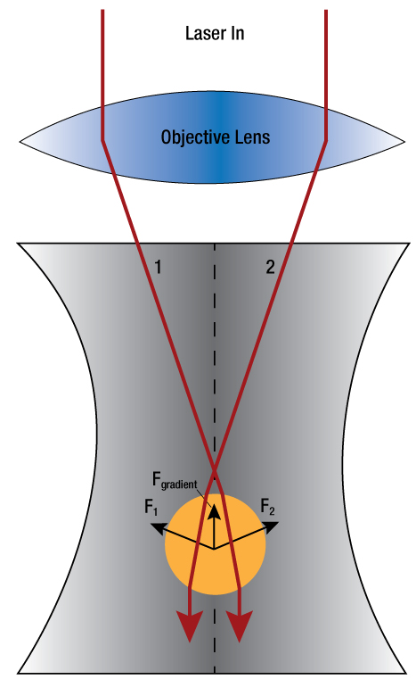
Click to Enlarge
集光されたレーザ光の中の粒子(光の波長よりも大きな粒子)に及ぼされる勾配力を図示しています。
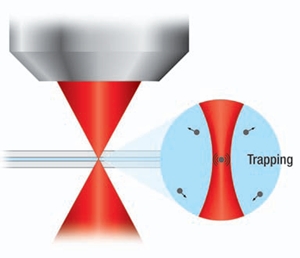
光ピンセットの基本原理
光ピンセットは光トラップとも呼ばれています。高い開口数の対物レンズを用いてレーザ光を極限まで集光すると、光子の散乱による運動量の伝達により、マイクロメートル程度の大きさの粒子をトラップする力が生じます。
1970年代の初めにArthur Ashkin氏が光トラップ力でマイクロメートル程度の大きさの誘電体粒子を水中で操作できることを証明しました(A. Ashkin. Phys. Rev. Lett. 24, 156 - 159 [1970]およびA. Ashkin et al. Opt. Lett. 1, No. 5, [1986])。 この技術により粒子を保持・操作することが可能になり、またフェムトニュートンまたはピコニュートンレベルのトラップ力が測定できるようになったため、光トラップはバイオエンジニアリングや、材料科学、物理学などの幅広い分野で重要なツールとなってきました。
粒子の大きさとトラップ波長の関係により、光トラップの理論を展開する際には2つの領域に分けて考える必要があります。 ミー散乱の領域では、トラップされる粒子の直径は光の波長よりもかなり大きく、トラップは光線光学の域内で説明できます。 光線は粒子を透過する際に屈折し、それがもたらす運動量の変化によって力が生じます。 粒子がレーザの光軸上にいない場合、ビーム中心により近い場所の光線が強いので、ビームの端に近い光線にくらべて、粒子により大きな運動量を伝達します。 このことで、粒子に対して、横方向の「勾配」力がビーム中心に向けて働きます。 粒子がレーザ光線の中心の位置に来れば、粒子内を屈折しながら進む光は対称形となり、その粒子は横方向ではトラップされます。
軸方向の力の動きはさらに複雑です。 粒子がレーザ光線の焦点に近い位置にあるとき、下図と右図にあるように、勾配力「Fgradient 」は焦点に向かって働きます。 さらに、光線が溶剤と粒子の界面で後方散乱するので、その散乱光が粒子に運動量を伝えることになり、光線の進行方向へ散乱力が働きます。 以上の2つの力を合わせると、全ポテンシャルはビーム集光部よりもわずかに下流にオフセットした場所で最小となります。 顕微鏡の像面で粒子をトラップするには、散乱力を補償するために、レーザ光の焦点は若干オフセットしている必要があります。
レイリー散乱の領域では、粒子の直径は波長よりもかなり小さくなり、光線光学は適用できなくなります。 この領域でのトラップ力を説明する時は、トラップされた粒子を点双極子であると考えます。 散乱力は光の吸収と再放射から生じ、勾配力はレーザ光の不均一場と粒子の誘起双極子との相互作用の結果として生じます(C. N. Keir and M. B. Steven. Review of Scientific Instruments 75, No. 9, 2004)。
波長に近い粒子サイズに対しては、ミー理論もレイリー理論も適用できないので、電磁気学的解釈はさらに複雑になります。 この理論を説明している論文は複数ありますが、下記が1例です:E. Almaas and I. Brevik. J. Opt. Soc. Am. B 12, 2429, 1995; J. P. Barton, J. Appl. Phys. 64, 1632 (1988); P. Zemanek et al. J. Opt. Soc. Am. A 19, 1025 (2002); K. F. Ren et al. Opt. Commun. 108, 343 (1994)。
光ピンセットによる力の測定
光ピンセットには粒子に加わる力を測定する機能があり、生体タンパク質などの細胞組織や分子モータを研究する上で有益なツールになっています。光ピンセットがトラップ用レーザ光の焦点に向けて粒子に加える力の大きさは、トラップ中心の近傍では粒子から焦点までの距離に比例します。レーザ光がトラップされた粒子を透過するときにその方向が変化(偏向)しますが、その大きさはトラップ中心から粒子までの距離に依存します。このことから、光ピンセットをフックの法則Fi = -kixiを用いてモデル化することができます。ここでkiはトラップ力(バネ)定数、xiは粒子のトラップ中心からの距離です。
さらに、レーザ光が試料面を通過すると、トラップされた粒子を透過した光とそれ以外の光との間に干渉が生じます。その結果、コンデンサの後焦点面における干渉パターンは、トラップ中心からトラップされた粒子までの距離に依存します。粒子によるレーザ光の偏向の大きさは4分割フォトダイオードによって電気信号に変換され、後焦点面での光の干渉を通じて粒子の位置に比例する電圧信号を生成します(F. Gittes and C. F. Schmidt. Opt. Lett. 23, No. 1, 1998)。
QPDで得られたデータは電圧で表示されます。トラップ力および位置を定量的に測定するには、ディテクタの応答特性(感度)を把握する必要があります。その1つの方法は、スタックビーズ(スライドガラスなどに固定されたビーズ)を移動してトラップを横断させ、その間のディテクタの出力電圧を記録します。移動させるサンプルステージのステップサイズは既知なので、ボルト単位で表された位置の信号をμmで表した位置情報に変換できます。ビーズがトラップを通過するとき、この信号はS字曲線を描きます。
正確にトラップ力を測定するには、トラップ力定数および粒子位置ディテクタの応答特性(感度)の精密な校正が求められます。このディテクタの応答特性(感度)は、レーザーパワーと粒子の性質によって変化します。トラップ力定数の値を求める一般的な方法には、パワースペクトル密度(PSD)ロールオフ法、等分配法およびストークスの抗力を用いる方法があります。
PSDロールオフ法では、トラップされた粒子のブラウン運動による位置の時間変化のパワースペクトル密度を計算します。これは、溶剤の粘度を既知とすると、それによるダンピングを含む調和振動子の応答と同じになり、以下の式で表されます。
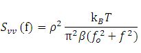
ここで、Svvは未校正のパワースペクトル、ρは線形電圧変位校正因子、kBはボルツマン定数、Tは媒質の温度、βは抵抗係数で、f0はコーナ(ロールオフ)周波数です。 PSD曲線のサンプルは右下のスクリーンショットをご覧ください。 PSDロールオフ法は、位置ディテクタの校正が正確かどうかを検出する方法として特に有効です。理由は、この方法は他の2つの方法のようにディテクタの応答特性(感度)に依存しないからです。
等分配法では、トラップされた粒子の平均的なポテンシャルエネルギと、溶剤中の分子の熱エネルギとが一致するとします。 この計算には、下中央のスクリーンショットに表示されている、トラップ力校正中に記録される時間ドメインデータを用います。 トラップ力定数kiは、計算式ki = kBT/[stddev(xi)]2を用いて決定されます。ここで、Tは絶対温度、stddev(xi)はxi座標における位置データの標準偏差です。
ストークスの方法では、様々な速度で試料を移動させます。 そこで粒子の粘性抵抗とトラップ力のバランスを計算します。 それぞれの方法は、異なる物理法則に基づいているので、校正を検証する際に組み合わせて利用すると便利です。
光ピンセット(光トラップ)キットの設置方法
動画では、光ピンセットキットOTKB(/M)のセットアップとアライメント方法について説明しています。なお、動画ではいくつかの旧製品が使用されていますが、キットにはマニュアルのShipping List(発送リスト)に記載されている現製品が同梱されています。
ナノ粒子のトラップ
Bergeron, J., Zehtabi-Oskuie, A., Ghaffari, S., Pang, Y., Gordon, R. Optical Trapping of Nanoparticles. J. Vis. Exp. (71), e4424, doi:10.3791/4424 (2013).
下のビデオでは、改良型のシステムOTKBを用いて20 nmのポリスチレンナノ粒子をトラップします。 ダブルナノホールの構造を利用することにより、トラップ力が大きくなるので、ナノメートルレベルの粒子のトラップが実現します。
光トラップ入門
下のビデオでは、MIT生物工学科、生体計測教育研究所のSteve Wasserman氏ならびにSteven Nagel氏が、光トラップの基礎と、モジュール型光ピンセットキットを用いて光トラップを較正する方法をご紹介しております。
当社の光ピンセット(光トラップ)キットOTKBを使用した研究ならびに教育について書かれた文献です。 当社の光ピンセットの活用方法については当社までご相談ください。
研究論文
Roder, P. B., Manandhar, S., Smith, B. E., Zhou, X., Shutthanandan, V. S. and Pauzauskie, P. J. Photothermal Superheating of Water with Ion-Implanted Silicon Nanowires. Advanced Optical Materials, 3, 1362, 2015.
Benjamin J. Gross and Mohamed Y. El-Naggar. A combined electrochemical and optical trapping platform for measuring single cell respiration rates at electrode interfaces. Rev. Sci. Instrum. 86, 064301, 2015
W. N. Wan Aziz, S. K. Ayop, and S. Riyanto. The Potential of Optical Tweezer (OT) for Viscoelastivity Measurement of Nanocellulose Solution. Jurnal Teknologi 74, 45, 2015.
Gusachenko, I.; Truong, V.G.; Frawley, M.C.; Nic Chormaic, S. Optical Nanofiber Integrated into Optical Tweezers for In Situ Fiber Probing and Optical Binding Studies. Photonics 2, 795, 2015.
Abhay Kotnala, Skyler Wheatona, and Reuven Gordon. Playing the notes of DNA with light: extremely high frequency nanomechanical oscillations. Nanoscale 7, 2295, 2015.
Skyler Wheaton, Ryan M. Gelfand, and Reuven Gordon. Probing the Raman-active acoustic vibrations of nanoparticles with extraordinary spectral resolution. Nature Photonics 9, 68, 2015.
Pick Chung Lau, Zhaozhao Zhu, Robert A. Norwood, Masud Mansuripur, and Nasser Peyghambarian. Thermally robust and blinking suppressed core/graded-shell CdSe/CdSe1−xSx/CdS 'giant' multishell semiconductor nanocrystals. Nanotechnology 24, 475705.
Kuan-Yu Chen, An-Ting Lee, Chia-Chun Hung, Jer-Shing Huang, and Ya-Tang Yang. Transoport and Trapping in Two-Dimensional Nanoscale Plasmonic Optical Lattice. Nano Lett 13, 4418, 2013.
Yuanjie Pang and Reuven Gordon. Optical Trapping of a Single Protien. Nano Lett 12, 402, 2012.
Corey Butler, Shima Fardad, Alex Sincore, Marie Vangheluwe, Matthieu Baudelet, and Martin Richardson. Multispectral optical tweezers for molecular diagnostics of single biological cells. Proc. SPIE 8225 82250C-1, 2012.
Ana Zehtabi-Oskuie, Jarrah Gerald Bergeron, and Reuven Gordon. Flow-dependent double-nanohole optical trapping of 20 nm polystyrene nanospheres. Scientific Reports 2, 966, 2012.
Yuhang Jin and Kenneth B. Crozier. An optical manometer-on-a-chip. Proc. SPIE 8097 80971U, 2011.
教育教材
Optical Tweezers. Abbe School of Photonics, Friedrich-Schiller-Universität, Physikalisch-Astronomische-Fakultät, 2010.
Aleksandra Radenovic. Optical Trapping. Advanced Bioengineering Methods Laboratory, École Polytechnique Fédérale de Lausanne.
D. C. Appleyard, K. Y. Vandermeulen, H. Lee, and M. J. Lang. Optical Trapping for Undergraduates. Am. J. Phys. 75 (1), January 2007.
レーザの安全性とクラス分類
レーザを取り扱う際には、安全に関わる器具や装置を適切に取扱い、使用することが重要です。ヒトの目は損傷しやすく、レーザ光のパワーレベルが非常に低い場合でも障害を引き起こします。当社では豊富な種類の安全に関わるアクセサリをご提供しており、そのような事故や負傷のリスクの低減にお使いいただけます。可視域から近赤外域のスペクトルでのレーザ発光がヒトの網膜に損傷を与えうるリスクは極めて高くなります。これはその帯域の光が目の角膜やレンズを透過し、レンズがレーザーエネルギを、網膜上に集束してしまうことがあるためです。
 |  |  |
 |  |  |
 |  |  |
安全な作業および安全に関わるアクセサリ
- クラス3または4のレーザを取り扱う場合は、必ずレーザ用保護メガネを装着してください。
- 当社では、レーザのクラスにかかわらず、安全上無視できないパワーレベルのレーザ光線を取り扱う場合は、ネジ回しなどの金属製の器具が偶然に光の方向を変えて再び目に入ってしまうこともあるので、レーザ用保護メガネを必ずご使用いただくようにお勧めしております。
- 特定の波長に対応するように設計されたレーザ保護眼鏡は、装着者を想定外のレーザ反射から保護するために、レーザ装置付近では常に装着してください。
- レーザ保護眼鏡には、保護機能が有効な波長範囲およびその帯域での最小光学濃度が刻印されています。
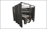
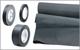
- レーザ保護カーテンやレーザー安全保護用布は実験室内での高エネルギーレーザの遮光にご使用いただけます。
- 遮光用マテリアルは、直接光と反射光の両方を実験装置の領域に封じ込めて外に逃しません。
- 当社の筺体システムは、その内部に光学セットアップを収納し、レーザ光を封じ込めて危険性を最小限に抑えます。
- ピグテール付き半導体レーザは、他のファイバに接続、もしくは他のファイバとの接続を外す際には、レーザ出力をOFFにしてください。パワーレベルが10 mW以上の場合には特にご注意ください。
- いかなるビーム光も、テーブルの範囲で終端させる必要があります。また、レーザ使用中には、研究室の扉は必ず閉じていなければなりません。
- レーザ光の高さは、目線の高さに設定しないでください。
- 実験は光学テーブル上で、全てのレーザービームが水平を保って直進するように設定してください。
- ビーム光路の近くで作業する人は、光を反射する不要な装飾品やアクセサリ(指輪、時計など)をはずしてください。
- レンズや他の光学装置が、入射光の一部を、前面や背面で反射する場合がありますのでご注意ください。
- あらゆる作業において、レーザは必要最小限のパワーで動作するようにご留意ください。
- アライメントは、可能な限りレーザの出力パワーを低減して作業を行ってください。
- ビームパワーを抑えるためにビームシャッタや フィルタをお使いください。
- レーザのセットアップの近くや実験室には、適切なレーザ標識やラベルを掲示してください。
- クラス3Rやクラス4のレーザ(安全確保用のインターロックが必要となるレーザーレベルの場合)で作業する場合は、警告灯をご用意ください。
- ビームトラップの代用品としてレーザービュワーカードを使用したりしないでください。
レーザ製品のクラス分け
レーザ製品は、目などの損傷を引き起こす可能性に基づいてクラス分けされています。国際電気標準会議(The International Electrotechnical Commission 「IEC」)は、電気、電子工学技術関連分野の国際規格の策定および普及を行う国際機関で、IEC60825-1は、レーザ製品の安全性を規定するIEC規格です。レーザ製品のクラス分けは下記の通りです
| Class | Description | Warning Label |
|---|---|---|
| 1 | ビーム内観察用の光学機器の使用を含む、通常の条件下での使用において、安全とみなされているクラス。このクラスのレーザ製品は、通常の使用範囲内では、人体被害を及ぼすエネルギーレベルのレーザを発光することがないので、最大許容露光量(MPE)を超えることはありません。このクラス1のレーザ製品には、筐体等を開かない限り、作業者がレーザに露光することがないような、完全に囲われた高出力レーザも含まれます。 |  |
| 1M | クラス1Mのレーザは、安全であるが、望遠鏡や顕微鏡と併用した場合は危険な製品になり得ます。この分類に入る製品からのレーザ光は、直径の大きな光や拡散光を発光し、ビーム径を小さくするために光を集束する光学素子やイメージング用の光学素子を使わない限り、通常はMPEを超えることはありません。しかし、光を再び集光した場合は被害が増大する可能性があるので、このクラスの製品であっても、別の分類となる場合があります。 |  |
| 2 | クラス2のレーザ製品は、その出力が最大1 mWの可視域での連続放射光に限定されます。瞬目反射によって露光が0.25秒までに制限されるので、安全と判断されるクラスです。このクラスの光は、可視域(400~700 nm)に限定されます。 |  |
| 2M | このクラスのレーザ製品のビーム光は、瞬目反射があるので、光学機器を通して見ない限り安全であると分類されています。このクラスは、レーザ光の半径が大きい場合や拡散光にも適用されます。 |  |
| 3R | クラス3Rのレーザ製品は、直接および鏡面反射の観察条件下で危険な可視光および不可視光を発生します。特にレンズ等の光学機器を使用しているときにビームを直接見ると、目が損傷を受ける可能性があります。ビーム内観察が行われなければ、このクラスのレーザ製品は安全とみなされます。このクラスでは、MPE値を超える場合がありますが、被害のリスクレベルが低いクラスです。可視域の連続光のレーザの出力パワーは、このレベルでは5 mWまでとされています。 |  |
| 3B | クラス3Bのレーザは、直接ビームを見た場合に危険なクラスです。拡散反射は通常は有害になることはありませんが、高出力のクラス3Bレーザを使用した場合、有害となる場合もあります。このクラスで装置を安全に操作するには、ビームを直接見る可能性のあるときにレーザ保護眼鏡を装着してください。このクラスのレーザ機器にはキースイッチと安全保護装置を設け、さらにレーザ安全表示を使用し、安全照明がONにならない限りレーザがONにならないようにすることが求められます。Class 3Bの上限に近いパワーを出力するレーザ製品は、やけどを引き起こすおそれもあります。 |  |
| 4 | このクラスのレーザは、皮膚と目の両方に損傷を与える場合があり、これは拡散反射光でも起こりうるとみなされています。このような被害は、ビームが間接的に当たった場合や非鏡面反射でも起こることがあり、艶消し面での反射でも発生することがあります。このレベルのレーザ機器は細心の注意を持って扱われる必要があります。さらに、可燃性の材質を発火させることもあるので、火災のリスクもあるレーザであるとみなされています。クラス4のレーザには、キースイッチと安全保護装置が必要です。 |  |
| 全てのクラス2以上のレーザ機器には、上記が規定する標識以外に、この三角の警告標識が表示されていなければいけません。 |  | |
| Posted Comments: | |
JANEESH George
(posted 2022-06-27 18:58:09.207) My research team and I want to know the technical possibilities and capabilities of modular optical tweezer system. We are interested in this system. But we need slight modifications. Can we arrange a meeting to discuss such things? cdolbashian
(posted 2022-07-01 11:20:24.0) Thank you for your interest in our OTKB system. We have reached out to you directly to discuss integration into your system. JANEESH George
(posted 2022-06-02 18:36:40.82) Our lab has already purchased Olympus FV 3000 confocal microscope. I would like to attach optical tweezer to that. Is that possible with modular optical tweezer system? Can I use 1064nm high power laser instead of 980nm? Chong Zu
(posted 2022-02-08 13:53:48.823) Hi! I am interested in getting an optical tweezer setup. And I am wondering if thorlabs provides an 1064nm trapping laser with larger power (>2W)? Thanks a lot! jdelia
(posted 2022-02-10 09:57:43.0) Thank you for contacting Thorlabs. The higher power option we have at 976nm, up to 0.9W is the BL976-PAG900. If the 1064nm and 2W is necessary for your application, you can source this externally to use with system. There are a few optics such as the triplet collimator and beam expander lenses you will need to replace in the system for optimal performance at 1064nm. I will follow-up with you via email to understand your application further. Joana Silvestre
(posted 2022-01-27 10:12:43.937) What is the reference for the four screws holding the inner ring of the dichroic base plate of the OTKB system? The screws are removed with a 1/16" (1.3 mm) hex key? Thanks you cdolbashian
(posted 2022-02-04 03:47:48.0) Thank you for reaching out to us with this inquiry. I have emailed you directly to verify exactly which components you are interested in identifying! Inês Carvalho
(posted 2021-05-30 15:18:57.2) Hello, could you please provide the dimension(diameter) of the back aperture of the condenser lens, CFI E Plan Achromat 10X, with reference MRP70100. Thanks for the attention. YLohia
(posted 2021-06-01 04:40:15.0) Hello, thank you for contacting Thorlabs. The MRP70100 is a Nikon objective. We called them and found that it has 10 mm diameter at the back aperture. romeric.pobre
(posted 2018-01-23 22:47:00.09) Hello, I plan to set up the OTKB/M with the optional galvo steering module. Before, I purchase the different modules, the picture in the galvo units are in-line with the fiberport collimator with the achromatic doublet lenses (AC254-060-B and AC254-150-B), but the fiberport collimator in the OTKB/M set up is coupled with ACN254-050-B and AC254-150-B) achromatic doublet lenses. Does it mean that I have to add another fiberport collimator for the galvo steering module or which achromatic doublets shall I use? Follow up question, do you have a particular DAQ card and installation guide you can recommend for the galvano steering module if I intend to use it for the dual optical trap? YLohia
(posted 2018-05-08 04:33:42.0) Hello, thank you for contacting Thorlabs. Unfortunately, we have had to stop production and sale of these OTKB galvo kits due to an incompatibility caused by a change in our galvo housing design and certain other parts that go in that kit. Our engineering team is currently working on a new design, but we are unable to provide a timeline for when these kits will be available again at the moment. To answer your other questions, you do not need another FiberPort collimator. We do not have any specific recommendations for a DAQ card -- the main thing here is the bandwidth and making sure that the DAQ card has enough of a bandwidth to support the scanning speeds of the galvo. henmarkovich
(posted 2017-08-31 19:11:42.937) Hello,
There is a problem in the manual of the OTKBFM-CAL:
In page 16 you describe the files that been saved by the system. In the ".LSdat" file description you are mentioning that the 4 columns are: Position in um and X,Y and SUM voltage. You also mention that the X and Y signals are normalized by the SUM.
The file itself, that saved by the system, is containing also 4 columns but the 1st and the 3rd are positions. And the 2nd and the 4th are voltage. (It makes much more sense).
My question is: is the voltage columns are normalized or they are just the pure readings from the detector?
I also recommend you to edit this paragraph in the manual, because it is clearly have a typo. tfrisch
(posted 2018-01-16 03:07:01.0) Hello, thank you for contacting Thorlabs. When you do a “Scan” on the software, the stage scans only one axis. Therefore it only saves the position of the axis being changed, plus all the signals from the detector. The first column would be the stage position in um (X or Y only at one time). The second and third columns are Xdiff and Ydiff (ratio between KPA101 outputs, and these are normalized). The fourth column is the sum of signal. I will reach out to you directly about your application and the dataset you have collected. ids33
(posted 2017-06-22 17:02:57.577) Hi there, I have your OTKB/M tweezer system and am now looking for ways of introducing a temperature controller. I was wondering whether you possibly have some products that could be connected/integrated into the NanoMax stage and thus enable doing temperature ramps. The temperature range I am looking for is at least between 10 and 70 degrees Celsius. I was thinking about making one on my own, but this is proving difficult due to the small working distances of the objective and the condenser. Any suggestions would be highly appreciated! tfrisch
(posted 2017-07-01 11:28:41.0) Hello, thank you for contacting Thorlabs. Temperature control will depend heavily on the sample. I will reach out to you directly about your applications and solutions we have for heating (and cooling) various samples. A heated lens tube would be the simplest place to start, though it lacks cooling.
https://www.thorlabs.com/newgrouppage9.cfm?objectgroup_id=1755 ids33
(posted 2016-12-21 11:35:37.523) Hi, is it possible to upgrade the modular optical tweezers to holographic ones using a reflective LCoS SLM without changing the setup too much? If yes, would you be able to suggest a possible way of doing that? tfrisch
(posted 2016-12-30 01:43:38.0) Hello, thank you for contacting Thorlabs. We will contact you directly about what components you need to integrate our SLM into your optical tweezer system. ysu
(posted 2016-06-17 16:18:44.37) Hello, I am very interested in this system. I am wondering whether a separate Laser for detecting the particle's position is needed. In your system, you seem to use the same Laser for both trapping and detecting. In my application, I worry about the accuracy of the position detected. Dose the spot size of the trapping light affect the detection accuracy? What is the limitation of the detection accuracy in your system? Thank you~ besembeson
(posted 2016-06-21 02:58:18.0) Response from Bweh at Thorlabs USA: The current design doesn't require a separate laser for detection as the trapping and detection is with the same IR laser through back focal plane interferometry. The sensitivity of the quadrant detector, the laser power level, characteristics of the bead being trapped and its medium will affect the accuracy of the system. With a separate detection laser such as one in the visible, overall bead position sensitivity and the range of particle detection will be improved. Also, faster trapped bead calibrations will be possible. We have not implemented such a separate detection beam design yet but this is possible to add to the system. l.yue
(posted 2015-02-19 19:23:10.68) Hello Sir,
We are very interested in this system. Could you provide a component list to me please?
By the way, can we purchase separate modules? Because we would like to use femtosecond laser as laser source to perform some experiments, is that okay? fs laser 800 nm, 100 fs, 1w.
Thank you very much.
Liyang besembeson
(posted 2015-02-25 08:38:33.0) Response from Bweh at Thorlabs USA: We have the component list in the manual at the following link: http://www.thorlabs.us/thorcat/19500/OTKB-Manual.pdf. You can also purchase separate modules as necessary for your application. The mirrors and lenses that are used in the standard configuration are not optimized for femtosecond sources but we have an extensive line of ultrafast optics that we can use as replacements for your application. I will follow up with you to further discuss your application. pagliusi
(posted 2014-09-09 17:17:27.967) I'm setting up the OTKB/M with the optional galvo module. According to the picture in the Catalog (pag 1825) the galvo units are in-line with the beam expander.
Does it mean that I should remove Mirror 1, or I can place it before mirror 1 (at 90deg and longer distance with respect to the beam expander) ? besembeson
(posted 2014-09-10 02:16:26.0) Response from Bweh: The galvo scanning cage cube should replace the right angle turning mirror. I will follow up with you by email for any further questions you might have. jzchen
(posted 2014-05-23 15:51:08.93) I am currently setting up the OTKB/M module and specifically mounting the laser diode. I am having trouble figuring up the correct setup of the mount and diode because I can not tell if the diode is a pump laser or a DFB laser? jlow
(posted 2014-05-28 08:03:29.0) Response from Jeremy at Thorlabs: The laser included in the OTKB is to be installed with the output fiber facing towards the Type 1 label which is printed on the mount of the laser controller CLD1015. We will send you a picture of the laser installed in the controller. We are also updating the manual to include this information in the future. Thank you for contacting us regarding this. moran5
(posted 2014-01-21 16:21:17.313) This uses an oil immersion 100X microscope objective. However it is operated as an inverted microscope. So how do you get oil between the microscope objective and the device under test? Inverted operation would have the oil drain away. Without oil the objective is abberated. How do you overcome this issue? besembeson
(posted 2014-01-22 01:12:40.0) Response from Bweh at Thorlabs: The objective that is used for trapping is mounted upright on the inverted microscope assembly and the oil drop when placed on top of the objective is viscous enough that it doesn't flow out. This way, the coverslip when lowered contacts the objective with the oil sandwiched. phygrk
(posted 2013-12-03 04:05:45.44) I have already purchased the optical tweezer.
Along with force calibration module.
Pl guide me for laser alignment.
Dr.G.R.Kulkarni
School of Basic Medical Sciences
University Of Pune
Pune411007
INDIA cdaly
(posted 2013-12-05 03:23:42.0) Response from Chris at Thorlabs: Thank you for your inquiry. We have a detailed description of the setup and alignment of the tweezer and force gauge module, which can be found in the manual here: http://www.thorlabs.com/thorcat/19500/OTKB-Manual.pdf. If you have further questions, please contact us directly at techsupport@thorlabs.com koreancarsg
(posted 2013-03-01 18:11:48.503) May i have a parts list of the tweezer kit? as we are planning to built a tweezer kit simliar but do our own customization. Hence would like to take referance from this. Thank u cdaly
(posted 2013-03-07 10:26:00.0) Response from Chris at Thorlabs: Thank you for using our feedback tool. In the OTKB manual linked next to the part number, we do have detailed descriptions of each of the 5 major groups of components in the system. I would suggest reading through the assembly instructions as well, where the products are called out and even labeled in accompanying images. tcohen
(posted 2012-05-23 10:02:00.0) Response from Tim at Thorlabs to Baohong: Thank you for your interest in our Optical Tweezers! This setup as is would not be suitable for trapping a microbubble. They have a lower refractive index compared to the surroundings and hence the focused beam will push the bubbles away instead. A donut shaped trap could be used, which means we would need to convert the Gaussian beam we use in our system to a Laguerre-Gaussian mode profile that will create such a focus. We don’t have such a module yet. Some people use diffractive optical elements to create such a beam. If the microbubble, however, is wrapped in a denser shell (some protein, lipid or similar) it may be possible to use this system. Due to the sensitivity of the measurements, we usually recommend an active isolation support for mounting this system and we have updated the OTKBFM page to address this point. baohong
(posted 2012-05-19 21:03:27.0) I am very interesting in this optical tweezers. Here are two questions and hope you can help.
1) can this system be used to trap a microbubble (1-5 microns in diameter)? or is there any module that can be attached to trap a microbubble?
2) Is there any requriment for the optical table to hold this optical tweezer system? For example, I have an optical table from thorlabs (PTQ11109 with the legs of PTH603). This is a passive optical table. Do you think it is good enough (based on isolation of vibration and other parameters) for holding this optical tweezer system?
thanks
baohong bdada
(posted 2011-12-13 13:40:00.0) Response from Buki at Thorlabs:
Thank you for your interest in collaborating with Thorlabs. A member of our marketing team will contact you shortly. gspaldin
(posted 2011-12-12 15:40:19.0) To Alex Cable:
What I want is to identify friendly folks in high places who might help us ( www.advlab.org ) to coordinate support for an endowment for the kinds of initiatives ALPhA / AAPT seeks to deliver:
There's no doubt that ALPhA is off to a good start (e.g., our offerings sell out, the 2009 ALTC was a big hit, so far we've filled 100 ALPhA Immersion slots with faculty/staff from around the nation, and I've now delivered 120 ALPhA single-photon detectors to a wide variety of institutions), but we've clearly reached a point where we are severely constrained by the lack of an endowment. -- We need to establish a fund to allow us to move ahead with planning key initiatives.
What we need is to find the right foundation or set of vendors to partner with us in establishing an endowment that will help keep up moving forward. Suggestions would be greatly appreciated.
Gabe Spalding
2012 Chair, Conference on laboratory instruction Beyond the First Year of college
Past-President of ALPhA (Advanced Laboratory Physics Association)
Chair of the national AAPT Committee on Laboratories
Professor of Physics, Illinois Wesleyan University
Office: (309) 556-3004, Cell: (309) 660-1222
http://titan.iwu.edu/~gspaldin lara
(posted 2010-12-06 05:18:41.0) Im interested in OTKB/M with the Force Measurement Module. I read that their total price is €17.047,00, but I would have a final quotation including also the steering option and the three addtional software.
Thanks a lot. Best Regards. Lara Selvaggi Thorlabs
(posted 2010-08-25 18:16:53.0) Response from Javier at Thorlabs to amoyer: Thank you for your feedback. The laser used in the OTKB kit can be classified as Class 1 when the trap is functional, since the laser is almost completely enclosed (except for the output from the microscope objective, which is divergent). Also, only a fraction of the full output of the laser is necessary for trapping particles. However, since the laser can output up to about 330 mW, the appropriate classification is 3B. Proper care and safety procedures must be followed. The laser control electronics are equipped with a key switch and interlock mechanism to comply with this classification. Also, it is recommended to wear eyewear and use warning labels/signs. I will send you links for these. You can also find helpful information about laser hazards through the following link: http://www.osha.gov/SLTC/laserhazards/ amoyer
(posted 2010-08-25 11:37:08.0) The University is in the process of purchasing this product. As the EHS Associate for the University, I am in need of the safety procedures that are needed to operate this equipment.
Signage: Danger Laser correct?
Do we need to install a lighted warning sign activated when the laser is energized with a fail safe interlock?
The MPE (maximum Permissible Exposure)
The NHZ (Nominal Hazard Zone)
The Optical Density.
Thank you for your help jens
(posted 2009-10-17 07:41:25.0) A reply from Jens at Thorlabs: yes, we can certainly quote any subset of components from the kit, so for example the force measurement module plus the condenser and holder. PLease take into account however that the force measurement module is meant to be used with the base system (OTKB) since the force module includes strain gauge controllers which connect to the MAX311 stage which is part of the main system. We will contact you with a quotation shortly. ee4243
(posted 2009-10-16 23:55:29.0) Is this include "force measurement module"?
If not, I would like to know how much is it?
I would like to have a quote with it, if possible. jens
(posted 2009-07-31 18:17:13.0) A reply from Jens at Thorlabs: the holder for the condenser and the Nikon optics are part of the kit. So if you order the part number OTKB you will get those items with the delivery. xbyin
(posted 2009-07-31 17:44:56.0) Dear sir,
I am interested in this product. However, how do I get the nikon condenser and the conderser holder,
CDI4391 and LCP03-1.45CH-SP? thanks,
xb |

 ズーム
ズーム光ピンセット(光トラップ)のセットアップを定量的なトラップ力測定に使うには、トラップされた粒子の位置をモニタする必要があります。広帯域かつ高分解能で測定するために、4分割PD位置ディテクタ(QPD)をコンデンサーレンズの後方焦点面の共役面に配置することができます。この場合、QPDによって生成された信号はトラップされた粒子のトラップ中心からの相対的な位置変化に対して敏感に応答するため、粒子の位置、剛性、トラップ力などの測定に利用できます。別売りのモジュールOTKBFMには、モジュール式光ピンセットキットOTKB/Mに後方焦点面検出の機能を追加するためのQPD、オプトメカニクス部品、コントローラが含まれています。このモジュールには、データ取得(DAQ)用のハードウェアや、データを取得・分析するためのソフトウェアは付属しておりませんので、お手持ちのDAQ用ハードウェアや分析用ソフトウェアをご活用ください。
この測定は振動に敏感なため、OTKBFMを含むシステムはアクティブ除振支柱付き光学テーブルに取り付けることをお勧めしています。
トラップ力測定および校正の方法に関する詳細は「光ピンセット技術」タブをご参照ください。

 ズーム
ズーム蛍光顕微鏡を光ピンセット(光トラップ)と組み合わせることで、様々な試料の特性や細胞構造を視覚的に確認し、操作し、迅速に分析することができるようになります。 この技術を用いれば、狭い領域に僅かに1個の分子が入ってきた場合でも検知可能で、細胞やバクテリアの立体構造変化の検知や1つのDNAの弾性分析が行なえるだけではなく、大きな分子錯体の境界を認識して、力を加えた際の個々の反応も計測できます。 当社では、光ピンセットキットにこうした機能を追加できる蛍光顕微鏡モジュールをご用意しております。
蛍光イメージングフィルタは、付属の蛍光フィルターケージキューブを用いて挿入・取り外しが簡単に行えます。 蛍光体を選択いただく際の幅が広がるよう、イメージングフィルターセットはこの蛍光モジュールに付属しておりません。当社では、様々な種類の標準的な蛍光体に対応する蛍光イメージングフィルタ を別途追加でお買い求めいただけます。
また、RMS100X-PFOやN100X-PFOといったプランフルオール(プランフルオリート)やセミアポクロマート対物レンズも併せてご提供しています(下記参照)。 プランフルオールやセミアポクロマート対物レンズは、幅広い波長域を補正できるよう設計されているため、蛍光顕微鏡法に適しています。 これらの対物レンズは、キットOTKBに付属する標準的な対物レンズより高い開口数を有し、一般的にプローブとして使用される官能化ポリスチレンのような粒子をトラップすることが可能です。
OTKB-FL/Mは、標準仕様では光源は付属しません(お手持ちの光源をご利用いただくことを想定しています)。 液体ライトガイド用のØ3 mmのレセプタクルは付属しています。
その他の用途については、「システム」タブ内の蛍光顕微鏡モジュールの説明をご参照ください。

 ズーム
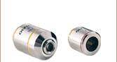
ズーム- RMS100X-PFOはNA 1.30のOlympus社製対物レンズ
- N100X-PFOはNA 1.30のNikon社製対物レンズ
ポリスチレンビーズなど高い屈折率を有する物質の光トラップや光マニピュレートする用途では、光ピンセットキットOTKB/Mに標準品として含まれているNA 1.25の対物レンズよりも開口数が高いプランフルオール(プランフルオリート)またはセミアポクロマート対物レンズをお勧めしています。 NA値の高い対物レンズにより、単一粒子の分光が可能になります。例としては、ポリスチレン製プローブビーズをトラップした状態で、トラップされているビーズからの蛍光を励起しながら観察する用途があります。
*価格について - こちらの製品は新設研究室サポートプログラムをはじめとするすべてのお値引きの対象外となります。予めご了承ください。

 ズーム
ズーム
- 光ピンセットキットとの併用に適した製品
- 寸法: 101.6 mm x 68.6 mm x 12.7 mm
顕微鏡用スライドホルダMAX3SLHを使用することによって、モーションコントロールステージにペトリ皿やガラス製のスライドを取付けることができ、光ピンセットOTKB/Mのような顕微鏡セットアップと組み合わせて使用することができます。 4つのM3ザグリ穴が1セットとM6のスロットが1セットあるので、様々なスライドが取り付けられます。 回転するバネクリップにより、ペトリ皿とガラス製スライドの取り換えが簡単に行えます。

 ズーム
ズーム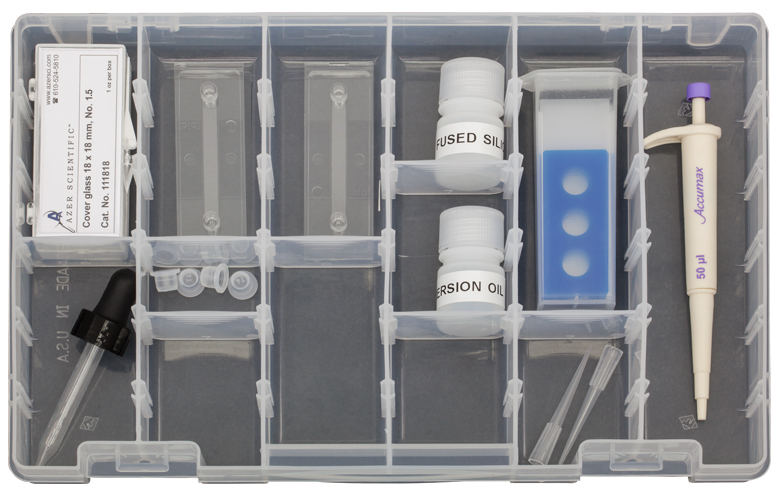
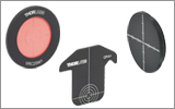
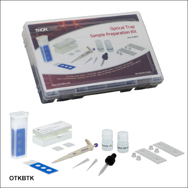
OTKBTKは、当社の光ピンセットキットOTKB/M、ポータブル光ピンセット教育用キットEDU-OT3/Mと共にお使いいただけるよう設計されています。 光ピンセットをお使いいただく際、試料の準備や、光トラップの試験などにお使いいただくと便利です。 キット内容は下記の通りです。
- 顕微鏡用の不乾性液浸油、Cargille Type LDF
- EDU-OT3/Mでは使用しません。
- 脱イオン化された水に入った非機能化溶融石英ビーズ:Ø2.06 µm、2 g/ml
- 容量が50 µLのミニピペット
- 溝付きのプラスチック製スライド2枚:高さ400 µm、容量100 µL
- ウェル付き顕微鏡用スライドガラス5枚、Ø10 mm、厚さ20 µm
- カバーガラス100枚、18 mm x 18 mm、厚さ No.1.5
- 油浸用のスポイト
※在庫について:本製品は保存期限があるため、受注生産となっております。ご入用の際には、sales@thorlabs.jp までお問い合わせください。