 Products Home
位置センシングディテクター(PSD)用オートアライナーKinesis® K-Cube™
- Enables Auto Alignment in Closed-Loop Mode
- Provides Position Measurement in Open-Loop Mode
- Operation via Local Panel Controls or Remote PC via USB
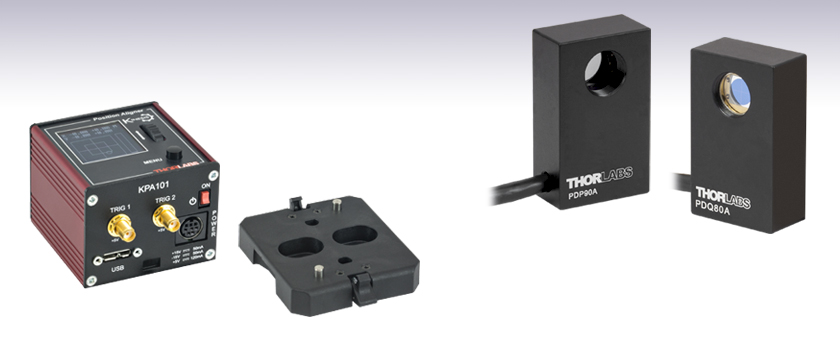
KPA101
Power Supply
Sold Separately
PDP90A
2D Lateral
Effect PSD
PDQ80A
Segmented
Quadrant PSD
Detectors
Available Separately
Table Mounting Plate
(Included with KPA101)


Please Wait
| Item # | KPA101 |
|---|---|
| X & Y Difference Outputs | -10 to 10 V, SMA Connectors |
| Sum Output | 0 to 10 V, SMA Connector |
| Position-Sensing Detector Input | 6-Pin Hirose Connectora |
| Closed-Loop Bandwidth | Up to 1 kHzb |
| Open-Loop Bandwidth (-3.0 dB) | 100 kHz |
| USB Connector Type | USB 3.0 |
| USB Connection Speed | USB 1.1 Full Speed (12 Mbps) |
| Dimensions (W x D x H) | 60.0 mm x 60.0 mm x 49.2 mm (2.36" x 2.36" x 1.94") |
Click to Enlarge
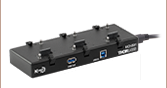
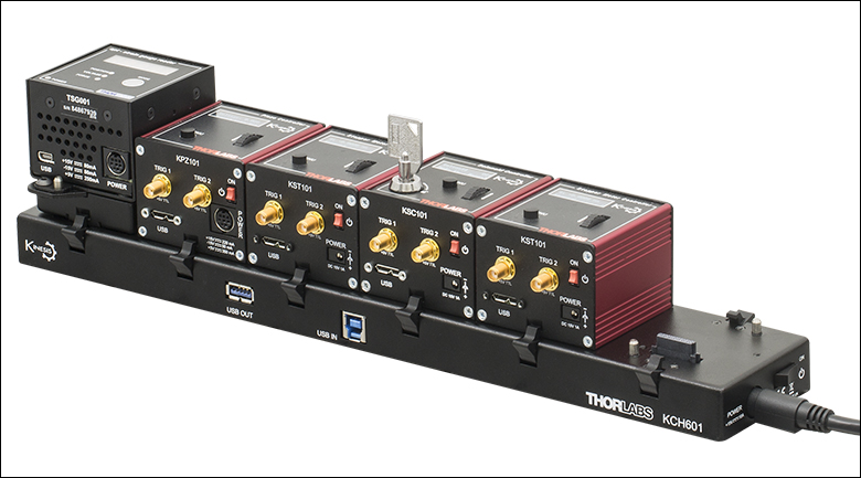
K-CubeならびにT-Cubeモジュールを取り付けたUSBコントローラーハブKCH601。T-CubeはアダプタープレートKAP101を使用してハブに取り付けています。
特長
- コンパクトな設置サイズ:60.0 mm x 60.0 mm x 49.2 mm
- 閉ループモードでのセンサ中心へのビームの自動アライメント
- 開ループモードでのビーム位置測定
- ユニット上でのフル制御が可能な有機EL(OLED)メニューおよび位置ディスプレイ
- 和信号、差信号、およびフィードバック信号の電圧出力
- Kinesis®またはAPT™制御用ソフトウェア一式(詳細は「モーションコントロールソフトウェア」のタブをご覧ください)
- ソフトウェアは他のKinesisならびにAPTコントローラにも対応しており、統合システムの開発が可能
- 現在のモデルに加えて、旧モデルのT-Cube™コントローラにも対応
- 電源は別売り
- USBコントローラーハブ(別売り)による多軸拡張も可能
- 磁石と固定用クリップの付いた光学テーブル取付け用アダプタが付属
K-Cube™ビーム位置調整用アライナKPA101は、当社の新しいKinesis®シリーズのコンパクトな高性能コントローラです。4分割位置センサよびラテラル効果位置センサーヘッド(詳細は「一般的な用途」タブをご覧ください)に接続して、センサ上のビーム位置を測定したり(開ループモード)、自動ビームステアリング素子用の入力信号を生成したり(閉ループモード)するためにお使いいただけます。 K-CubeピエゾドライバKPZ101と組み合わせると、そのような閉ループビームステアリングの用途に適したものになります。KPA101を他社製のセンサと一緒に使う方法に関しては、当社までお問い合わせください。
内蔵のソフトウェアにより、ユニット上のメニューボタン、有機EL(OLED)ディスプレイ、制御ホイール、外部トリガ信号のいずれかを使用して位置センシングディテクタ(PSD)との通信が可能です。 ユニット上での制御に加え、USB接続によりPCで容易に操作することもできます。そのために、当社では新しいKinesisソフトウェアパッケージと従来のAPT(Advanced Positioning Technology)ソフトウェアパッケージの2種類をご用意しております。
Kinesisソフトウェアでは.NETコントロールが使用でき、最新のC#、C++、Matlab、LabWindows/CVI、Visual Basic、LabVIEW™、その他.NET対応言語を使用する開発者がカスタムプログラムを作成することもできます。当社の従来のAPTソフトウェアを使用した場合は、ActiveX®プログラミング環境を利用して複雑な動作シーケンスを素早く設定できます。例えば、当社のステージおよびアクチュエータの動作に関連するあらゆるパラメータはこのソフトウェアによって自動的に設定されます。2つのソフトウェアパッケージの詳細については、「モーションコントロールソフトウェア」、「Kinesisチュートリアル」ならびに「APTチュートリアル」タブをご覧ください。
ユニットの設置面積は60.0 mm x 60.0 mm x 49.2 mmと非常にコンパクトで、上面パネルのコントローラを使用する際にシステムの近くに配置できるのも便利な点です。テーブル上で操作できれば駆動ケーブルの長さが短くなり、ケーブルの管理も楽になります。ユニットの前面には電源スイッチが付いており、このスイッチをオフにすると全てのユーザ設定が保存されます。ユニットの電源を切るときには、必ずこのスイッチをオフにするようにしてください。KPA101には長さ1.5 mのA-MicroBタイプのUSB 3.0ケーブルが1本付属します。
光学テーブル取付け用プレート
各ユニットには、モジュールのベース部分をクリップで固定できる取付けプレートが付属します。プレートには2つの磁石が付いており、光学テーブルに一時的に設置する際にご使用いただけます。また、恒久的な取り付けに使用できるM6キャップスクリュ用ザグリ穴も2つ付いています。プレートの取付け方法については「取付けオプション」タブをご参照ください。
電源の選択
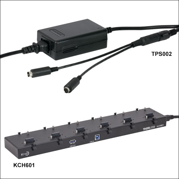
K-Cube KPA101には電源が付属しませんが、電源TPS002を使用することができます。電源TPS002は標準的な壁コンセントに差し込むことができ、最大2台のK-CubeまたはT-Cubeに+15、-15、+5 VDCの電源を供給します。
KPA101は、USBコントローラーハブKCH301、KCH601にも対応しています。USBコントローラーハブは1つのUSB接続によりハブに繋がっているすべてのK-CubeならびにT-Cubeを制御可能とします。 また、KPA101をK-CubeピエゾドライバKPZ101などのビームステアリングコントローラと組み合せて閉ループモードで使用する場合、ハブで接続されていればCube同士で直接通信できるので便利です。この結果、閉ループモードで動作しているKPA101が生成するフィードバック信号を、ビームステアリング素子を駆動するピエゾコントローラKPZ101へ直接送ることが可能になります。
| Detectors and Sensors | ||
|---|---|---|
| K-Cube Beam Position Aligner | Lateral Effect Position Sensor | Quadrant Position Detectors |
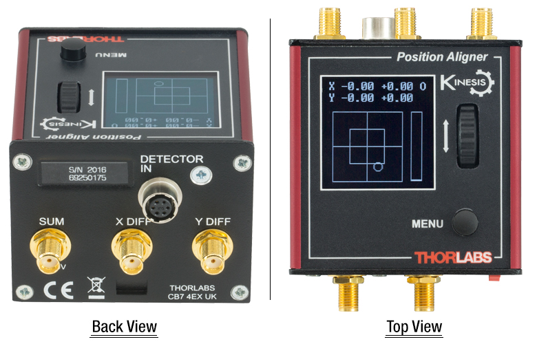
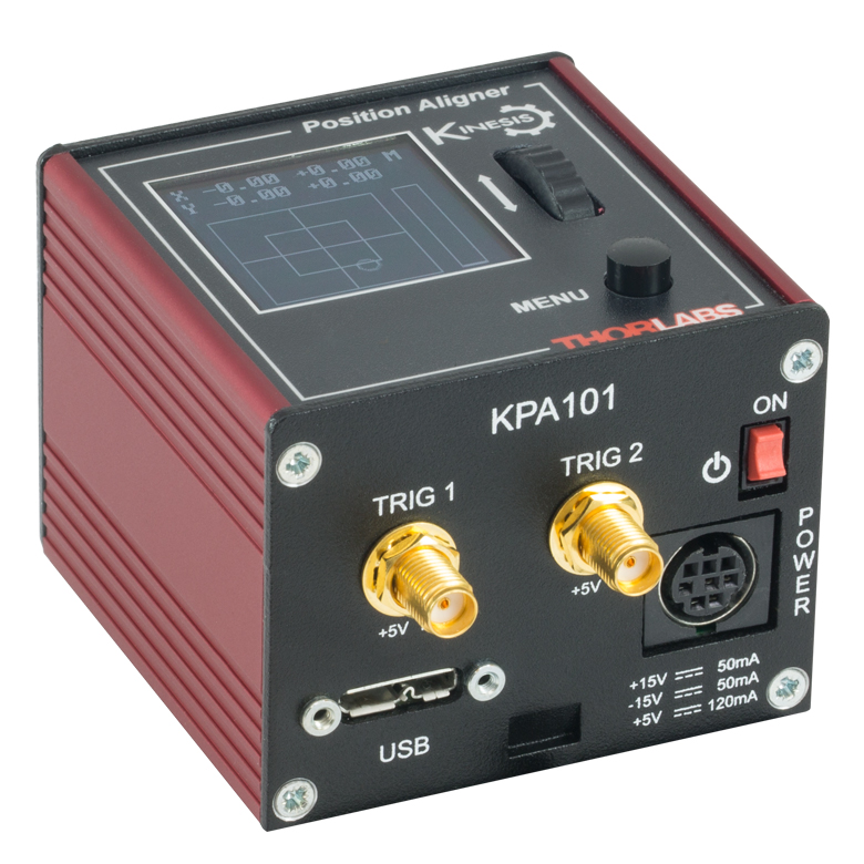
SUM、LV OUT X DIFF&LV OUT Y DIFFSMAメス型 | TRIG 1SMAメス型 | TRIG 2SMAメス型 |
 | | |
コネクタからの3種類の出力信号:ディテクタに当たった全光量(SUM)に比例した信号、X軸アライメント用の[左の光量-右の光量](LV OUT XDIFF)の信号、およびY軸アライメント用の[上の光量-下の光量](LV OUT YDIFF)の信号。 | +5 V TTL | +5 V TTL |
これらのコネクタからは5 Vのロジックレベルの信号を入出力します。トリガ信号を外部機器に出力する、あるいは外部機器から入力するかについては設定することができます。ロジックレベルの調整や、トリガ信号の入力あるいは出力の設定は、それぞれのポートごとに独立に行うことが可能です。 | ||
電源コネクタ
ミニDINメス型
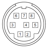
| Pin | Description | Pin | Description |
|---|---|---|---|
| 1 | +5 V (120 mA Max) | 6 | Common Ground |
| 2 | +5 V (120 mA Max) | 7 | Common Ground |
| 3 | -15 V (50 mA Max) | 8 | Common Ground |
| 4 | +15 V (50 mA Max) | Shield | Common Ground |
| 5 | +5 V (120 mA Max) |
PC接続用コネクタ*
*このUSBポートはUSB3.0対応ですが、USB2.0でもご使用いただけます。USB 2.0 を使用する際は、Micro-Bタイプコネクタを上図の網掛け部分に接続します。KPA101にはAタイプ-MicroBタイプのUSB 3.0ケーブルが1本付属します。
K-Cube™取付けオプション
K-Cube™コントローラの光学テーブルへの固定方法を2種類ご用意しております。1つは光学テーブル取付けプレートで、すべてのK-Cubeに付属しており、1台のコントローラを光学テーブルに取り付けることができます。もう1つは、3ポートあるいは6ポートのUSBコントローラーハブ(別売り)で、当社のK-Cubeコントローラを取り付け、それらに電力を供給することができます。詳細は下記をご覧ください。
光学テーブル取付けプレート
各ユニットには、コントローラのベース部分をクリップで固定できる取付けプレートが付属します(下の動画参照)。プレートには2つの磁石が付いており、光学テーブルに一時的に設置する際にご使用いただけます。また、2つのM6キャップスクリュ用ザグリ穴は、恒久的に取り付ける際にご使用ください。光学テーブル取付けプレートの図面は「仕様」タブでご覧いただけます。
Kinesis USBコントローラーハブ
USBコントローラーハブKCH301やKCH601を用いると、複数のユニットを取り付けて、それらを1台のPCに接続することができます。 コントローラーハブは、3台(KCH301)もしくは6台(KCH601)のK-CubeやT-Cubeをサポートするハブ部分と、壁コンセントに接続して電力を供給する電源部分から構成されています。K-Cubeはユニットについているクリップで簡単にハブに取り付けられますが、T-Cube(現製品および旧製品)の取り付けには、下の動画のようにアダプタープレートKAP101が必要です。 複数のコントローラをお使いになるときには、ハブをご使用になるとUSB用と電源用のケーブル本数を大幅に削減することができます。
K-Cube用光学テーブル取付けプレート
T-Cubeと違い、すべてのK-Cubeには、コントローラのベース部分をクリップで固定できる取付けプレートが付属します。プレートには2つの磁石が付いており、光学テーブルに一時的に設置する際にご使用いただけます。また、2つのM6キャップスクリュ用ザグリ穴は、恒久的に取り付ける際にご使用ください。
Kinesis USBコントローラーハブ
3ポートまたは6ポートのUSBコントローラーハブを用いると、多軸の操作をする際に複数のコントローラを1台のPCに接続することができます。K-Cubeはハブに直接取り付けられますが、T-Cubeの取り付けにはアダプタープレートKAP101が必要です。
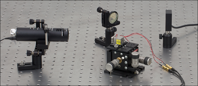
典型的な自動アライメントシステムのセットアップ
自動アライメントシステムのセットアップ例
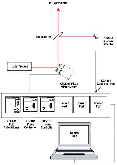
右は基本的な自動アライメントシステムのセットアップ例です。フォトダイオードセンサPDQ80A、ビーム位置調整用アライナKPA101、2台のピエゾドライバKPZ101、ピエゾ駆動の2軸ミラーマウントASM003(旧製品、代替品はこちらからご覧いただけます)、レーザ光源、PCで構成されています。このシステムは、レーザ光のパワー密度に基づいてレーザビームがディテクタアレイの中心にくるように位置決めを行い、その位置を保持するのに用いられます。
Click to Enlarge
自動アライメントシステムのセットアップ例
上の写真にある実験セットアップは、右の図に基づいて作られています。レーザ光源としては波長635 nmの赤色半導体ーザーモジュールLDM635が用いられています。レーザ光はフレクシャーステージMBT616Dに取り付けられた90°偏向ミラーミラーマウントASM003(旧製品、写真中央)に入射します。90°偏向ミラーのX軸とY軸は、2台のピエゾアクチュエータKPZ101(写真には表示されていません)で制御されます。なお、ピエゾ素子によるビームのアライメント調整は、小さな範囲に限られる点にご留意ください。90°偏向ミラーにより光をペリクルビームスプリッタBP150の方向に反射されます。このビームスプリッタを透過した光は実験セットアップ(写真には写っていません)の方向に伝搬します。一方、反射した光はオートアライナKPA101(写真には写っていません)で制御される4分割位置センサPDQ80A(写真の右端)に向かいます。
旧世代のT-Cube TPZ001よりも前の世代のT-Cube(「Rev. 1」などのように、T-Cubeが起動したときに改訂番号がLED画面上に表示されます)と組み合わせて使用する場合は、コントローラーハブKCH301やKCH601、あるいは旧世代のTCH002を使用する場合でも、T-Cubeは2つの外部SMAコネクタを使ってビーム位置調整用アライナに接続する必要があります。K-Cube™ KPZ101またはT-Cube Rev. 2 TPZ001をコントローラーハブと組み合わせて使用する場合は、SMA-SMAケーブルは必要ありません。
| K-Cube vs. T-Cube Feature Comparison | ||
|---|---|---|
| Feature | KPA101 K-Cube | TPA101 T-Cube |
| Kinesis Software Compatibility | ||
| APT Software Compatibility | ||
| Kinesis USB Controller Hubs Compatibility | Requires KAP101 Adapter | |
| TCH002 T-Cube USB Controller Hubs Compatibility | N/A | |
| OLED Position Display | N/A | |
| Power Switch | N/A | |
| Bidirectional SMA Trigger Porta | 2 | N/A |
| SMA SUM, X Diff, and Y Diffa | ||
| Computer Connectiona | USB 3.0 Micro B (USB 2.0 Compliant) | USB 2.0 Micro B (USB 2.0 Compliant) |
| Included Mounting Plate | ||
| Size (L x W x H) | 60.0 mm x 60.0 mm x 49.2 mm (2.36" x 2.36" x 1.94") | 60.0 mm x 60.0 mm x 49.2 mm (2.36" x 2.36" x 1.94") |
| On-Unit Menu | ||
| Open Loop Mode | ||
| Closed Loop Mode | ||
| Monitor Mode | ||
| Automatic Loop Switching | N/A | |
| Screen Brightness | N/A | |
Kinesis®モーションコントローラのご紹介
旧世代のT-Cube製品から大幅に改良されたK-Cubeのラインナップでは、新しいKinesisソフトウェアの導入だけでなく、物理的設計やファームウェアの全面的な見直しも行い、汎用性を高めています。
すべてのK-Cubeコントローラにはデジタルディスプレイが付いています。KPA101の有機ELディスプレイは基本的な入出力情報の表示を行うだけでなく、モニタ、閉ループ、開ループ、閉/開ループの自動切換えなどを含む様々なメニューが選択可能です。ユニットのホイールとメニューボタンにより、利用可能な機能がスクロールできます。またユニットの前面には電源スイッチが付いており、オフにすると、双方向性があり、5 V TTLロジック信号を入出力する2つのSMAトリガーポートの設定を含むすべての調整可能な設定が保存されます。
K-Cube PSD用コントローラKPA101と旧世代T-Cube TPA101の機能の全比較については右の表をご覧ください。
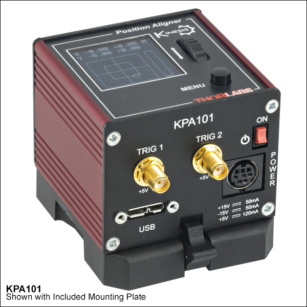
Click to Enlarge
K-Cube Kinesis PSD用コントローラKPA101
Kinesis USBコントローラーハブ
Kinesis USB 2.0コントローラーハブは、K-Cubeコントローラの機能を補完する製品です。USBハブには3台用と6台用の2種類があり、複数のK-CubeやT-CubeのコントローラがホストPCと通信できるように設計されております。これらのハブはT-Cube製品との互換性があります。
K-Cubeはユニットについているクリップで簡単にハブに取り付けられますが、T-Cube(現製品および旧製品)の取り付けには、右下の動画のようにアダプタープレートKAP101が必要です。 複数のコントローラをお使いになるときには、ハブをご使用になるとUSB用と電源用のケーブル本数を大幅に削減することができます。
K-Cube用光学テーブル取付けプレート
T-Cubeとは異なり、すべてのK-Cubeにはコントローラをベースに固定するための取付けプレートが付属します。プレートには2つの磁石が付いており、光学テーブルに一時的に設置する際にご使用いただけます。また、恒久的な取り付けに使用できるM6キャップスクリュ用ザグリ穴も2つ付いています。
Kinesis USBコントローラーハブ
3ポートまたは6ポートのUSBコントローラーハブを用いると、多軸の操作をする際に複数のコントローラを1台のPCに接続することができます。K-Cubeはハブに直接取り付けられますが、T-Cubeの取り付けにはアダプタープレートKAP101が必要です。
当社では幅広い種類のモーションコントローラを駆動できるよう、Kinesis® ソフトウェアパッケージと従来のAPT™(Advanced Positioning Technology)ソフトウェアパッケージの2種類のプラットフォームをご用意しております。どちらのパッケージも小型で低出力のシングルチャンネルドライバ(K-Cube™やT-Cube™など)から高出力でマルチチャンネルのモジュール式19インチラックナノポジショニングシステム(APTラックシステム)まで幅広い種類のモーションコントローラをカバーするKinesisシリーズのデバイスを制御できます。
Kinesisソフトウェアには、最新のC#、Visual Basic、LabVIEW™またはその他の.NETに対応する言語を使用してカスタムプログラムを作成するサードパーティの開発者向けに、.NETコントロールが付属しています。また、.NETフレームワークを使用しない用途向けに低級言語用のDLLライブラリも付いています。センターシーケンスマネージャが、当社の全てのモーションコントロールハードウェアの統合と同期をサポートします。

KinesisのGUIスクリーン
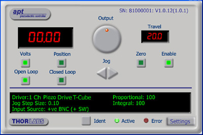
APTのGUIスクリーン
当社従来のAPTシステムソフトウェアプラットフォームは、C#、Visual Basic、LabVIEWまたはその他のActive-Xに対応する言語を使用してカスタムプログラムを作成するサードパーティの開発者向けに、ActiveXをベースとしたコントロールが付属しています。また、ハードウェア無しでカスタムプログラムの開発を行うためのシミュレーターモードも付いています。
これらの共通のソフトウェアプラットフォームにより、あらゆるKinesisとAPTコントローラをシングルアプリケーションに簡単に組み込むことができます。ソフトウェアツールは1セット習得するだけで共通した操作が可能です。シングルチャンネルシステムからマルチチャンネルシステムまで、あらゆるコントローラを組み合わせ、全てを1台のPCのソフトウェアインターフェイスから制御することが実現可能です。
このソフトウェアパッケージを使用するには2つの手段があります。GUI(グラフィカルユーザーインターフェイス)ユーティリティを使用したコントローラとの直接対話ならびに「out of the box」コントロール、またはご選択の開発言語でカスタム統合の位置決めやアライメントソリューションを簡単にプログラムできる一連のプログラミングインターフェイスです。
APTシステムソフトウェアをよりご理解いただけるために様々なチュートリアルビデオもご用意しております。ビデオではソフトウェアの概要とAPT Configユーティリティをご説明しています。また、ソフトウェアのシミュレーターモードを利用すると、コントローラを接続しないでソフトウェアを試すことができます。その方法を説明したビデオもあります。これらのビデオは「APTチュートリアル」タブ内のリンクからご覧いただけます。
ソフトウェア
Kinesis バージョン 1.14.47
このKinesisソフトウェアパッケージには、当社のKinesisならびにAPT™システムコントローラを制御するためのGUIが含まれています。
下記もご用意しております:
- 通信プロトコル
ソフトウェア
APT バージョン 3.21.6
このAPTソフトウェアパッケージには、当社のAPT™およびKinesisシステムコントローラを制御するためのGUIが含まれています。
下記もご用意しております:
- 通信プロトコル
Kinesis®ソフトウェアでは新しい.NETコントロールが使用でき、最新の最新のC#, Visual Basic, LabVIEW™、ほかの.NET対応言語を使用する開発者がカスタムにプログラムを作成することもできます。
C#
このプログラミング言語はマルチプログラミングパラダイムやマルチプログラミング言語が使用可能となるよう設計されているため、複雑な問題が簡単かつ効率的に解決できます。型付け、命令型、宣言型、関数型、ジェネリック、オブジェクト指向、そしてコンポーネント指向が含まれます。 この共通のソフトウェアプラットフォームにより、1セットのソフトウェアツールを習得するだけで、あらゆるKinesisコントローラを簡単に組み合わせることができます。このようにして1軸システムのコントローラから多軸システムのコントローラまで、様々なコントローラを組み合わせ、全てを1台のPCのソフトウェアインターフェイスから制御することが可能となりました。
Kinesisシステムソフトウェアを使用するには2つの手段があります。コントローラを直接つないで制御を行なう付属のGUI(グラフィカルユーザーインターフェイス)ユーティリティ、またはご希望の開発言語でカスタム仕様の位置決めやアライメントを簡単にプログラムできる一連のプログラミングインターフェイスです。
Kinesisモーションコントロールライブラリの構築の参考となる実行可能なプロジェクト機能拡張例については下のリンクをクリックしてください。なお、Quick Startのプロジェクト例の実行には別の統合開発環境(IDE)(Microsoft Visual Studioなど)が必要です。C#のプロジェクト例はKinesisソフトウェアパッケージに付属する.NETコントロールで実行可能です(詳細は「Kinesisソフトウェア」タブをご覧ください)。
 | Click Here for the Kinesis with C# Quick Start Guide Click Here for C# Example Projects Click Here for Quick Start Device Control Examples | |
LabVIEW
LabVIEWは、.Netコントロールを介してKinesisまたはAPTベースのコントローラとの通信に使用できます。LabVIEWでは、ツールとオブジェクトでフロントパネルとして知られるユーザーインターフェイスを構築した後、グラフィカル表記の関数を使ってコードを追加し、フロントパネルのオブジェクトを制御します。下記のLabVIEWチュートリアルでは.Netコントロールを使用してLabVIEW内KinesisまたはAPT駆動デバイス用の制御GUIを作成するための情報をご提供しています。 LabVIEWでコントローラを制御する基本的な方法や、LabVIEW GUIを用いてデバイスを操作する前に行うべき設定の手順についても解説しています。
 | Click Here to View the LabVIEW Guide Click Here to View the Kinesis with LabVIEW Overview Page | |
こちらのページでご覧いただくAPTビデオチュートリアルは、付属のATPユーティリティに関する説明と、いくつかのプログラミング環境におけるAPTシステムのプログラミングに関する説明の2つの部分から構成されています。
免責事項:これらの動画は、当初はAdobe Flashによって作成されました。2020年のAdobe Flashのサポート終了後、これらのチュートリアルは再録画されています。各動画の下にはFlash Playerの操作ボタンが見えますが、機能はしません。
APTコントローラには、APTUserユーティリティとAPTConfigユーティリティが付いています。APTUserを用いると、直感的操作が可能なグラフィック制御パネルを介して、APTで制御するハードウェアに素早く簡単に接続することができます。APTConfigは「オフライン」ユーティリティで、メカニカルステージのタイプを事前に選択し、それらを特定のモーションコントローラに対応付けるなど、システム全体のさまざまな設定を行うことができます。
APT Userユーティリティ
下の左側の動画では、APTUserユーティリティの操作概要について説明しています。シングルチャンネルコントローラのOptoDriverは、制御用のPCが無くても前面パネルのコントローラを介して操作できます。前面パネルのコントローラに保存されている操作に関する設定は、APTUserユーティリティを使用して変更することができます。そのプロセスは下の右側の動画でご覧いただけます。
APT Configユーティリティ
シミュレートされたハードウェア構成のセットアップや、メカニカルステージの特定のモータードライブチャンネルへの対応付けなど、APT Configユーティリティを使用してAPTシステム全体の様々な設定ができます。下の最初の動画ではAPT Configの概要をご覧いただけます。シミュレートされたハードウェア構成の作成方法やステージと対応付ける方法についての詳細は、その右側の2つの動画でご覧いただけます。
APTのプログラミング
APTソフトウェアシステムは、ActiveXコントロールのコレクションとして実装されています。ActiveXコントロールは言語に依存しないソフトウェアモジュールで、グラフィカルユーザーインターフェイスとプログラミングインターフェイスの両方を提供します。ハードウェアユニットのタイプごとにActiveXコントロールのタイプがあります。例えば、Motor ActiveXコントロールはすべてのタイプのAPTモーターコントローラ(DCまたはステッパ)の操作に対応します。ActiveXコントロールは多くのWindowsソフトウェア開発環境やソフトウェア言語で直接サポートされており、そのようなコントロールがカスタムアプリケーションに組み込まれると、そこに含まれるすべての機能が即座にアプリケーションで利用できるようになります。下の動画では、LabVIEW、Visual Basic、Visual C++によるAPT ActiveXコントロールの基本的な使用方法について説明しています。これ以外に、LabWindows CVI、C++ Builder、VB.NET、C#.NET、Office VBA、Matlab、HPVEEなどの多数の言語でもActiveXはサポートされています。これらの言語環境についてはチュートリアルのビデオでは特に取り上げていませんが、動画内の考え方の多くは他の言語環境でも適切に使用できます。
Visual Basic
Part 1ではVisual Basicで動作するAPT ActiveXコントロールを設定する方法について説明しており、Part 2では独自の位置決めシーケンスをプログラミングする方法について説明しています。
LabVIEW
LabVIEWはActiveXをフルサポートしています。下の一連のチュートリアルビデオでは、APTによる独自のモーションコントロールシーケンスを作製する際の基本的な構成要素を示しています。まずソフトウェア開発中にオンラインヘルプを呼び出す方法をご紹介します。Part 2ではAPT ActiveXコントロールの作成方法をご紹介します。ActiveXコントロールではメソッド(機能)とプロパティ(数値設定)の両方を設定できます。Part 3と4では、ActiveXコントロールで示されたメソッドとプロパティを作成してワイヤで接続する方法をご紹介します。最後に、Part 5では全体をまとめて、独自の移動シーケンスを実行するLabVIEWのプログラム例をご紹介します。
Part 1:オンラインヘルプへのアクセス方法
Part 2:ActiveXコントロールの作成方法
Part 3:ActiveXのメソッドの作成方法
Part 4:ActiveXのプロパティの作成方法
Part 5:ActiveXコントロールの開始方法
下のチュートリアルビデオでは、メソッドおよびプロパティのノードを作成する別の方法について説明しています。
ActiveXメソッドの作成方法(別の方法)
ActiveXプロパティの作成方法(別の方法)
Visual C++
Part 1ではVisualC++で動作するAPT ActiveXコントロールを設定する方法について説明しており、Part 2では独自の位置決めシーケンスをプログラミングする方法について説明しています。
MATLAB
当社のAPTポジショナにMATLABおよびActiveXコントロールを使用する場合は、こちらの資料をご覧ください。
プログラマー向けとして、LabVIEWでAPTソフトウェアをプログラミングする方法もこちらからご覧いただけます。
| Posted Comments: | |
user
(posted 2024-03-14 20:04:00.35) Hello I've started to use your position aligning devices due to unwanted beam drift by thermal lensing within an AOM(Acousto optic Modulator).
I've connected the Xdiff, Ydiff to the piezo controller( Thorlabs MDT693B). But since the piezo controller only allows external control of positive voltage, the bipolar feature of the position aligner makes it hard to apply to it. Is there any way to apply the position aligner to normal piezo controllers.
Also, when I checked the voltage output. The Xdiff output polarity was the opposite with the software displayed volatge. For example, for Xdiff, when I output 5V on the software, the real output was -5V. However Ydiff output was working well.
Is there something wrong with the product I have?
Best regards. spolineni
(posted 2024-04-02 09:19:52.0) Thank you for reaching out. I will contact you directly to provide further assistance in resolving this matter. Tyler Heritage
(posted 2024-01-09 12:37:20.56) Currently working through a similar situation as stated by others. Trying to write to a csv or other through Labview in order to record position values over time. Could you send me the example file? cstroud
(posted 2024-01-12 11:08:32.0) Thank you for reaching out. I will contact you directly to send over some Labview examples. user
(posted 2023-06-20 07:31:31.933) Hello, I'm using a KPA101 with a PDQ80A sensor and I want to read and extract the X Diff, Y Diff and SUM data using Labview. Can you please send me an example? Thanks, fguzman
(posted 2023-06-23 09:23:11.0) Thanks for your enquiry. We have a Labview guide in our Kinesis Tutorials https://www.thorlabs.com/newgrouppage9.cfm?objectgroup_id=3180&tabname=Kinesis%20tutorials. I will contact you directly for an example in how to plot XY position of KPA101. Natalia Orlova
(posted 2023-04-20 13:48:15.52) Hi there, my name is Natalia Orlova and I'm in charge of the high-throughput two-photon imaging core (two dual beam MesoScopes, a few single beam conventional two-photon microscopes, light sheet microscopes) at the Allen Institute. Currently I'm working on a monitoring software for our systems, and one of the components is the Kinesis cube + PSD detectors. My entire app is in Python: it would be great to have a python adapter for the Kinesis SDK/API. Thank you!
Natalia Orlova JReeder
(posted 2023-04-24 04:19:05.0) Thank you for your enquiry. You should not need a Python Adapter in order to use the KPA and Kinesis SDK/APIs in Python. I have reached out to you to provide examples and further information on how to control the KPA in Python. Bob Cacho
(posted 2023-03-22 22:50:54.32) Purchased a KPA101 auto aligner, PDP90A sensor, and TPS002 power supply - I notice that the sensor wasn't detecting the laser in the -X/-Y or +X/-Y positions in the Kinesis program. I thought the sensor was bad, had it replaced same problem. I notice when the sensor was plug-in to the KPA101 the -15volt power supply when down to -0.1V. The PDP90A requires +/-5volts, does the +/-15volts get converted down to +/-5Volts. My question is what's the problem? do'neill
(posted 2023-04-05 11:50:24.0) Response from Daniel at Thorlabs. I am sorry to hear this I will reach out to you directly to discuss this with you. Bob Cacho
(posted 2023-02-15 20:25:32.063) Hi, I'm using a KPA101 with a PDP90A sensor and I want to
read the X Diff and Y Diff data using Labview. Can you please send me an example, I'm new in Labview?
Thanks, Bob DJayasuriya
(posted 2023-02-16 11:09:18.0) Thank you for your inquiry. We have got in touch with you directly, to help with your application. Matin Jafari
(posted 2022-11-15 09:06:42.733) Hello,
We are using KPA101, and I can see XDIFF, YDIFF, and SUM on the screen. For an application, we have to save these values over long periods of time, for example, five days. How can I do that? I have searched the Kinesis software but i could not find any function or button which does this for me.
Best Regards; cwright
(posted 2022-11-17 05:22:49.0) Response from Charles at Thorlabs: Thank you for your query. The Kinesis GUI software does not have this ability. You can however use the DLLs to request the specific values from the device and then log them to a CSV file. This would require writing a program to do so. We have guides for programming our devices in C# and LabVIEW, which can be found here: https://www.thorlabs.com/newgrouppage9.cfm?objectgroup_id=10285
There is also an example C# program for the KPA101 on our Github, which is found here: https://github.com/Thorlabs/Motion_Control_Examples/blob/main/C%23/KCube/KPA101/Program.cs
The DLLs are found in the installation folder which by default is here: C:\Program Files\Thorlabs\Kinesis. The DotNet_API help file is also in that location and explains the functions you would need. In particular you should look at QuadStatus() to get the PositionDifference and Sum properties. Yi Chu
(posted 2022-11-08 14:48:00.633) Dear Sir/Madam,
We are using KPA101 with PDQ80A, connected to a Linux PC with USB. I wrote a python script using the APT protocol to talk to the KPA101 to get readings of the PDQ80A for a fast steering mirror. Every time the PC sends a request status update message, it takes about 15 ms for the KPA101 to send back a get status update message. This gives around 60 readings per sec which is very slow for a fast steering mirror. Is there any way to improve this delay? Or is there an alternative way to get the readings from KPA frequently over USB without repeatedly sending request status update messages? DJayasuriya
(posted 2022-11-09 09:23:16.0) Thank you for your inquiry. We have got in touch with directly to troubleshoot your issue. ZHU SHAODI
(posted 2022-03-29 14:46:26.517) I can not read the postion data from the screen on KPA101 when using PDP90A, but it is availble through APT software. Seems my controller can only display the raw xdiff and ydiff voltage. Is it an freature or something wrong with my controller? DJayasuriya
(posted 2022-03-30 09:35:34.0) Thank you for your inquiry. On the KAP101 displays the Signals received
from detector, e.g. XDiff and YDiff, Signals output to rear panel SMA connectors and the operation mode i.e open or closed loop. (please see https://www.thorlabs.com/drawings/148cdb3066adcb11-8D9E52F7-EF82-FC97-85BCC31EE31C2412/KPA101-KPA101ManualforAPT.pdf, page 24). Lorenz Keck
(posted 2022-01-13 16:05:35.25) Dear madam or sir,
I am working at the National Institute of Standards and Technology. My group just purchased a KPA101 K-Cube and we use it in combination with a PDP90A and a laser to monitor the position of a stage.
We need to use the labview integration with Kinesis. For this, we set up the communication using the .NET classes in labview and can open and close the communication with our KPA101. However, we cannot figure out, how to extract the position readouts into a labview variable. The required class for this seems to be not accessible.
Is it possible to get technical support on this for our group highly important topic?
It would be great if a technician would reach out to me via email. Thank you a lot for considering to help!
Kind regards,
Lorenz Keck 上月 準平
(posted 2022-01-11 10:45:35.92) APTソフト内の移動距離を手入力で変更できると思いますが、これをエクセルに記録している数値をAPTソフト内の移動距離に入力し、動作させていのですが、可能でしょうか。 Sicheng Lu
(posted 2021-06-07 11:22:50.043) I connect KPA101 to the PC, and the position data can be displayed on Kinesis. How can I save the position data in Excel format? jcater
(posted 2021-06-07 04:30:15.0) Response from Jack at Thorlabs: Thank you for your feedback. Unfortunately at this moment in time it is not possible to extract the KPA101's positional data and save to a .csv file. This will have to be done in a third party application using the .NET APT and by using the KPA101's XYPosition struct to write the X and Y position to a file. I will reach out to you with a LabVIEW example of how to do this. Sicheng Lu
(posted 2021-06-07 11:14:48.19) I connect KPA101 to the PC, and the location data can be displayed on Kinesis. How can I save the location data on the PC in Excel format? YLohia
(posted 2021-08-27 02:32:22.0) Thank you for your feedback. Unfortunately, at this moment in time, it is not possible to extract the KPA101's positional data and save to a .csv file. This will have to be done in a third party application using the .NET APT and by using the KPA101's XYPosition struct to write the X and Y position to a file. We have reached out to you with a LabVIEW example of how to do this. Wade Bortz
(posted 2021-05-12 14:38:09.41) We've got a pair of KPA101's monitoring our sun sensors here on the DKIST solar telescope in Maui. I'm having a problem where I have to climb up on the optical support structure to reset the Control Mode to Monitor each time the power is cycled. Is there any way to store that monitoring setting across power cycles? Thanks! DJayasuriya
(posted 2021-05-24 04:42:09.0) Thank you for your inquiry. yes this is correct, each time the device is power cycled the setting get reset. This is due to a safety feature in the device. We will get in touch with you directly to discuss your application and find a solution. Hong Fang zhang
(posted 2020-11-17 11:24:22.41) when I use KPA101 with senor PDP90A,I cant find the correct configuration to read X Diff and Y Diff in labview. Can u give me a example about this in labview ?
thanks a lot. cwright
(posted 2020-11-17 12:02:39.0) Response from Charles at Thorlabs: Hello and thank you for your query. This would use the PositionDifference property from the PositionAlignerStatus class. I will email you with an example. Francesco Vedovato
(posted 2019-12-17 09:10:05.68) I am Francesco Vedovato from the University of Padua. We used your KPA101 to realize a closed-loop feedback system to drive a piezo-driven mirror (by another company) in an optical system exploiting light at 1064 nm. We used your KPA101 in conjunction with a PSD and an amplifier (by other companies) and it worked well in the first prototype we implemented.
However, I would have more information about the functionality of the KPA101 in "closed-loop mode". In the manual it is stated that, "when the KPA101 unit is switched to closed loop mode, the spot moves towards the center of the display".
It is possible to set (via hardware or software) a different target position on the display with respect to its center? Do you have any other suggestion?
If the question is not clear, please contact me.
Cordially,
Francesco Vedovato
===================================
Francesco Vedovato, PhD
Research Fellow in the QuantumFuture Group
Department of Information Engineering
Via Gradenigo 6/B, 35131 Padova, Italy
University of Padua
Mail: francesco.vedovato@dei.unipd.it
Phone: +39 049 9817490
Mobile Phone: +39 3405470664
Google Scholar link
=================================== cwright
(posted 2019-12-19 06:07:20.0) Response from Charles at Thorlabs: Hello Francesco. Unfortunately you cannot set an offset in the software in order to centre at a specific position in closed-loop mode but I will reach out to you directly to see if we can help find a satisfactory solution for you. steve
(posted 2019-03-05 15:58:11.95) To operate in Monitor Mode, after power cycling the Kinesis KPA101 Position Aligner, its "Mode" must be changed from its power-on default of "Open loop" to "Monitor".
This is done by pressing its MENU button, then rotating its knurled wheel downward
so that its display reads :
"1 Control mode"
Then press its MENU button again so its display now reads :
"Open loop
to select"
Then rotate its knurled wheel either direction until its display reads :
"Monitor"
Then press the MENU button to save "Monitor" as the Mode.
DO NOT let the device auto-timeout and return to its normal display. If that is done, it will show Monitor as its Mode if you go into that menu again but it actually is a bug as of 1/9/2019 and is not in Monitor mode.
If not in Monitor mode, no signal position change will be measured when the control voltage is changed.
As of 1/9/2019, the KPA101 does not remember its Mode setting after power cycling.
Both of these concerns have be made known to Thorlabs rmiron
(posted 2019-03-07 01:01:21.0) Response from Radu at Thorlabs: Hello Steve. As described in the manual, on page 22, the mode indicator is not the first option that appears when one goes to select the operating mode. The sign in the top-right corner of the screen indicates the current operating mode. Regarding your suggestion about the cube starting in the operating mode that was last used, we agree that this would improve user experience, but there are some safety considerations preventing us from implementing the feature. steve
(posted 2018-11-19 13:43:51.02) Is it possible over USB to have an array of positions returned that had been acquired at high rate? This would be an alternative to and a method of obtaining time resolved positions faster than a one-by-one position request over USB. There would need to be a way to specify the acquisition rate and duration, then the acquisition would occur, then USB would send those results. rmiron
(posted 2018-11-20 06:32:14.0) Response from Radu at Thorlabs. Hello, Steve. This depends on the required acquisition rate. The fastest way to keep track of the positional data would be to read the analog signals output by the XDiff and YDiff ports in closed-loop mode. The polling rate will only be limited by the sampling rate of the DAQ card you would employ, or by the 100 kHz bandwidth of the signals. In order to collect the same data over USB, you would need to write a piece of code which uses or .NET API, our C API or our serial communications protocol. I expect the maximum polling rate that you can achieve via USB is on the order of a few hundred Hertz. Writing your own program for controlling KPA101 would of course enable you to control the acquisition duration and rate (as long as it is below that max. achievable figure). I will contact you directly in case further assistance is required. 1611820688
(posted 2018-09-27 06:21:05.997) Hi, I have a PDP30C with the KPA101.I try to interface with this across USB to get the position data (Xdiff,Ydiff,Sum).I've downloaded the Kinesis,and I could see the positon data from the panel in labview.But how can I get the position data out of the panel?Because I just want the position data (Xdiff,Ydiff,Sum),and write control algorithm on my own rather than just click the panel button.
So how I get the position data by labview not in the way of panel? rmiron
(posted 2018-10-01 12:30:33.0) Response from Radu at Thorlabs: You will need to read the Sum and the PositionDifference attributes of the PositionAlignerStatus class, from the KCube.PositionAligner.CLI. I will contact you directly in case further assistance is required. michael.nickerson
(posted 2017-10-18 11:09:29.037) Unfortunately this cannot interface with the TIM101, and thus is unable to control any of the PIA line of piezo controllers. It would be very useful if this KPA101 could somehow control the PIA line of piezo-inertial actuators. AManickavasagam
(posted 2017-10-27 11:42:34.0) Response from Arunthathi at Thorlabs: Thank you for your query. Unfortunately, without external elctronics there is no way to control TIM101 with KPA101 for beam stabilisation/tracking.
We will note this requirement and notify our engineers. tricejp
(posted 2016-06-09 15:54:21.787) Hi,
I have a PDP90a with the TQD001. We are interfacing with this across USB to get the position data (X,Y,Sum,Xpos Ypos...). What is the ~ max sample rate across the USB that we can expect to get from the TQD001? Thanks bwood
(posted 2016-06-13 05:04:47.0) Response from Ben at Thorlabs: Thank you for your feedback. The fundamental limiting factor is the speed of the data exchange between the PC and the TQD001. When the read command is issued, it has to go through whichever software you are using, the USB drivers, and than a USB to serial conversion at the cube. Then the embedded processor has to interpret the command, put together a response and the response has to go through the same channels in reverse order. Although this happens quite quickly, the response is not instantaneous and will be application specific. We would expect a frequency of around 60 readouts per second. pauline.belzanne
(posted 2016-04-22 12:16:02.957) Hi,
I have a PDP90A with a TQD001. I have checked that the voltage delivered by the software for XDIFF and YDIFF was the same on an oscilloscope or a multimeter. I have a good result for YDIFF but for XDIFF I have a very big difference. I've already tried to removed the cable or change the chanel, but I have the same issue.
Do you have an idea to solve this problem?
Thanks. besembeson
(posted 2016-04-22 09:31:25.0) Response from Bweh at Thorlabs USA: I have contacted you to discuss your application and observations further. ysu
(posted 2016-04-18 22:13:52.407) Hi! I have signal displayed on the software, but no voltage output from the SAM. I use it in the monitor mode. It worked fine before, but I don't know why this problem happens now. How can I fix it? bwood
(posted 2016-04-18 10:34:27.0) Response from Ben at Thorlabs: I am sorry to hear about your difficulties here. I will contact you directly for further details, to help us troubleshoot this issue. user
(posted 2013-11-06 11:08:35.927) Hi! Is the signal of the x_Diff and y_Diff output a ground referenced signal or a floating source?
Thanks jlow
(posted 2013-11-14 04:53:22.0) Response from Jeremy at Thorlabs: The signals are referenced to ground. jlow
(posted 2012-11-05 12:01:00.0) Response from Jeremy at Thorlabs: When operating in 'Monitor' mode, the X axis (XDIFF) and Y axis (YDIFF) difference signals from the detector, are
fed through to the rear panel SMA connectors. Using the typical definition of quadrants in circles, the XDIFF is "(Q2 + Q3) - (Q1 + Q4)" and the YDIFF is "(Q1 + Q2) - (Q3 + Q4)". For more detail information on that including schematic diagrams, please refer to Section 4.2 and 4.4 of the manual (http://www.thorlabs.com/Thorcat/17800/TQD001-Manual.pdf). hrudka
(posted 2012-11-05 13:14:45.21) Dear Thorlabs. I have not found information about getting a beam's position of X_DIFF and Y_DIFF and SUM voltages in monitor mode. I am using a 4quadrant diode PDQ80A.
Please help me on this.
Kind regards!
Marek Hudec tcohen
(posted 2012-05-08 09:12:00.0) Response from Tim at Thorlabs: Unfortunately, we currently do not have a document analogous to the APT Motor Controllers Host-Controller Communications Protocol for the TQD001. We are working to provide a protocol document and I will contact you to update you with this information. dpristinski
(posted 2012-05-03 14:48:50.0) Is there a USB communication protocol description for the TQD001 aligner available? Something similar to the motor controllers communication protocol which is on CD. Lou; leichner
(posted 2009-05-21 14:57:37.0) Unfortunately I think we will need additional information regarding your applicaiton. But we can sy that position values state the following:
The system reads the signals Xdiff and Ydiff from the sensor (which are proportional to the light beam position) and outputs Xpos and Ypos (which should really be called Xout and Yout).
Operating modes:
In “monitor” mode: Xpos = Xdiff and Ypos = Ydiff.
In “open loop” mode: Xpos = 0 and Ypos = 0 constant.
In “closed loop” mode: Xpos, Ypos is the output of the PID controller that is trying to maintain zero Xdiff and Ydiff values.
X,Y display modes:
In “difference” mode, the display shows Xdiff and Ydiff, (regardless of the operating mode).
In “position” mode, the display shows Xpos and Ypos, (regardless of the operating mode). m.j.rossewij
(posted 2009-05-20 05:41:09.0) TQD001 manual figure 4.8 suggests that a XPOS setpoint can be subtracted from the normalized XDIFF signal (e.g. to correct for errors due to asymetric beams). However, the APT GUI and software interface do not seem do have this function. Only for open loop is the SetPositionOutputs available to force Xpos to fXPos. (Or has fXPos an undocumented double function, where it is in closed loop subtracted from Xdiff)? srubin
(posted 2008-12-16 12:54:45.0) The PDP90A is listed in the price boxes at the bottom of the page but it is not compatible with the T-Cube sold on this page. technicalmarketing
(posted 2008-06-11 13:35:39.0) Reply from Inge at Thorlabs: We made the following measurements for you. The closed loop bandwidth is up to 200 Hz using 10% of the full positioning range available. Open loop bandwidth (X Difference, Y Difference and Sum signals) is up to 100 kHz (-3dB). lsandstrom
(posted 2008-05-16 01:47:14.0) What is the closed loop / open loop performance on the PDQ80A and TQD001 combination? |
用コントローラ")
 ズーム
ズーム
- ユニット上での制御や位置読み出しのためのコントロールパネルと有機EL(OLED)ディスプレイ
- 2つの双方向トリガーポート(外部機器からの信号読み取りや外部機器の制御用)
- 付属のUSBケーブルでPCに接続
- Kinesis®ならびにAPT™ソフトウェアパッケージに対応
- コンパクトな設置面積:60.0 mm x 60.0 mm x 49.2 mm
- 電源は付属しません(下記参照)
- パルスレーザに対してのご使用はお勧めしません。
K-Cube™ビーム位置調整用アライナKPA101は、当社の4分割位置センサならびにラテラル効果位置センサーヘッド製品に使用する設計です。上面の有機EL(OLED)ディスプレイ付き制御パネルでユニット制御と位置読み出しができます。 OLEDディスプレイにはバックライトが付いており、上面のメニュー選択により明るさの調整や消灯が可能です。 ユニット前面には双方向のトリガーポートが2つあり、5 Vの外部ロジック信号を読み取ることや、5 Vロジック信号を出力して外部機器を制御することができます。ロジックレベルの調整や、トリガ信号の入力あるいは出力の設定は、それぞれのポートごとに独立に行うことが可能です。
このユニットは当社の新しいKinesisソフトウェアパッケージならびに従来のAPTコントロールソフトウェアに対応します。詳細は「モーションコントロールソフトウェア」のタブをご覧ください。 こちらのモジュールには電源が付属しませんのでご注意ください。対応可能な電源は下記をご参照ください。
動作
K-Cube KPA101はユニット上で手動操作するほかに、USBで接続したPC上で当社の新しいKinesisソフトウェアパッケージまたは従来のAPT(Advanced Positioning Technology)ソフトウェアパッケージを利用して操作することができます。このオートアライナは、どちらから操作しても開ループならびに閉ループのどちらのモードでも動作可能です。これらの2つのモードでは、X軸方向の差信号(左の和信号-右の和信号、X DIFF)やY軸方向の差信号(上の和信号-下の和信号、Y DIFF)、そして総和信号(SUM)を生成し、ターゲット画面に表示します。
開ループモードでは、ターゲット画面に表示される差信号のX DIFFとY DIFFは、ユニット背面のSMAコネクタの出力信号とは一致しません。X DIFFとY DIFFのSMA出力信号は位置要求信号であるX OUTならびにY OUTを表しますが、ゼロもしくは閉ループ動作時の最後の値に固定されています。開ループモードではディテクタの手動アライメントが可能です。おおよそのアライメントができたらユニットを閉ループモードに設定し、システムの自動アライメントを開始させることができます。
閉ループモードでは、KPA101内部のDSPプロセッサによりX DIFFならびにY DIFFの位置要求信号が出力され、2つの独立したフィードバックループが動作します。ユニット背面のSMAコネクタから出力されたそれらの信号は、ビームの方向を操作するための素子への入力信号として用いられ、ビームはディテクタの中央にくるように制御されます。比例、積分、微分(PID)の各定数は調整可能で、ターゲット位置の変化に対するフィードバックループの応答性を微調整することができます。 浮動小数点演算を行うので、制御ループのPID定数の選択の幅が広く、それにより高精度と低ノイズが実現されています(詳細はマニュアル内の「Appendix B」をご覧ください)。また、オートアライナを用いて安定化できるアクチュエータの種類も広がります。さらに、ユニットにはノッチフィルタが内蔵されており、このユニットを組み込んだシステム特有の自然共鳴の影響を防ぐことができます。これによりジンバル式ピエゾミラーマウントのように機械的共振の影響を受けやすいアクチュエータでも安定化することができます。
ユニットをUSBインターフェイス経由で制御すると、ユニットの開ループ出力もデジタル値でPCに送られます。なお、安定した閉ループ動作が可能なのは連続発振(CW)レーザのみです。K-Cube KPA101をパルスレーザに対して使用することはお勧めしません。

 ズーム
ズーム- ±15 V/5 V電源
- TPS002: 最大2台までのMini-DIN入力端子付きK-Cube™またはT-Cube™用*
- USBコントローラーハブによって電源供給と通信が可能
- KCH301: 3台までのK-CubeまたはT-Cube用
- KCH601: 6台までのK-CubeまたはT-Cube用
TPS002では最大2台までのK-Cube*やT-Cubeに電源を供給できます。K-CubeやT-CubeをPCへ接続するには、個別のUSBケーブルが必要です。
USBコントローラKCH301は3台、KCH601は6台までのK-CubeやT-Cubeをサポートするハブ部分と、壁コンセントに差し込むだけでハブとハブに接続された全てのCubeに電力を供給する電源部分から構成されています。ハブが供給できる最大電流は10 Aですので、お使いになるCubeの合計電流が10 A以上にならないことをご確認ください。こちらのハブをご使用いただくことで、1つのUSB接続によって、複数のK-CubeやT-CubeとのUSB接続が実現します。
接続用USBコントローラーハブについての詳細は、こちらからご覧いただけます。
*電源ユニットTPS002は1台のコントローラ(KNA-VISまたはKNA-IR)、または1台のドライバKLD101にしか電力を供給できません。ユニットを追加すると電流リミット値を超える可能性があるので、そのようなご使用は避けてください。