レーザー用ビュワーカード(センサーカード)

- Detect Wavelengths from UV to MIR
- Handheld Photosensitive and Liquid Crystal Cards
VRC1
VRC2
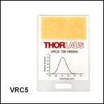
VRC5
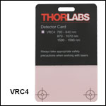
VRC4
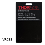
VRC6S
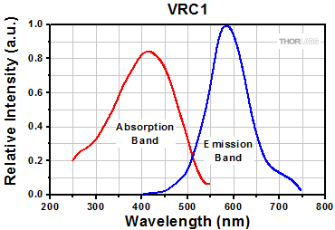
250 to 540 nm
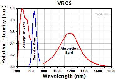
400 to 640 nm
and 800 to 1700 nm
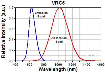
700 to 1400 nm
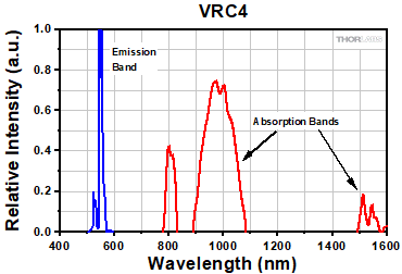
790 to 840 nm,
870 to 1070 nm,
and 1500 to 1590 nm
1.5 to >13.2 µm

Please Wait
特長
- UV域、可視(VIS)域、近赤外(NIR)域、中赤外(MIR)域用ビュワーカード
- 1 nW/cm2の低放射光まで検出
- 吸収波長範囲または感度曲線がカードにプリント
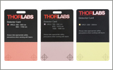
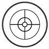
ビュワーカード(センサーカード)内の検出エリアでは、UV光、可視(VIS)光、近赤外(NIR)光または中赤外(MIR)光が当たった位置が可視化されます。各カード(VRC5を除く)は、アライメント工程で使用しやすいようカードの端にまで検出領域が及びます。また、レーザ光のコリメートに使用できる同心円と十字のパターンが2個刻印されています。
これらのセンサーカードはレーザービームブロック用ではありませんのでご注意ください。また、レーザービームを取り扱う場合は適切な安全対策を行ってください。詳しくは、「レーザの安全性」タブをご覧ください。
レーザービームをアライメントする方法
レーザを光学系に取り付ける場合、まず行うべきは、所望の光路設定をするためビームの水平度と方向を調整することです。このようにして設定されると、ビームをうまく迂回させてシステム内の光学素子を透過するように誘導できるだけでなく、システムのアライメントを調整することによって得られる結果が予測しやすくなり、再現性が高くなります。下記のセクションではそれぞれの方法について説明しています。
実験および機器についての「Insights-ヒント集」はこちらからご覧いただけます。
レーザービームのポインティング角度を水平にアライメントする方法
0:00 - はじめに
1:25 - レーザービームのポインティング角度を水平にし、アライメントする方法
4:09 - ビームを迂回させて任意の光路にアライメントする方法
Click to Enlarge
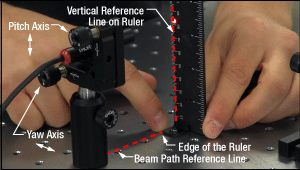
図2: ビームは、光学テーブルのタップ穴のラインに対して平行になるようアライメントすることができます。キネマティックマウントのヨー調整でビーム角度を調整し、ルーラをタップ穴のラインに沿ってスライドさせるときに、ビームの照射位置が横方向で動かないようにします。
Click to Enlarge
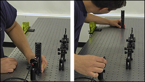
図1: :ビーム方向を光学テーブルの表面に対して水平にするには、レーザ用キネマティックマウントのピッチ調整を使用します(図2)。ビームがテーブル表面に対して平行になっている状態は、ビーム高がレーザ前面に近い位置(左)と遠い位置(右)でパワー測定値が同じであることを確認することで行います。
キネマティックマウントのピッチ(チップ)とヨー(ティルト)を調整することで、レーザ角度の微細な補正を行うことができます。この角度調整は、コリメート光を光学テーブル表面などの基準面に対して、あるいはテーブルのタップ穴のラインに沿ってなど基準面内の特定の方向に対してアライメントするときなどで行います。
マウントのアジャスタを使用する前に
まず、キネマティックマウントの各アジャスタを回して移動範囲の中央に移動させます。これにより調整範囲が足りなくなるリスクが少なくなります。また調整範囲の真ん中にアジャスタがあると、マウントのポインティング安定性が良くなります。
その後、レーザを支えるポストやポストホルダなどのオプトメカニクス部品を調整することで、レーザの高さ、位置、向きの粗調整を行います。 調整後はすべてのロックネジが締め付けられていることを確認してください。
ビームをテーブル表面に対して平行にする場合
レーザ光のレベル調整のため、アライメントツールを用いて、マウントのピッチアジャスタによる微細な調整を繰り返す必要があります。
まず光源から近い位置と遠い位置のビームの高さを測定します(図1)。2つの間の距離が長ければ長いほど、確度は高くなります。2つの位置のビーム高が一致するまで、キネマティックマウントのピッチを繰り返し調整します。
ピッチ調整により光源の高さも変わります。動画の例では、光源に近いビーム高は当初82 mmでしたが、最初のピッチ調整で83 mmに上がっています。
ビームを水平に調整した後は、レーザを支えるオプトメカニクス部品を所望の高さに調整します。または2つのステアリングミラーをレーザの後ろに置き、違う方法でアライメントすることもできます(詳細については同セクション内に記載されています)。ステアリングミラーは特に装置自体の角度調整が難しいレーザ装置のビームの高さと方向の調整に有用です。
ビームをタップ穴列に沿った向きに調整
ビームをテーブルのタップ穴列に対して平行にアライメントする場合もアライメントツールとマウントのヨーアジャスタの反復調整が必要になります。
アライメントツールにより、タップ穴列を基準線として、レーザ出力方向を調整できます。ルーラの底辺の端をタップ穴列に合わせて配置します(図2)。
テーブル上の基準線に対するビームの角度ズレは、ルーラに照射されるレーザースポット位置とルーラの垂直基準線の差を見ることで確認できます。取付けブラケットBHMA1を使用して水平置き型のルーラを取り付けることができます。
動画では、ルーラをタップ穴列に並行に移動し、レーザ照射位置をルーラーの1 mm単位の目盛の端に一致させるようにアライメントします。ルーラを基準線の遠い方の位置に移動させると、ルーラのビーム位置も水平方向に移動します。ルーラを遠い方の位置に配置した後、ビーム端が1 mm単位の目盛に一致するまでマウントのヨーを調整します。その後ルーラを光源の近くに移動させ、ビームの位置調整の結果を見ます。このプロセスは必要に応じて反復で行われています。
ビームを迂回させて任意の光路に沿ってアライメントする方法
1つ目のステアリングミラーは、新しい光路上に配置された2つ目のミラーに向けてビームを反射します。2つ目のステアリングミラーは、新しい光路に沿うようにアライメントします。2つのステアリングミラーでレーザ光をアライメントする手順は、Walking the Beam(ビームの移動)として説明することがあり、その結果はFolded Beam Path(折りたたまれたビーム路)と呼ばれることがあります。上の動画の例では、ビームを新しい光路にアライメントするために2つのアイリスが使用されています。新しい光路は光学テーブル面に対して平行で、タップ穴列に沿っています。
Click to Enlarge
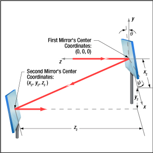
図3: 1つ目のミラーから反射されたビームは、x軸ならびにy軸まわりに、それぞれθおよびψ回転すれば、2つ目のミラーに入射します。どちらの角度も2つ目のミラーの中心位置(座標x2、y2、z2 )に影響を及ぼします。1つ目のミラーのx軸周りの回転は、マウントのピッチ(チップ)アクチュエータの移動範囲によって制限されますが、その移動範囲は、2つ目のミラーの位置と高さも制限します。
Click to Enlarge
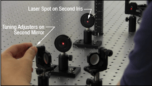
図5: 2つ目のキネマティックミラーマウントのアジャスタは、2つ目のアイリスにビームをアライメントするのに使用します。
Click to Enlarge
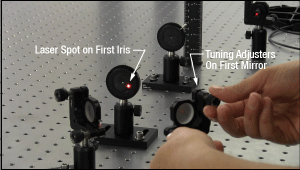
図4: 1つ目のキネマティックミラーマウントのアジャスタを調整して、1つ目のアイリスの開口部にレーザースポットを合わせています。
ミラーの高さの設定
1つ目のミラーの中心は、入射路の高さと一致させます。2つ目のミラーの中心は、新しい光路の高さに合わせてください。
アイリスのセットアップ
新しい光路はアイリスによって設定されます。動画では光路がテーブル面に対して水平となるよう、アイリスの高さが一致していることがご覧いただけます。マウント内のアイリスの高さはルーラかノギスを使用すると適度な精度で設定可能です。
アイリスが閉じているときの(小さな)開口部は、完全な中心位置にない場合があります。そのため、アイリスのビームの入力面をひっくり返すと、開口の位置がシフトする場合があります。アイリスのビーム入力面を決めたらセットアップから使用まで同じ面を使用することを推奨します。
コンポーネントの配置と粗調整
まず、両ミラーのアジャスタを回しながら移動範囲の中央に移動させます。1つ目のミラーは入射光路に配置し、2つ目のミラーは新しい光路上に配置します(図3)。1つ目のミラーのピッチ(チップ)アクチュエータの移動範囲がx周りのミラーの回転(θ )を制限するため、ミラー配置は1つ目のミラーのピッチ(チップ)アクチュエータの移動範囲によって限定されます。2つ目のミラーの位置(x2 、y2 、z2 )を選ぶときは、ピッチに加え、1つ目のミラーのヨー(ティルト)も考慮しなければなりません。2つのミラーは、1つ目のミラーの両アジャスタを移動範囲いっぱいに回さなくてすむよう配置してください。
新しい光路に2つ目のミラーを配置後、両方のアイリスを光路上に置いてください。1つ目のアイリスは2つ目のミラーの近くに、2つ目のアイリスは2つ目のミラーからできるだけ遠くに配置してください。
2つのミラーの高さはそのまま維持し、またヨーのアジャスタは触らずに1つ目のミラーを回転させて、光を2つ目のミラーに向けます。1つ目のミラーのピッチアジャスタを調整して、レーザースポットを2つ目のミラーの中心近くに移動させます。その後、2つ目のミラーを回転させて、ビームを新しい光路にある程度向けます。
最初に光路上に光を当て、その後、向きを調整します。
1つ目のミラーは、2つ目のミラー上にある新しい光路上の点に向けてビームをステアリングするために使用します。まず、1つ目のアイリスに当たるレーザースポットの位置を見ながら1つ目のミラーのアジャスタを調整します(図4)。アイリスの開口部の中心にレーザースポットが合えば最初のステップは終了です。
次に2つ目のミラーでビームをステアリングして、新しい光路とアライメントさせます。2つ目のミラーのアジャスタを調整して、レーザースポットを2つ目のアイリスの開口部に移動します(図5)。ピッチアジャスタがビームの高さを調整し、ヨーアジャスタがビームを横方向に移動します。2つ目のアイリスでレーザースポットが消えてしまう場合、2つ目のミラーのレーザースポットが新しい光路から離れています。
1つ目のミラーのアジャスタを調整しながら2つ目のミラー上のビーム位置を変え、1つ目のアイリスの開口部の中心にレーザースポットがあたるようにします。2つ目のミラーのアジャスタ調整を再開して、2つ目のアイリスの開口部にレーザースポットを向けます。これをレーザービームが両方のアイリスの中心を通るまで繰り返します(動画参照)。アジャスタのどれかが調整範囲の制限に近づいてしまったら、ミラーの1つ、あるいは両方の位置を変え、アライメント手順を繰り返してください。
ヨー軸のアジャスタが制限に近づいた場合、反射ビーム方向を記録しておき、ヨーアジャスタを調整範囲の中央に回転させます。反射ビーム方向が記録した位置になるようミラーマウントの向きを変えます。ミラーが回転できない場合、ビームが新しい光路にほぼ沿うよう1つあるいは両方のミラーの位置を変えます。ビームの向きが微細に調整できるまでこのアライメント手順を繰り返します。
ピッチ軸のアジャスタが制限に近づいた場合、2つのミラーの間の距離を長くするか、入射路と新しい光路の高さの差を小さくします。どちらの方法でもアライメント手順が繰り返された後、ピッチアジャスタが調整範囲の中心の近くに配置されます。
レーザの安全性とクラス分類
レーザを取り扱う際には、安全に関わる器具や装置を適切に取扱い、使用することが重要です。ヒトの目は損傷しやすく、レーザ光のパワーレベルが非常に低い場合でも障害を引き起こします。当社では豊富な種類の安全に関わるアクセサリをご提供しており、そのような事故や負傷のリスクの低減にお使いいただけます。可視域から近赤外域のスペクトルでのレーザ発光がヒトの網膜に損傷を与えうるリスクは極めて高くなります。これはその帯域の光が目の角膜やレンズを透過し、レンズがレーザーエネルギを、網膜上に集束してしまうことがあるためです。
安全な作業および安全に関わるアクセサリ
- クラス3または4のレーザを取り扱う場合は、必ずレーザ用保護メガネを装着してください。
- 当社では、レーザのクラスにかかわらず、安全上無視できないパワーレベルのレーザ光線を取り扱う場合は、ネジ回しなどの金属製の器具が偶然に光の方向を変えて再び目に入ってしまうこともあるので、レーザ用保護メガネを必ずご使用いただくようにお勧めしております。
- 特定の波長に対応するように設計されたレーザ保護眼鏡は、装着者を想定外のレーザ反射から保護するために、レーザ装置付近では常に装着してください。
- レーザ保護眼鏡には、保護機能が有効な波長範囲およびその帯域での最小光学濃度が刻印されています。
- レーザ保護カーテンやレーザー安全保護用布は実験室内での高エネルギーレーザの遮光にご使用いただけます。
- 遮光用マテリアルは、直接光と反射光の両方を実験装置の領域に封じ込めて外に逃しません。
- 当社の筺体システムは、その内部に光学セットアップを収納し、レーザ光を封じ込めて危険性を最小限に抑えます。
- ピグテール付き半導体レーザは、他のファイバに接続、もしくは他のファイバとの接続を外す際には、レーザ出力をOFFにしてください。パワーレベルが10 mW以上の場合には特にご注意ください。
- いかなるビーム光も、テーブルの範囲で終端させる必要があります。また、レーザ使用中には、研究室の扉は必ず閉じていなければなりません。
- レーザ光の高さは、目線の高さに設定しないでください。
- 実験は光学テーブル上で、全てのレーザービームが水平を保って直進するように設定してください。
- ビーム光路の近くで作業する人は、光を反射する不要な装飾品やアクセサリ(指輪、時計など)をはずしてください。
- レンズや他の光学装置が、入射光の一部を、前面や背面で反射する場合がありますのでご注意ください。
- あらゆる作業において、レーザは必要最小限のパワーで動作するようにご留意ください。
- アライメントは、可能な限りレーザの出力パワーを低減して作業を行ってください。
- ビームパワーを抑えるためにビームシャッタや フィルタをお使いください。
- レーザのセットアップの近くや実験室には、適切なレーザ標識やラベルを掲示してください。
- クラス3Rやクラス4のレーザ(安全確保用のインターロックが必要となるレーザーレベルの場合)で作業する場合は、警告灯をご用意ください。
- ビームトラップの代用品としてレーザービュワーカードを使用したりしないでください。
レーザ製品のクラス分け
レーザ製品は、目などの損傷を引き起こす可能性に基づいてクラス分けされています。国際電気標準会議(The International Electrotechnical Commission 「IEC」)は、電気、電子工学技術関連分野の国際規格の策定および普及を行う国際機関で、IEC60825-1は、レーザ製品の安全性を規定するIEC規格です。レーザ製品のクラス分けは下記の通りです
| Class | Description | Warning Label |
|---|---|---|
| 1 | ビーム内観察用の光学機器の使用を含む、通常の条件下での使用において、安全とみなされているクラス。このクラスのレーザ製品は、通常の使用範囲内では、人体被害を及ぼすエネルギーレベルのレーザを発光することがないので、最大許容露光量(MPE)を超えることはありません。このクラス1のレーザ製品には、筐体等を開かない限り、作業者がレーザに露光することがないような、完全に囲われた高出力レーザも含まれます。 |  |
| 1M | クラス1Mのレーザは、安全であるが、望遠鏡や顕微鏡と併用した場合は危険な製品になり得ます。この分類に入る製品からのレーザ光は、直径の大きな光や拡散光を発光し、ビーム径を小さくするために光を集束する光学素子やイメージング用の光学素子を使わない限り、通常はMPEを超えることはありません。しかし、光を再び集光した場合は被害が増大する可能性があるので、このクラスの製品であっても、別の分類となる場合があります。 |  |
| 2 | クラス2のレーザ製品は、その出力が最大1 mWの可視域での連続放射光に限定されます。瞬目反射によって露光が0.25秒までに制限されるので、安全と判断されるクラスです。このクラスの光は、可視域(400~700 nm)に限定されます。 |  |
| 2M | このクラスのレーザ製品のビーム光は、瞬目反射があるので、光学機器を通して見ない限り安全であると分類されています。このクラスは、レーザ光の半径が大きい場合や拡散光にも適用されます。 |  |
| 3R | クラス3Rのレーザ製品は、直接および鏡面反射の観察条件下で危険な可視光および不可視光を発生します。特にレンズ等の光学機器を使用しているときにビームを直接見ると、目が損傷を受ける可能性があります。ビーム内観察が行われなければ、このクラスのレーザ製品は安全とみなされます。このクラスでは、MPE値を超える場合がありますが、被害のリスクレベルが低いクラスです。可視域の連続光のレーザの出力パワーは、このレベルでは5 mWまでとされています。 |  |
| 3B | クラス3Bのレーザは、直接ビームを見た場合に危険なクラスです。拡散反射は通常は有害になることはありませんが、高出力のクラス3Bレーザを使用した場合、有害となる場合もあります。このクラスで装置を安全に操作するには、ビームを直接見る可能性のあるときにレーザ保護眼鏡を装着してください。このクラスのレーザ機器にはキースイッチと安全保護装置を設け、さらにレーザ安全表示を使用し、安全照明がONにならない限りレーザがONにならないようにすることが求められます。Class 3Bの上限に近いパワーを出力するレーザ製品は、やけどを引き起こすおそれもあります。 |  |
| 4 | このクラスのレーザは、皮膚と目の両方に損傷を与える場合があり、これは拡散反射光でも起こりうるとみなされています。このような被害は、ビームが間接的に当たった場合や非鏡面反射でも起こることがあり、艶消し面での反射でも発生することがあります。このレベルのレーザ機器は細心の注意を持って扱われる必要があります。さらに、可燃性の材質を発火させることもあるので、火災のリスクもあるレーザであるとみなされています。クラス4のレーザには、キースイッチと安全保護装置が必要です。 |  |
| 全てのクラス2以上のレーザ機器には、上記が規定する標識以外に、この三角の警告標識が表示されていなければいけません。 |  | |
| Posted Comments: | |
Hung Cheng
(posted 2024-03-29 21:38:39.367) Subject: Inquiry Regarding Composition of Layers in NIR Card Reflectance Signal Measurement
Dear Thorlabs,
I am currently conducting research on SD-OCT and have recently been utilizing your company's product for measurements. Upon analysis, it appears that the reflected signal comprises approximately four or five layers. I am reaching out to kindly request information on the composition of these layers from top to bottom within the NIR sensitive region.
Your assistance in providing an overview of the layers included in this profile would be greatly appreciated.
Thank you in advance for your attention to this matter.
Warm regards 康 孙
(posted 2024-01-29 16:48:49.97) 请问咱们的激光观察卡在不同的角度上观察这个入射的光斑的位置时会有明显的差别,请问这个现象该怎么解释?又怎么避免呢?谢谢! ksosnowski
(posted 2024-01-29 04:33:36.0) Hello, thanks for reaching out to Thorlabs. The surface of the VRC series viewers has a matte finish so should act like a diffuse absorber and be fairly independent of angle of incidence. However at higher angle of incidence with the input beam, the projection of the beam across the card is further spread out. Since a minimum power per area is required to make the spot visible to the human eye, the lower power density at higher angles may make this more difficult to view. I have reached out directly to discuss this application further. Benjamin Feldtman
(posted 2022-11-06 17:16:42.933) Hi Thor team,
We use the VCR4 cards extensively, but have often wished the active area was larger. Is it possible to order cards in a larger size without the engraved circles, or sheets of the stick-on active material? ksosnowski
(posted 2022-11-07 02:11:05.0) Hello Benjamin, thanks for reaching out to Thorlabs. We are able to provide larger sizes of these laser viewing materials, which come with an adhesive backing. Requests like this are best directed to techsales@thorlabs.com to confirm size and quantity requirements before we can provide a quote. Joonhak Park
(posted 2022-10-06 11:47:02.95) Dear Sir or Madam,
I am an optical engineer here, Healux which specializes in the medical industry in Korea.
I recently bought the VRC6H card for detecting a wavelength of 2940nm.
However, it was detected even at a wavelength of 1064nm. The energy was about 200mJ at 1ms pulse width and I used an ND filter of 1% to lower the intensity.
Here's a question. In this case, can a laser beam of 1064nm be detected by your VRC6H card? or is it actually a mixture of 2940nm of light?
I am looking forward to your response.
Best regards,
Joonhak cdolbashian
(posted 2022-10-24 09:45:10.0) Thank you for contacting Thorlabs. VRC6S and VRC6H is based on thermochromic liquid crystal which, thorough color change, visualize the temperature change on the surface of the viewing card when a laser beam lands on it. Thus it actual response to all wavelength (other than UV since UV may damage the liquid crystal). However its response is much slower and sensitivity lower than that of a phosphorous viewing card like VRC2 or VRC4. Therefore, those phosphorous viewing card over the VRC6S or VRC6H are recommended for laser viewing in the NIR range. user
(posted 2022-09-15 15:48:56.127) This is a great IR card, and works significantly better at the wavelengths I use than the other cards. However, the best one I have is one where the backing was carefully peeled off such that the card just has the front plastic and the fluorescing medium. It's nice because you can much more easily overlap counterpropagating beams. The card has also been cut down so that the edge of the fluorescing medium is at the edge of the card. I'm wondering if you might consider selling IR cards like this as it's quite difficult to remove the back paper without damaging the card. ksosnowski
(posted 2022-09-15 07:18:44.0) Thanks for reaching out to Thorlabs. We appreciate this insight and I am adding this to our forum for internal development so we can consider this type of feature in the future. I have reached out directly to further discuss this application. Shahad AL-Gburi
(posted 2022-06-04 14:52:11.957) Dear Sir or Madam,
I am a master student at HAWK Göttingen in the field of laser and plasma technology.
Currently I am working on my master thesis and for this I am supposed to evaluate the TruDiode 151 laser. The wavelength range is between 920nm-970nm and the power density is 10 w/cm2.
I want to visualize the laser spot and found your product (IR-Detector card) on the internet for this purpose, regarding IR-Detector card VRC4 I have the following questions:
1. can they withstand such high power?
2. can they display the laser dot visibly?
I would be grateful if you could give me more information about it.
I will be glad to answer any other questions you may have :)
Kind regards
Shahad Al-Gburi
M.Sc. Laser and Plasma Technology
Faculty of Engineering and Health Shahad AL-Gburi
(posted 2022-06-04 14:50:31.903) Dear Sir or Madam,
I am a master student at HAWK Göttingen in the field of laser and plasma technology.
Currently I am working on my master thesis and for this I am supposed to evaluate the TruDiode 151 laser. The wavelength range is between 920nm-970nm and the power density is 10 w/cm2.
I want to visualize the laser spot and found your product (IR-Detector card) on the internet for this purpose, regarding IR-Detector card VRC4 I have the following questions:
1. can they withstand such high power?
2. can they display the laser dot visibly?
I would be grateful if you could give me more information about it.
I will be glad to answer any other questions you may have :)
Yours sincerely
Shahad Al-Gburi
M.Sc. Laser and Plasma Technology
Faculty of Engineering and Health ksosnowski
(posted 2022-06-20 09:20:36.0) Thanks for reaching out to Thorlabs. Our Laser Viewing Cards are not intended for such high power density applications, and while the minimum visibility generally depends on the ambient light level, this power level is well above those thresholds. We have not performed CW damage testing on these, however customers have reported damage in IR around 700mW/cm^2 for similar cards with small beams. In some cases customers have also reported slightly higher, and it could vary some with beam size. I would recommend attenuating the beam to <300mW/cm^2 or less to test with, and by starting with a corner of the card you can slowly raise the power to observe the damage threshold in your exact setup. I've reached out directly to discuss your application further. Philipp K.
(posted 2021-11-17 03:24:01.873) Hi Thorlabs,
you once sold a version of the MIR viewing crd that was backed on a metal sheet. It was very useful for slightly higher powers and for faster recovery. My stock of these cards is slowly decaying - Is there a reason you dont offer them anymore? Will they be avalable again?
Best YLohia
(posted 2021-11-23 02:04:39.0) Thank you for contacting Thorlabs. For the updated VRC6 series, we optimized the liquid crystal material and removed the aluminum backing to improve the sensitivity of the card. We have reached out directly to discuss this further. user
(posted 2021-02-24 14:46:59.81) How long the VRC2 has to be charged in visible light before use? asundararaj
(posted 2021-02-24 03:33:59.0) Thank you for contacting Thorlabs. While we do not specify a time for charging, it typically takes a couple second to charge. To look at a beam without interruption, we recommend moving the card to move the position of the incident light spot around the active region to maintain the intensity of the excited emission. Thomas Hadnich
(posted 2020-01-30 09:12:51.613) Can you please inform me about the customs tariff number of those detector cards. YLohia
(posted 2020-01-31 09:39:18.0) Hello, thank you for contacting Thorlabs. The HTS code for the VRC5 detector card is 9027508060. Lucile SANCHEZ
(posted 2020-01-14 18:35:36.54) Hello,
could you make a card with a non reflective plastic like the VRC serie except the VRC5 but for the 780 nm?
It is quite dangerous to see the reflexion when you have two beams to consider and one that is red like 630nm and an IR beam and the red can actually being reflected on the card and damage your eyes...
Thanks a lot,
Best regards,
Lucile YLohia
(posted 2020-01-15 09:13:14.0) Hello Lucile, thank you for your feedback. I have posted your suggestion on our internal engineering and design forum for further consideration as a future update. user
(posted 2019-04-16 16:54:49.96) The plastic rim around the card is annoying. It would be ideal to have a similar card with the detector region of the card extending to the edges of the card. YLohia
(posted 2019-04-17 08:54:15.0) Hello, thank you for your feedback and my apologies for the issues caused by the borders of this card. We will certainly keep this in mind when designing the next iteration of this card. I have posted your feedback in our internal engineering forum for further consideration. dsteil
(posted 2018-09-17 13:56:41.477) Hi,
would it be possible to put the IR or UV-active materials onto a metal substrate? We do burn this cards quite often due to high average power of our femtosecond fiber amplifiers (pulse energy is not the problem), but mostly it seems that the plastic is in fact the first one to go not the coating.
Best
Daniel nbayconich
(posted 2018-09-21 09:57:14.0) Thank you for contacting Thorlabs. We can provide the fluorescent material alone on a self-adhesive backing which could then be placed on metallic surface if needed. I'll reach out to you directly to discuss our custom capabilities. felix.attila.farkas
(posted 2018-02-08 15:49:07.54) Hello Thorlabs,
I am interested in a laser protection system for some of our products categories.
Is there a laser exposure indicator foil that is not reversible?
If the product was exposed at a certain wavelength range then the foil will change permanently the color and remain like that.
Could you please give me a feedback for this?
Thanks you!
Attila nbayconich
(posted 2018-03-30 03:17:02.0) Thank you for contacting Thorlabs. It sounds like you are describing laser burn paper which can be used as an indicator of a high intensity laser. At the moment we do not supply products similar to burn paper and we have not tested our laser viewing detection cards in the same application. These laser viewing cards are generally used for just locating the position of an IR or UV source but are not intended to be used in the same application as burn paper. I will reach out to you directly to discuss your application kedves
(posted 2017-05-23 14:08:28.58) Dear Thorlabs, which laser viewing card can you recommend for 780 nm? VCR5's absorption band seems to cover 780 nm, but it has a smaller sensitive area and a shiny surface which are not advantageous. How about VCR2 and VCR4? Is there any experience how sensitive these are at 780 nm? Thanks nbayconich
(posted 2017-07-10 11:50:46.0) Thank you for contacting Thorlabs. We recommend using the VRC5 for 780nm. Our VRC2 & VRC4 IR cards do not cover 780nm in their absorption range. I will reach out to you directly to discuss the VRC2 & VRC4's sensitivity. user
(posted 2016-04-05 00:31:49.21) Can we have these in the form of alignment disks, such as the VRC2D1's which can be mounted on alignment targets? thanks! besembeson
(posted 2016-04-05 11:30:55.0) Response from Bweh at Thorlabs USA: Thanks for your feedback. We will look into expanding these alignment disks to include the VRC1 as you suggested. berkdiler
(posted 2016-03-23 16:31:40.833) I work with a wide range of IR wavelengths. I see online that there are materials to view IR without recharging. I do have your florescent viewers however since they bleach extremely fast the SM1 mounted ones are useless (since they are stationary). I see that the material VR4 only works for a short range of wavelengths however there seems to be a similar material http://www.zap-it.com/products/view-it-ir-laser-spot-targets on this website that works with a much broader wavelength. Another material I found online is http://www.sintecoptronics.com/irdetector.asp, which is a doubling ceramic.
Overall I would appreciate a lot a broadband NIR card (800-1700) without bleaching and the material to make one appears to exist. besembeson
(posted 2016-03-24 01:54:42.0) Response from Bweh at Thorlabs USA: Thanks very much for your very valuable feedback. We are going to review our viewing card offerings. ryanh
(posted 2016-02-22 04:21:17.59) Is the VRC6 detector card suitable for beam alignment of a 200W CO2 laser with a power density of approximately 200W/CM2 or will it damage the card? The laser will only be firing 1 pulse with an on time of around 50uS. Thanks. besembeson
(posted 2016-03-03 02:05:37.0) Response from Bweh at Thorlabs USA: That laser power is significantly much higher than what we have tested the card with. These are generally not recommended for high power applications. I will contact you regarding testing this. drakem
(posted 2016-02-17 15:40:48.323) It would be very helpful if the card's destructive threshold laser intensity were included. I burnt a hole in it the first time I used it. besembeson
(posted 2016-03-03 01:31:27.0) Response from Bweh at Thorlabs USA. Thanks for your feedback. These are generally not recommended for high power applications. We will look into adding some notes on our website for recommended high power levels. I will contact you regarding your damaged card. yehonatan.gilead
(posted 2015-05-21 13:07:12.287) Hello,
I can't seem to find the dimensions of the painted reticles. perhaps you could post the diameters of the small and large circles, as well as the length of the lines? jlow
(posted 2015-05-21 11:36:15.0) Response from Jeremy at Thorlabs: The line width is around 0.004". The inner circle is about Ø0.063" and the outer circle is about Ø0.288". The length of the cross is about 0.512" (same for both vertical and horizontal lines) maxl
(posted 2014-12-18 16:31:41.427) Can you offer IR Card Damage Threshold spec
Thanks for your help!
Looking forward to hearing from you soon! besembeson
(posted 2014-12-18 04:25:58.0) Response from Bweh at Thorlabs: We don't have damage threshold specification yet for these. I will contact you by email to determine if this can still be suitable for you. user
(posted 2014-07-22 17:21:31.48) Can I cut one of these cards into a small piece that would fit my sample holder, or would that destroy it? jlow
(posted 2014-08-01 11:09:06.0) Response from Jeremy at Thorlabs: These can be cut into smaller pieces. Eddie.wu
(posted 2014-07-14 16:38:22.857) Dear Sir:
our customer reply that this CRC6 card have something wrong, it can't recover the original state anymore.
Do you have any energy limitation to this card?
(they use 30W CW CO2 laser, setting to 17W, and the original beam size is 2.5mm, and the space between laser and alignment card is 2 meter)
please contact us as soon, thanks. jlow
(posted 2014-08-01 02:55:07.0) Response from Jeremy at Thorlabs: The detector area is only green between around 25 to 30°C and it's brown or black otherwise. So please make sure that the temperature of your lab is around the right temperature range to get back to the green color. We do not have a damage threshold information on this for the moment but we will update the website with the damage threshold once we have the test data. egregorio
(posted 2014-03-24 20:45:29.01) I have read in previous comments that the VRC4 has a minimum detectable power density for a pulsed laser of 250 kW/cm^2 peak @ 1064nm, 7ns, 10Hz. I have a pulsed laser at 1535 nm with 210 kW/cm^2 peak @ 1535 nm, 7 ns, 1 Hz, So, I am not sure if the VRC4 is sensitive enough. Do you know the sensitivity of this card for a pulsed laser at 1535 nm? jlow
(posted 2014-03-26 11:36:56.0) Response from Jeremy at Thorlabs: The absorption at 1535nm would be lower than that at 1064nm (see spectral sensitivity graph on the webpage) so the minimum detectable power would be higher. Therefore, the VRC4 would probably not work for you. The VRC2 would probably work better for you. The min. stimulation is around 2kW/cm^2 peak power @ 1064nm. Adjusting it to 1535nm would be around 10kW/cm^2 or so. kedves
(posted 2013-12-11 18:40:08.92) Dear Thorlabs,
Can your NIR Detector Card VRC4 be used with Ti:Sapphire laser beams? The absorption band seems to be appropriate, but how about the peak/average power density thresholds in the femtosecond pulse range? Are there any data or experiences? Secondly, I suppose that the surface of the photosensitive region is non-reflecting, is it correct? Thanks. tcohen
(posted 2014-01-09 04:27:57.0) Response from Tim at Thorlabs: Thanks for your inquiry. The VRC4 has the appropriate absorption bands, but currently our data is only for CW and Pulsed: CW: Min <2uW/cm^2 at 808nm in dark. Min Pulsed: 250 kW/cm^2 peak @ 1064nm, 7ns, 10Hz, low ambient light. Max Pulsed: 35 MW/cm^2 peak @ 1064nm, 7ns, single pulse. Unfortunately this may not scale well to the fs regime. There is not a laminate over this coating but there will be some diffuse reflection. I’ve contacted you to organize some testing. lunaysol77
(posted 2013-11-28 13:33:51.477) Hello, I have a pulsed QCL in the range 6.71 to 8.73 microns with a maximum power of 300 mW, pulse width maximum of 500 ns, a pulse repetition rate of 100 KHz and a spot size of 2.5 mm. The VRC6-card serves to this laser?. Do you have any other recomendation to detect this laser? Thanks!! jlow
(posted 2013-12-02 02:44:05.0) Response from Jeremy at Thorlabs: The VRC6 can be used to view the output from your QCL. Erik.Schmidt
(posted 2013-11-13 17:53:53.273) Hello, is the flourescent material on the VCR4-Card also available as a foil or as a paintable coating? Thx for reply! cdaly
(posted 2013-11-14 04:01:26.0) Response from Chris at Thorlabs: Thank you for your inquiry, but unfortunately, we are not able to offer the viewing materials in this format. hambitza
(posted 2013-05-13 11:27:33.783) My laser runs at 1080 nm. Does the flourescence of the VRC4D1 for 870 nm - 1070 nm "cut off" at 1070 nm or will it show some signal also 10 nm away at 1080 nm? jlow
(posted 2013-05-15 11:13:00.0) Response from Jeremy at Thorlabs: The absorption does cut off at 1070nm. For 1080nm, I would recommend using the VRC2D1 instead. doug.newman
(posted 2013-05-08 12:26:07.12) Product is currently in use. May order more. Question: are there any power-density threshold studies that have been done to note the maximum power/heat the cards may withstand before being damaged? Obviously this question has been asked before; just wondering if there are any updates?
Thank you.
doug jlow
(posted 2013-05-14 09:27:00.0) Response from Jeremy at Thorlabs: We do not have the damage threshold spec at the moment. We are testing the damage threshold and we will update the webpage with the damage threshold spec once we are finished with the testing. bowen
(posted 2013-02-28 11:07:27.38) Which card should I use for a 660-680nm source (your diode SLD1332V)? Thanks! cdaly
(posted 2013-03-06 09:21:00.0) Response from Chris at Thorlabs: Thank you for using our web feedback. There's no card we recommend for this particular wavelength range. 660-680 nm is red light, which should be visible without the use of one of these. These are typically designed for use with UV or IR wavelengths. A few of these do have span wavelength in the visible, but these are always in addition to other non-visible ranges. jlow
(posted 2012-10-22 16:33:00.0) Response from Jeremy at Thorlabs: The guideline value for the damage threshold for VRC2 is 60MW/cm^2 (peak power, for Nd:YAG laser @ 1064nm - single 7ns pulse). Unfortunately we do not have a damage threshold spec for CW. mlpgil
(posted 2012-10-19 15:54:48.483) We need to use the VRC2 card, with a laser beam with 1064nm, and 30W of maximum power. We need to know what is the maximum power and energy density that could whitstands the VRC2 card.
Thank you, tcohen
(posted 2012-03-29 11:12:00.0) Response from Tim at Thorlabs to Raffi: Thank you for your feedback! The VRC4 has a sharp cut on working range at 795nm whereas the VRC2 and VRC5 have some low absorption which is nonzero at 795nm. Therefore, at this wavelength it is difficult to see performance differences between the three. To clarify, we will update our website presentation to include graphs for future users to compare. If you have found that your VRC2/5 are working better for you and you have no need for the VRC4, we will fully refund your purchase. raphael.cohen3
(posted 2012-03-29 07:36:09.0) we use a 795nmn laser so we bought a VRC4, according to your graphs
but it is not as effective as VRC2 & 5 that we have
can you explain this?
Thanks
Raffi bdada
(posted 2011-10-18 14:19:00.0) Response from Buki at Thorlabs:
Thank you for using our feedback tool. We will consider making the mounted version of the VRC4 available on our website. In the meantime, you could purchase the VRC4D1 alignment disk, which has the same wavelength band as the VRC4, and place it in a 1” mount like the LMR1 or a lens tube like the SM1L03. Please contact TechSupport@thorlabs.com if you have further questions. cbrideau
(posted 2011-10-13 23:01:15.0) Could I get something like the VRC2SM1 threaded alignment disk, but using the VRC4 detector material instead? I find the VRC4 much easier to work with since it doesn't require room light charging. jjurado
(posted 2011-03-23 13:54:00.0) Response from Javier at Thorlabs to dmitry_skvortsov: Thank you very much for contacting us with your request. For light detection at 1550 nm, we recommend using the VRC2 or VRC4 cards. I deem that the VRC4 would be the optimal solution for use at 1550 nm, since its absorption band is more pronounced than that of the VRC2. Also, the VRC4 requires no room light charging and the minimum incident power required is 100uw/cm^2 (@1550nm).
We currently do not have the specification for the minimum power required for the VRC2. I will look into this and get back to you. dmitry_skvortsov
(posted 2011-03-17 18:42:44.0) Which card has the highest sensitivity for 1550nm?
What is the minimum cw laser power density needed to view the spot? Thorlabs
(posted 2010-10-19 15:35:45.0) Response from Javier at Thorlabs to tkendall: The 830 nm output of your laser diode is close to one of the upper boundaries of the absorption bands of the VRC4, so the card is not very sensitive at this wavelength. We tested our IR viewing cards with an 830 nm laser diode, an the VRC4 actually requires a ~3.5 mW inout in order for one to be able to view the beam. On the other hand, the VRC2 and VRC4 clearly display the 830 nm beam at arounf 0.8 mW and 0.3 mW, respectively. So, I would recommend using the VRC5 card, although it is worth noting that this card needs to be constantly charged by room light. I will contact you directly in case you have additional questions. tkendall
(posted 2010-10-18 20:11:52.0) Just purchased a VRC4 detector card. It does not display the IR radiation. The application is viewing the output of a 0.5mW output 830nm IR laser. Apparently this low output cant be detected. Is there something wrong or was the wrong detector card purchased? apalmentieri
(posted 2010-03-01 15:22:10.0) A response from Adam at Thorlabs to fschewe: The text on the physical VRC2 card shown on our website is incorrect. The range is 400-640nm and we will correct this picture right away. If you recieved a card with the incorrect text, we can send a replacement card out to you. fschewe
(posted 2010-02-26 15:01:24.0) On the VRC2 is written 400-540 nm but it is officially specified for 400-640 nm. What is right? klee
(posted 2009-11-20 16:10:50.0) A response from Ken at thorlabs to traub: Unfortunately, we do not carry any viewing card for the Mid-IR range. I was unable to source this from other companies neither. traub
(posted 2009-11-18 15:26:53.0) Hello, I search for a sensor card that works in the mid infrared (2-5 um).
I did not find such a card in your product catalog and/or website.
Can you help me finding such MIR sensor cards?
Thanks in advance,
Tobias Laurie
(posted 2009-04-21 16:55:14.0) Response from Laurie at Thorlabs to smarka: Thank you for your interest in our products. We can provide the VRC4 with the requested dimensions. To provide a quote, we will need some additional information. Someone from our technical support staff will contact you directly. smarka
(posted 2009-04-20 11:43:10.0) I would like to know whether it would be possible to have VDIR (or VRC4) coated material available in larger sheets. 4"x4" or 10"x10" would be extremely useful.
Thank you! Tyler
(posted 2008-11-03 16:58:13.0) A response from Tyler at Thorlabs to aren100won: I will contact you via email in case you had trouble with our feedback form. Tyler
(posted 2008-11-03 16:56:42.0) A response from Tyler at Thorlabs to Antonio_Oliver: I will forward this question to our technical support department who will then contact you. Thank you for considering us for this request. We always appreciate hearing about what the research community needs and Thorlabs is dedicated to fulfilling those needs whenever possible. aren100won
(posted 2008-11-03 02:44:02.0) sdfsdf Antonio_Oliver
(posted 2008-10-22 08:39:52.0) I would like to be able to purchase a large 30cm by 30cm detection "sheet." For our application, we often have to locate and align an array of multiple beams at once. Is it possible to get a custom product like what I have described above?
Antonio TechnicalMarketing
(posted 2007-11-19 11:24:16.0) Dear acable,
Thank you for your excellent suggestions. The active area of the VC-1550, VC-VIS/IR, and VC-UV viewing cards has been extended to the edge of the card and the back of the card behind the active region no longer has black ink on it so that in certain conditions the spot can be seen through the card. Your request for adding the absorption curves to the back of the card has been forwarded to a design engineer and will hopefully be implemented in the future. acable
(posted 2007-11-10 14:20:23.0) It would be good to extend the active area right to the end of the card. Also the back side of the card should be white, with the room lights out i can typically see a spot thru the card after i scrap off the black ink.
It would also be good to have separate price boxes for each of the cards, with a photo of the card and the corresponding response curve.
Not sure if the response curve is printed on the back of the VC-series cards but if not i would suggest adding it. |
| Alignment Disks, Laser Viewing Cards, and IR Viewers Selection Guide | ||||||
|---|---|---|---|---|---|---|
| (Click Representative Drawing for Details; Not to Scale) |  |  |  |  |  | |
| Wavelengths | Ø1/2" Unmounted Disk | Ø1" Unmounted Disk | Threaded Disk | Alignment Plate with Disk for 30 mm Cage System | Viewing Cards | IR Viewers |
| 250 - 540 nm | VRC1D05 | VRC1D1 | VRC1SM05 (SM05 Threading) | VRC1CPT | VRC1 | - |
| VRC1SM1 (SM1 Threading) | ||||||
| VRC1SM2 (SM2 Threading) | ||||||
| 350 - 1300 nm | - | - | - | - | - | VWR1B |
| 350 - 1700 nm | - | - | - | - | - | VWR2B |
| 400 - 640 nm 800 - 1700 nm | VRC2D05 | VRC2D1 | VRC2SM05 (SM05 Threading) | VRC2CPT | VRC2 | - |
| VRC2RMS (RMS Threading) | ||||||
| VRC2SM1 (SM1 Threading) | ||||||
| VRC2SM2 (SM2 Threading) | ||||||
| 700 - 1400 nm | - | - | - | - | VRC5 | - |
| 790 - 840 nm, 870 - 1070 nm, 1500 to 1590 nm | VRC4D05 | VRC4D1 | VRC4SM05 (SM05 Threading) | VRC4CPT | VRC4 | - |
| VRC4SM1 (SM1 Threading) | ||||||
| VRC4SM2 (SM2 Threading) | ||||||
| 1500 - >13 200 nm | - | - | VRC6SM1 (SM1 Threading) | VRC6SCPT | VRC6S VRC6H | - |

- チャージの必要なし
- ビームのコリメート用に2つのレチクルが刻印
- 吸収波長範囲がカードにプリント
- 寸法(W×H):53.3 mm x 86.4 mm
VRC1は、クレジットカードサイズのビュワーカードで、波長範囲250~540 nmの光を可視化できます。高耐久性のプラスチック製カード前面の下部分には、退色しにくい蛍光体材料が使用されており、UV光および可視光(~540 nm)により発光するため、ビームが当たる位置を検出できます。 使用前に発光領域をチャージする必要がないので、暗い部屋でもCWまたはパルス光により発光します。
アライメントを効率的に行えるよう検出領域はカードの端まで広がっており、レーザービームのコリメート調整などに利用するための2つのレチクルが刻印されています。これらのレチクルは幅0.1 mmの線で形成されており、長さ13.00 mmの水平および垂直の線と直径1.5 mmおよび7.2 mmの2つの同心円が配置されています。暗い部屋でカードを十分な明るさの光源に対してお使いいただく場合には、活性化された感光部からの蛍光をカードの裏から透かして見ることもできます。また、カードの裏から光を照射して感光部を活性化することもできます。これは2つのビームのオーバーラップ部分をアライメントする場合に非常に便利です。

- 可視光によるチャージが必要
- ビームのコリメート用に2つのレチクルが刻印
- 吸収波長範囲がカードにプリント
- 寸法(W×H):53.3 mm x 86.4 mm
VRC2は、クレジットカードサイズのビュワーカードで、波長範囲400~640 nmまたは800~1700 nmの光を可視化できます。高耐久性のプラスチック製カード前面の下部分には、退色しにくい蛍光体材料が使用されており、可視(VIS)光もしくは近赤外(NIR)光により発光するため、ビームが当たる位置を検出できます。使用前には、発光領域を可視光でチャージする必要があります。光を放出するのにチャージが必要なため、操作中、感光部に入射光が当たる位置を移動させて励起発光の強度を維持する必要があります。
アライメントを効率的に行えるよう検出領域はカードの端まで広がっており、レーザービームのコリメート調整などに利用するための2つのレチクルが刻印されています。 これらのレチクルは幅0.10 mmの線で形成されており、長さ13.00 mmの水平および垂直の線と直径1.5 mmおよび7.2 mmの2つの同心円が配置されています。

- 可視光によるチャージが必要
- 感度曲線がカードにプリント
- 寸法(W×H):44.5 mm x 63.5 mm
近赤外域ビュワーカードVRC5は、波長範囲700~1400 nm用に設計されています。カード上部にある19.1 mm x 38.1 mmの感光部は、2枚の透明プラスチック層の間に封入されています。 このカードは使用前に感光部を可視光でチャージする必要があります。 光を放出するのにチャージが必要なため、操作中、感光部に入射光が当たる位置を移動させて励起発光の強度を維持する必要があります。

- 可視光でのチャージは不要
- ビームのコリメート用に2つのレチクルが刻印
- 吸収波長範囲がカードにプリント
- 寸法(W×H):53.3 mm x 86.4 mm
VRC4は、クレジットカードサイズのビュワーカードで、波長範囲790~840 nm、870~1070 nm、1500~1590 nmの光を可視化できます。高耐久性のプラスチック製カード前面の下部分には、退色しにくい蛍光体材料が使用されており、近赤外(NIR)光により発光するため、ビームが当たる位置を検出できます。使用前に発光領域をチャージする必要がないので、暗い部屋でもCWまたはパルス光により発光します。
アライメントを効率的に行えるよう検出領域はカードの端まで広がっており、レーザービームのコリメート調整などに利用するための2つのレチクルが刻印されています。これらのレチクルは幅0.10 mmの線で形成されており、長さ13.00 mmの水平および垂直の線と直径1.5 mmおよび7.2 mmの2つの同心円が配置されています。暗い部屋でカードを十分な明るさの光源に対してお使いいただく場合には、活性化された感光部からの蛍光をカードの裏から透かして見ることもできます。また、カードの裏から光を照射して感光部を活性化することもできます。これは2つのビームのオーバーラップ部分をアライメントする場合に非常に便利です。

- 中赤外光に曝されると色が変わる液晶フィルム
- 検出部:54.0 mm x 46.0 mm
- リカバリ時間:<10秒
- 動作する周囲温度が異なる2種類をご用意
- VRC6S: 20~24 °C
- VRC6H: 25~30 °C
- 全体寸法(W×H):54.0 mm x 85.5 mm
中赤外(MIR)域ビュワーカードVRC6SおよびVRC6Hは、波長範囲1.5 µm~13.2 µmの中赤外光に反応します。検出部は熱変色性液晶(TLC)の薄層になっています。TLCは捻れたらせん状の分子構造を持つ温度に敏感な有機化学物質で、マイラーフィルムで保護されています。中赤外光が照射されると検出部の温度が上昇し、色が変化します。アライメントを効率的に行えるよう、検出領域はカードの端まで広がっており、各カードにはレーザービームのコリメート調整などに利用するための2つのレチクルが刻印されています。このビュワーカードではTLCを使用し、また検出部にバッキング材を用いていないため、他の製品に比べて高い感度が得られています。得られる感度は、周囲温度と液晶の活性化温度との差に依存します。
ビュワーカードVRC6Sは周囲温度20~24 °Cでの使用をお勧めいたします。TLCの温度が約23 °Cに達すると色が変化し始めます。感度と応答のピークは周囲温度が22 °Cのときに得られます。約23 °C以下では検出部は黒色ですが、約28 °Cで青色~紫色に変化します。
周囲温度がVRC6Sの対応範囲を上回る場合には、VRC6Hを使用するのが適切です。 周囲温度が25~30 °Cのときには、このVRC6Hの使用をお勧めしています。TLCはその温度が約28 °Cに達すると色が変化し始めます。感度と応答のピークは周囲温度が28 °Cのときに得られます。約 29 °C以下では検出部は黒色ですが、約33 °Cで青色~紫色に変化します。
ビーム照射後のカードを復元するときは、カードをテーブルトップ(表面がステンレススチール製の光学テーブル)上のフラットなところに数分間置いてください。ハイパワーのレーザ光を照射した後は、カードの復元に時間がかかったり、室温では色が元に戻らなかったりする場合があります。その場合は、0~ 4 °Cの冷蔵庫に数分間入れておくと復元が早まります。
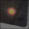
注:カードのスポットサイズはビームパワーによって変化します(右写真参照)。
 Products Home



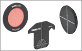

 ズーム
ズーム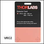

 レーザ用ビュワーカード