 Products Home
レーザー走査顕微鏡用走査レンズ
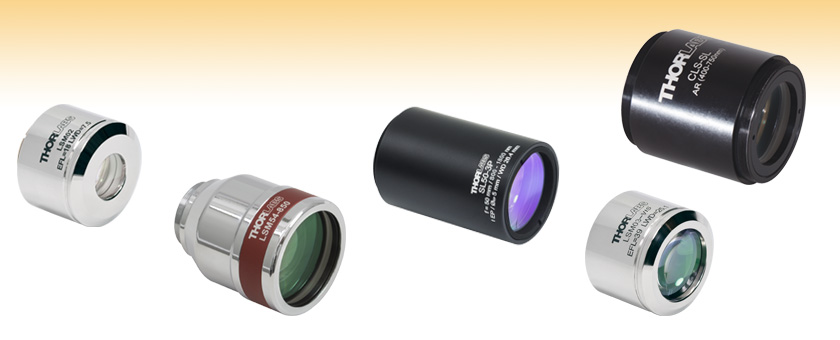
- Telecentric Scanning Lenses with Flat Image Planes
- Minimal Optical Aberrations and Low F-Theta Distortion
- Large Maximum Fields of View up to 28.9 x 28.9 mm2
- Applications Include OCT, Confocal, and Multiphoton Microscopy
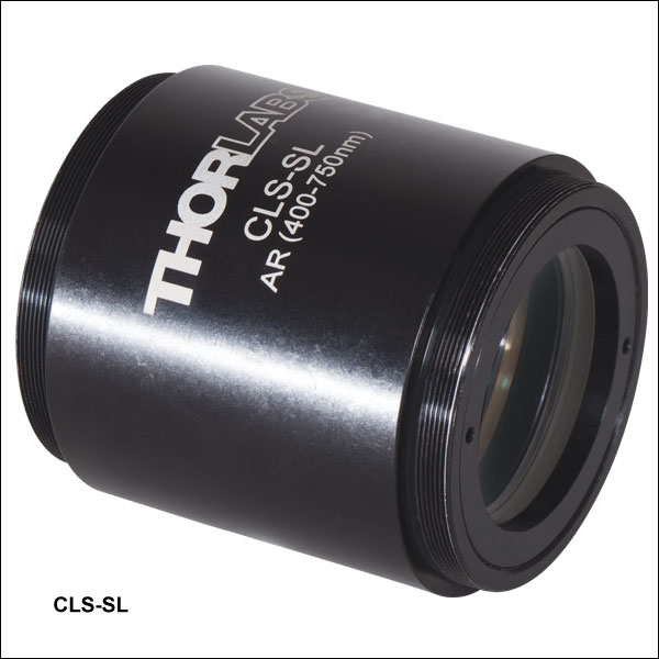
CLS-SL
400 to 750 nm
EFL = 70 mm
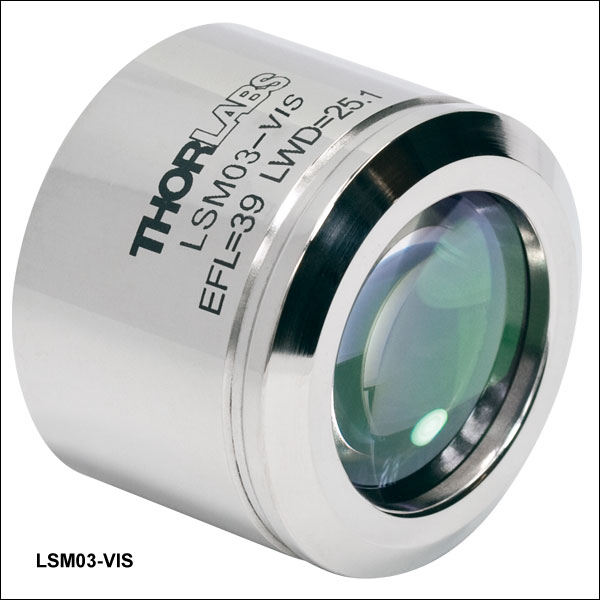
LSM03-VIS
400 to 700 nm
EFL = 39 mm
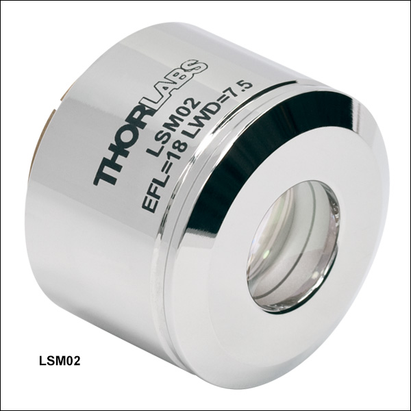
LSM02
1250 to 1380 nm
EFL = 18 mm
SL50-3P
800 to 1800 nm
EFL = 50 mm
LSM54-850
750 to 950 nm
EFL = 54 mm


Please Wait
 Zemaxファイル Zemaxファイル |
|---|
| 下の型番横の赤いアイコン(資料)をクリックするとZemaxファイルをダウンロードいただけます。また、こちらからは当社の全てのZemaxファイルの一括ダウンロードが可能です。 |
特長
- フラットな結像面
- 結像面全体の光学収差を最小限に抑制(詳細は「仕様」タブをご参照ください)
- 広い視野
- 低いf θ歪み
- カスタム仕様の顕微鏡システムに容易に組込み可能
- LSM02(-BB)、LSM03(-BB)、LSM03-VIS、LSM04(-BB)、LSM05(-BB)用の分散補償ブロックあり(別売り)
| Scan Lens Quick Links | |
|---|---|
| Wavelength | Item # |
| 400 to 700 nm | LSM03-VIS |
| 400 to 750 nm | CLS-SL |
| 450 to 1100 nm | SL50-CLS2 |
| 680 to 1300 nm | SL50-2P2 |
| 750 to 950 nm | LSM54-850 |
| 800 to 1100 nm | LSM02-BB, LSM03-BB, LSM04-BB, and LSM05-BB |
| 800 to 1800 nm | SL50-3P |
| 950 to 1100 nm | LSM54-1050 |
| 1200 to 1400 nm | LSM54-1310 |
| 1250 to 1380 nm | LSM02, LSM03, LSM04, and LSM05 |
当社のテレセントリック走査レンズは、光コヒーレンストモグラフィ(OCT)、共焦点顕微鏡、多光子イメージング装置などのレーザ走査イメージングシステム内でのご使用に適しています。 テレセントリック走査レンズにより、フラットな結像面ならびに歪みのほとんどないスポットサイズを得ることができます。これは、光軸に対する入射ビームの角度が変化するためです。入射角が変わることで、焦点は結像面の視野全体を走査することができます。低いf θ歪みが幾何光学的に走査像を補正するため、事後に画像処理をする必要がありません。また、テレセントリック走査レンズは試料から散乱あるいは放出された光(信号)を効率良く検出システムに捕えます。さらに、像面中のスポットサイズは視野全体に渡りほぼ一定となるため(「仕様」タブ参照)、画像の解像度も試料の走査範囲内でほとんど変化しません。
これらの走査レンズの中心波長は可視域~近赤外域となり、様々な有効焦点距離、作動距離ならびに走査距離でご用意しています(詳細は下記および「仕様」タブをご参照ください)。また、これらのレンズの視野は18 × 18 mm2またはそれ以上となり、すべてのレンズには広帯域光源からの後方反射を最小限に抑えるAR(反射防止)コーティングが施されています。
多くの共焦点イメージングシステムは可視域の波長で動作するように設計されており、当社では可視域の走査型共焦点レーザ顕微鏡用に2つの走査レンズ、CLS-SLとSL50-CLS2をご提供しております。SL50-CL2(450~1100 nm)は広い波長範囲にお使いいただけるため、多光子顕微鏡や可視域の光活性化/ターゲティングなどの用途までご使用が可能です。当社では2光子顕微鏡用にSL50-2P2(680~1300 nm)、3光子顕微鏡用にSL50-3P(800~1800 nm)もご用意しております。
近赤外域で動作するシステムには、共焦点、多光子およびOCTの用途向けのものもございます。こちらのページに掲載されているLSMシリーズのレンズはOCTの用途向けに最適化されていますが、共焦点、多光子、およびその他のレーザ走査イメージングシステムにもご使用いただけます。走査レンズLSM54-850、LSM54-1050、LSM54-1310は、6 mmの大きな入射瞳と±14°の走査角度(1軸走査)により、大きな振れ角を生む大型のガルバノミラーと組み合わせて使うのに適しています。さらに走査レンズLSM54-850、LSM54-1050、LSM54-1310はフラットな視野を持ち、200 nmという広い動作波長帯域に渡って色収差を補正します。
当社の走査レンズならびにチューブレンズはそれぞれ個別に収差を補正されています。よってここで紹介する走査レンズはどれも、こちらも収差補正済みのチューブレンズと組み合わせることが可能です。
ご希望のレンズの詳細は、右表内のリンクをクリックまたはページを下の方にスクロールするとご覧いただけます。
仕様
各レンズの詳しい仕様は下表内に記載しています。パラメータの定義については表の下に記載がございます。 表内の青いアイコン![]() をクリックするとグラフがご覧いただけます。
をクリックするとグラフがご覧いただけます。
レンズの波長範囲:400~450 nm以上
| Item # | LSM03-VIS | CLS-SL | SL50-CLS2 | |
|---|---|---|---|---|
| Optical Specifications | ||||
| Wavelength Range | 400 to 700 nm | 400 to 750 nm | 450 to 1100 nm | |
| Effective Focal Length (EFL) | 39 mm | 70.0 mm | 50 mm | |
| Entrance Pupil Diametera | 4 mm | 4 mm | 4 mm | |
| Parfocal Distance | 50.7 mm | - | 77.3 mm | |
| Lens Working Distance | 25.1 mm | 54 mm | 26.4 mm | |
| Scanning Distanceb | 29.0 mm ± 5 mm | 58 ± 6 mm | 37.8 ± 4 mm | |
| Optical Scan Anglec (Single-Axis Scan) | Maximum | ±10.6° | ±11° FN26.9 | ±11.5° |
| Difffraction Limited | ±8.4° (543 nm) | ±10.4° (486 to 750 nm) FN25.5d ±9.4° (400 to 750 nm) FN23d | ±7.5° (at 486.1 nm) ±9° (at 587.6 nm) ±11.5° (656.6 - 1100 nm) | |
| Optical Scan Anglec (Two-Axis Scan) | Maximum | ±7.5° x ±7.5° | ±7.8° x ±7.8° | ±8.1° x ±8.1° |
| Diffraction Limited | ±5.1° x ±5.1° (543 nm) | ±7.35° x ±7.35° (486 to 750 nm) ±6.6° x ±6.6° (400 to 750 nm) | ±5.3° x ±5.3° (at 486.1 nm) ±6.3° x ±6.3° (at 587.6 nm) ±8.1° x ±8.1° (656.6 nm - 1100 nm) | |
| Spot Size Plotsa | Two-Axis Scan:  Single-Axis Scan:  | Single-Axis Scan: | Single-Axis Scan: | |
| Field of Viewe | Maximum | 10.3 x 10.3 mm2 (Two-Axis Scan) | 19 x 19 mm2 FN25.5 (Two-Axis Scan) | 14.1 x 14.1 mm2 FN20 (Two-Axis Scan) |
| Diffraction Limited | 6.9 x 6.9 mm2 | 18 x 18 mm2 FN25.5 (486 to 750 nm) 16 x 16 mm2 FN23 (400 to 750 nm) | 9.2 x 9.2 mm2 FN13 (at 486.1 nm) 11.1 x 11.1 mm2 FN15.7 (at 587.6 nm) 14.1 x 14.1 mm2 FN20 (656.5 - 1100 nm) | |
| Depth of Viewe (Twice Rayleigh Length) | 0.28 mm | - | - | |
| F-Theta Distortione | < 0.8% | < 0.05% | < 0.2% | |
| Field Curvaturee | < 0.3 mm | < 0.7 mm for FN25d < 0.5 mm for FN21d | < 500 µm | |
| Axial Color | 60 µm (400 to 700 nm) | < 50 µm (400 to 750 nm) | < 80 µm for 450 - 1100 nm < 25 µm for 680 - 1100 nm Plot: | |
| Lateral Color Shift | 15 µm (400 to 700 nm) | - | - | |
| f/# | 9.8 | 17.5 | 12.5 | |
| Transmittance | - | |||
| Reflectance |  | - | - | |
| Dimensional Specifications | ||||
| Mounting Thread (External) | M25 x 0.75 | SM2 (2.035"-40), Both Ends | SM30 (M30.5 x 0.5) | |
| Thread Length | 4.4 mm (0.17") | 6.0 mm (0.24") | 3.0 mm (0.12") | |
| Barrel Diameter | 34 mm (1.35") | 56.0 mm (2.20") | 35.0 mm (1.38") | |
| Length of Barrel | 25.5 mm (1.00") | 55.5 mm (2.19") | 50.9 mm (2.00") | |
レンズの波長範囲:680~810 nm以上
| Item # | SL50-2P2 | LSM54-850 | LSM02-BB | LSM03-BB | LSM04-BB | LSM05-BB | |
|---|---|---|---|---|---|---|---|
| Optical Specifications | |||||||
| Wavelength Range | 680 to 1300 nm | 750 to 950 nm | 800 to 1100 nma | ||||
| Effective Focal Length (EFL) | 50 mm | 54 mm | 18 mm | 36 mm | 54 mm | 110 mm | |
| Entrance Pupil Diameterb | 5 mm | 6 mm | 4 mm | 8 mm | |||
| Parfocal Distance | 77.3 mm | 112 mm | 30.7 mm | 50.5 mm | 80.7 mm | 154.8 mm | |
| Lens Working Distance | 26.4 mm | 64 mm | 7.5 mm | 25.1 mm | 42.3 mm | 93.8 mm | |
| Scanning Distancec | 37.8 ± 4 mm | 17.8 mm ± 7.5 mm | 16.1 mm ± 5 mm | 18.9 mm ± 5 mm | 18.9 mm ± 5 mm | 75.5 mm ± 5 mm | |
| Optical Scan Angled (Single-Axis Scan) | Maximum | ±11.5° | ±14.0° | ±10.6° | ±10.6° | ±10.6° | ±10.6° |
| Diffraction Limited | ±7.2° (at 680 nm) ±8° (at 800 nm) ±11.5° (1000 - 1300 nm) | ±13.6° | ±10.2° (850 nm) ±10.6° (1050 nm) | ±9.0° (850 nm) ±9.7° (1050 nm) | ±10.6° (850 nm) ±10.6° (1050 nm) | ±7.2° (850 nm) ±8.1° (1050 nm) | |
| Optical Scan Angled (Two-Axis Scan) | Maximum | ±8.1° x ±8.1° | ±10.0° x ±10.0° | ±7.5° x ±7.5° | ±7.5° x ±7.5° | ±7.5° x ±7.5° | ±7.5° x ±7.5° |
| Diffraction Limited | ±5.3° x ±5.3° (at 680 nm) ±6.3° x ±6.3° (at 800 nm) ±8.1° x ±8.1° (1000 nm - 1300 nm) | ±8.4° x ±8.4° | ±5.1° x ±5.1° (850 nm) ±5.9° x ±5.9° (1050 nm) | ±6.3° x ±6.3° (850 nm) ±6.8° x ±6.8° (1050 nm) | ±7.5° x ±7.5° (850 nm) ±7.5° x ±7.5° (1050 nm) | ±4.9° x ±4.9° (850 nm) ±5.5° x ±5.5° (1050 nm) | |
| Spot Size Plotsb | Single-Axis Scan: | Two-Axis Scan:  Single-Axis Scan: | Two-Axis Scan: 850 nm:  1050 nm:  Single-Axis Scan: 850 nm:  1050 nm:  | Two-Axis Scan: 850 nm:  1050 nm:  Single-Axis Scan: 850 nm:  1050 nm:  | Two-Axis Scan: 850 nm:  1050 nm:  Single-Axis Scan: 850 nm:  1050 nm:  | Two-Axis Scan: 850 nm:  1050 nm:  Single-Axis Scan: 850 nm:  1050 nm:  | |
| Field of Viewe | Maximum | 14.1 x 14.1 mm2 FN20 | 18.8 x 18.8 mm2 (Two-Axis Scan) | 4.7 x 4.7 mm2 (Two-Axis Scan) | 9.4 x 9.4 mm2 (Two-Axis Scan) | 14.1 x 14.1 mm2 (Two-Axis Scan) | 28.9 x 28.9 mm2 (Two-Axis Scan) |
| Diffraction Limited | 8.9 x 8.9 mm2 FN12.6 (at 680 nm) 9.9 x 9.9 mm2 FN14 (at 800 nm) 14.1 x 14.1 mm2 FN20 (1000 - 1300 nm) | 15.8 x15.8 mm2 | 3.2 x 3.2 mm2 (850 nm) 3.7 x 3.7 mm2 (1050 nm) | 7.9 x 7.9 mm2 (850 nm) 8.6 x 8.6 mm2 (1050 nm) | 14.1 x 14.1 mm2 (850 nm) 14.1 x 14.1 mm2 (1050 nm) | 18.8 x 18.8 mm2 (850 nm) 21.1 x 21.1 mm2 (1050 nm) | |
| Depth of Viewe (Twice Rayleigh Length) | - | 0.17 mm | 0.09 mm (850 nm) 0.11 mm (1050 nm) | 0.36 mm (850 nm) 0.45 mm (1050 nm) | 0.81 mm (850 nm) 1.01 mm (1050 nm) | 0.85 mm (850 nm) 1.05 mm (1050 nm) | |
| F-Theta Distortione | < 0.2% | < 0.3% | < 0.9% | < 0.2% | < 1.1% | < 0.4% | |
| Field Curvaturee | < 500 µm | < 0.3 mm | < 0.1 mm | < 0.2 mm | < 0.2 mm | < 0.5 mm | |
| Axial Color | < 25 µm for 680 - 1100 nm Plot: | 210 µm (750 to 950 nm) | 5 µm (810 to 890 nm) 10 µm (1000 to 1100 nm) | 15 µm (810 to 890 nm) 10 µm (1000 to 1100 nm) | 30 µm (810 to 890 nm) 10 µm (1000 to 1100 nm) | 30 µm (810 to 890 nm) 150 µm (1000 to 1100 nm) | |
| Lateral Color Shift | - | 5 µm (750 to 950 nm) | 5 µm (810 to 890 nm) 5 µm (1000 to 1100 nm) | 10 µm (810 to 890 nm) 10 µm (1000 to 1100 nm) | 20 µm (810 to 890 nm) 20 µm (1000 to 1100 nm) | 10 µm (810 to 890 nm) 30 µm (1000 to 1100 nm) | |
| f/# | 12.5 (4 mm Entrance Pupil) 10 (5 mm Entrance Pupil) | 9.0 | 4.5 | 9.0 | 13.5 | 13.8 | |
| Transmittance | - | ||||||
| Reflectance | - | - |  a a | ||||
| Dimensional Specifications | |||||||
| Mounting Thread (External) | SM30 (M30.5 x 0.5) | M25 x 0.75 | M25 x 0.75 | SM2 (2.035"-40) | |||
| Thread Length | 3.0 mm (0.12") | 4.7 mm (0.19") | 4.4 mm (0.17") | 4.5 mm (0.18") | 4.7 mm (0.19") | 5.5 mm (0.22") | |
| Barrel Diameter | 35.0 mm (1.38") | 43.0 mm (1.40") | 33 mm (1.30") | 34 mm (1.35") | 34 mm (1.35") | 59.5 mm (2.34") | |
| Length of Barrel | 50.9 mm (2.00") | 48.0 mm (1.89") | 23.2 mm (0.91") | 25.5 mm (1.00") | 38.25 mm (1.51") | 61.0 mm (2.40") | |
レンズの波長範囲:800~1250 nm以上
| Item # | SL50-3P | LSM54-1050 | LSM54-1310 | LSM02 | LSM03 | LSM04 | LSM05 | |
|---|---|---|---|---|---|---|---|---|
| Optical Specifications | ||||||||
| Wavelength Range | 800 to 1800 nm | 950 to 1150 nm | 1200 to 1400 nm | 1250 to 1380 nm | ||||
| Effective Focal Length | 50 mm | 54 mm | 54 mm | 18 mm | 36 mm | 54 mm | 110 mm | |
| Entrance Pupil Diametera | 5 mm | 6 mm | 6 mm | 4 mm | 4 mm | 4 mm | 8 mm | |
| Parfocal Distance | 77.3 mm | 112 mm | 112 mm | 30.7 mm | 50.6 mm | 80.8 mm | 154.8 mm | |
| Lens Working Distance | 26.4 mm | 64 mm | 64 mm | 7.5 mm | 25.1 mm | 42.3 mm | 93.8 mm | |
| Scanning Distanceb | 37.8 ± 4 mm | 17.8 mm ± 7.5 mm | 17.8 mm ± 7.5 mm | 16.1 mm ± 5 mm | 18.9 mm ± 5 mm | 18.9 mm ± 5 mm | 75.5 mm ± 5 mm | |
| Optical Scan Anglec (Single-Axis Scan) | Maximum | ±11.5° | ±14.0° | ±14.0° | ±10.6° | ±10.6° | ±10.6° | ±10.6° |
| Diffraction Limited | ±8.0° (at 800 nm) ±8.5° (at 900 nm) ±11.5° (1000 - 1800 nm) | ±14.0° | ±14.0° | ±10.6° | ±10.6° | ±10.6° | ±9.0° | |
| Optical Scan Anglec (Two-Axis Scan) | Maximum | ±8.5° x ±8.5° | ±10.0° x ±10.0° | ±10.0° x ±10.0° | ±7.5° x ±7.5° | ±7.5° x ±7.5° | ±7.5° x ±7.5° | ±7.5° x ±7.5° |
| Diffraction Limited | ±6.0° x ±6.0° (at 900 nm) | ±9.5° x ±9.5° | ±10.0° x ±10.0° | ±6.7° x ±6.7° | ±7.4° x ±7.4° | ±7.5° x ±7.5° | ±6.2° x ±6.2° | |
| Spot Size Plotsa | Single-Axis Scan:  | Two-Axis Scan:  Single-Axis Scan:  | Two-Axis Scan:  Single-Axis Scan:  | Two-Axis Scan:  Single-Axis Scan:  | Two-Axis Scan: Single-Axis Scan:  | Two-Axis Scan: Single-Axis Scan:  | Two-Axis Scan: Single-Axis Scan:  | |
| Field of Viewd | Maximum | 14.1 x 14.1 mm2 FN20 | 18.8 x 18.8 mm2 (Two-Axis Scan) | 18.8 x 18.8 mm2 (Two-Axis Scan) | 4.7 x 4.7 mm2 (Two-Axis Scan) | 9.4 x 9.4 mm2 (Two-Axis Scan) | 14.1 x 14.1 mm2 (Two-Axis Scan) | 28.9 x 28.9 mm2 (Two-Axis Scan) |
| Diffraction Limited | 10.5 x 10.5 mm2 FN14.8 (at 900 nm) 14.1 x 14.1 mm2 FN20 (1000 - 1800 nm) | 18.0 x 18.0 mm2 | 18.8 x 18.8 mm2 | 4.2 x 4.2 mm2 | 9.3 x 9.3 mm2 | 14.1 x 14.1 mm2 | 23.8 x 23.8 mm2 | |
| Depth of Viewd (Twice Rayleigh Length) | - | 0.22 mm | 0.27 mm | 0.14 mm | 0.56 mm | 1.26 mm | 1.32 mm | |
| F-Theta Distortiond | < 0.2% | < 0.25% | < 0.25% | < 0.9% | < 0.2% | < 1.1% | < 0.4% | |
| Field Curvature | < 700 µm | < 0.3 mm | < 0.3 mm | < 0.1 mm | < 0.2 mm | < 0.2 mm | < 0.5 mm | |
| Axial Color | < 250 µm (800 to 1800 nm) Plot:  | 50 µm (950 to 1150 nm) | 200 µm (1200 to 1400 nm) | 25 µm (1250 to 1380 nm) | 5 µm (1250 to 1380 nm) | 50 µm (1250 to 1380 nm) | 300 µm (1250 to 1380 nm) | |
| Lateral Color Shift | - | 30 µm (950 to 1150 nm) | 50 µm (1200 to 1400 nm) | 10 µm (1250 to 1380 nm) | 10 µm (1250 to 1380 nm) | 25 µm (1250 to 1380 nm) | 60 µm (1250 to 1380 nm) | |
| f/# | 10 (5 mm Entrance Pupil) | 9.0 | 9.0 | 4.5 | 9.0 | 13.5 | 13.8 | |
| Transmittance | - | |||||||
| Reflectance | - |  | ||||||
| Dimensional Specifications | ||||||||
| Mounting Thread (External) | SM30 (M30.5 x 0.5) | M25 x 0.75 | M25 x 0.75 | M25 x 0.75 | SM2 (2.035"-40) | |||
| Thread Length | 3.0 mm (0.12") | 4.7 mm (0.19") | 4.7 mm (0.19") | 4.4 mm (0.17") | 4.5 mm (0.18") | 4.7 mm (0.19") | 5.5 mm (0.22") | |
| Barrel Diameter | 35.0 mm (1.38") | 43.0 mm (1.40") | 43.0 mm (1.40") | 33 mm (1.30") | 34 mm (1.35") | 34 mm (1.35") | 59.5 mm (2.34") | |
| Length of Barrel | 50.9 mm (2.00") | 48.0 mm (1.89") | 48.0 mm (1.89") | 23.2 mm (0.91") | 25.5 mm (1.00") | 38.25 mm (1.51") | 61.0 mm (2.40") | |
主要パラメータの定義
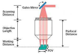
入射瞳(EP)のサイズ:ガルバノミラーを1つだけ使用した場合、入射瞳(EP、後方開口部とも呼ばれます)はミラーの回転軸に位置します。ミラーを2つ使用した場合、EPの位置はミラーとミラーの間になります。EPのサイズによりイメージシステムの分解能が最大になる理想的なコリメート光のビーム径(1/e2で定義)が決定されます。
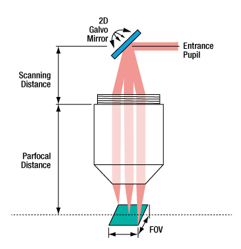
走査距離(SD):SDは、EPがある開口面と、取付けネジのベースとして定義される対物レンズ後方取付け面との間の距離です。これらのレンズの取付け面は、ネジに隣接するレンズのショルダまたはネジ付きマウント面となっています。ガルバノミラーを2つ使用した場合、開口面は2つのミラーの中心部にきます。ガルバノミラーを1つだけ使用した場合、ミラーの回転軸は開口面と一致します。詳細は「使用例」タブをご参照ください。
走査角度(SA):ガルバノミラーを通過したレーザ光は、ガルバノ角に応じた角度でレンズに入射します。このレンズの光軸を基準に測定される角度が、走査角度です。仕様表では、許容走査角度の最大範囲を示しています。
同焦点距離(PD):PDは、走査レンズの取付け面から前側焦点面までの距離です。
作動距離(WDまたはLWD):WDは走査レンズ筐体の先端から前側焦点面までの間の距離です。
視野(FOV):FOVは、走査レンズ仕様に記載された分解能で試料をイメージングできる最大の走査領域です。光学システム内で走査レンズを適切に使用できる範囲を推定します。 動作中、スポット位置はFOV内を走査します。
視野深度(DOV):DOVのパラメータは、前側焦点面におけるビームスポット径よりも、√2倍大きくなる2つの平行面間の距離で定義されます。このパラメータは、OCTでよくみられるようなチューブレンズを光学システムで使用しない場合や、前面の焦点位置が試料面と同じである場合に適用します。チューブレンズを走査レンズと対で使用する場合、結像面は走査レンズとチューブレンズの間に位置します。試料の視野深度は顕微鏡用対物レンズによって制御されます。
スポットサイズのデータ
一般的に、結像面で形成されるスポットの大きさは、OCTシステムの設計に関して、他のレーザ走査顕微鏡システムよりも重視されます。これは、ほとんどのOCTシステムにおいて、結像面が試料面と一致するためです。他の走査用途では、走査レーザは常にチューブレンズと対で使用するため、走査レンズの結像面と試料面は一致しません。
これらのレンズのスポットサイズのグラフは、上の表内の青いアイコン![]() をクリックしてご覧いただけます。スポットサイズのデータを計算して、2軸および1軸走査のシミュレーションすることができます。2軸の場合はガルバノミラーを2つ使用したシステム、1軸の場合はガルバノミラーを1つだけ使用したシステムをシミュレーションできます。開口面にある入射瞳の位置は、使用するミラーが1つか2つかによって変わります。ガルバノミラーを2つ使用した場合、「使用例」タブ内の右側の図のように、開口面は2つのガルバノミラーの中心に位置します。ガルバノミラーを1つだけ使用した場合、「使用例」タブ内の左側の図のように、開口面はミラーの回転軸に位置します。
をクリックしてご覧いただけます。スポットサイズのデータを計算して、2軸および1軸走査のシミュレーションすることができます。2軸の場合はガルバノミラーを2つ使用したシステム、1軸の場合はガルバノミラーを1つだけ使用したシステムをシミュレーションできます。開口面にある入射瞳の位置は、使用するミラーが1つか2つかによって変わります。ガルバノミラーを2つ使用した場合、「使用例」タブ内の右側の図のように、開口面は2つのガルバノミラーの中心に位置します。ガルバノミラーを1つだけ使用した場合、「使用例」タブ内の左側の図のように、開口面はミラーの回転軸に位置します。
2軸走査により、2次元の走査角度範囲全体におけるスポットサイズおよび位置の変化に関する詳細情報を取得できます(結像面全体のスポットサイズがプロットされます)。このデータは単一波長(レンズの中心波長)で計算され、縦軸上にスポットサイズのデータがプロットされた3次元プロットで表示されます。
2次元の1軸走査グラフには以下の3つの曲線が含まれます:中心波長、仕様の最小および最大波長。同時に、スポットサイズの波長依存性も表示されます。1軸走査のグラフには、走査角度の1次元領域におけるスポットサイズおよび位置が表示されます。スポットの位置は結像面を通るライン上を走査します。 2軸および1軸走査のグラフでは、開口面の位置が異なるため、1軸走査のグラフデータは2軸走査のグラフデータの断面図とは完全には一致しません。 1軸走査データはレンズの中心波長に焦点を合わせたシステムを使用してシミュレーションしており、システムは3つの波長全てに合わせてはいません。
走査レンズは共焦点レーザ走査型顕微鏡、光コヒーレンストモグラフィ(OCT)、多光子イメージングシステムほか様々なレーザーイメージングシステムに使用されています。これらの用途では、レンズの後方開口部(入射瞳)から入射したレーザ光が角度走査されます。これにより、レンズの視野内の結像面に形成されたスポットが移動します。テレセントリックレンズ以外のレンズを使用して像面の焦点を走査すると、顕著な収差が引き起こされ、生成画像の画質は著しく損なわれます。テレセントリック走査レンズは、各走査位置において均一なスポットサイズを生成するので、高画質な試料像が得られます。スポットサイズならびに走査位置と走査角度の関係を示したグラフは、「仕様」タブでご覧いただけます。
一般的に、レーザ走査顕微鏡システムは走査レンズとチューブレンズを対で使用し、無限遠補正の光学システムを構築します。しかし多くのOCTシステムは、チューブレンズ無しで走査レンズを使用する設計です。レンズCLS-SL、SL50-CLS2、SL50-2P2そしてSL50-3Pは、当社の共焦点レーザ型走査顕微鏡ならびに多光子顕微鏡システム向け、そしてLSMシリーズのレンズはOCTイメージングシステム向けに最適化されています。走査システムにおけるチューブレンズの有無については後述しています。
Click to Enlarge
上の図は焦点距離が200 mmのテレセントリックチューブレンズと走査レンズSL50-2P2を使用した場合のレンズ間の距離を示しています。なおSL50-CLS2を使用した場合、走査面における入射瞳は最大Ø4 mmとなります。
一般的なレーザ走査顕微鏡に組み込んだ走査レンズ
右の図ではレーザ走査顕微鏡における走査レンズとチューブレンズ間の適切な距離を示しています。図の左側の走査面に位置する走査ミラーは、レーザービームを走査レンズに誘導します。走査レンズへの入射角度により、走査レンズとチューブレンズTTL200MPの間に位置する中間の像面の焦点位置が決まります。チューブレンズは光を収集し、コリメートする位置にあります(無限焦点)。コリメート光は対物レンズを通り、試料面で焦点を結びます。試料面で散乱または放射された光は対物レンズにより集光され、ディテクタに誘導されます。左下の画像では走査レンズCLS-SLをチューブレンズとともに使用しています。画像をクリックするとCLS-SLとチューブレンズITL200を使用した場合の正確なレンズ間の距離がご覧いただけます。
この光学システム設計の特長は、走査レンズとチューブレンズを組み合わせることによってコリメート光が生成されることです。チューブレンズの光が無限遠で集光されるため、チューブレンズに対する対物レンズの位置を移動させても、試料面での画質には影響がありません。 これにより光学システムを高い柔軟性で設計することが可能となります。チューブレンズを使用しない場合、走査レンズは対物レンズと同様に機能し、中間の像面は試料面となります。画質を維持したまま走査レンズに対して像面の位置を大きく動かすことは非常に困難です。
右下では、走査距離とチューブレンズと対物レンズの間の距離の関係性について図で示しています。完全な4f光学系(例としてCLS-SLを使用)において、d1 = 52 mm(最小走査距離)ならびにd2 = f2です。しかし実際のシステムはこの完全なアライメントから若干逸脱しています。例えば多くの市販の顕微鏡では、チューブレンズと対物レンズの間の距離(d2は、焦点距離(f2)と等しくはありません。よって距離の調整が必要になる場合があります。右下の図では走査距離とチューブレンズと対物レンズの間の距離がそれぞれδ1ならびにδ2と少しずつ移動していることを示しています。これらの値の関係性はδd1 = -δd2*(f1/f2)2です。
Click for Details
チューブレンズCLS-SLをITL200と対物レンズとともに組み込んだレーザ走査システム。
Click to Enlarge
一般的なレーザ走査システムでのレンズ配置。
OCTシステムに組み込んだ走査レンズ
LSM走査レンズを使用したOCTイメージングシステムの設計で重要な点ですが、設計波長、同焦点面距離、走査距離、入射瞳寸法や走査角度を考慮して使用すると画質が最大限に向上できます(走査レンズの仕様や用語の定義については「仕様」タブをご参照ください)。 一般的に入射ビーム径が大きくなると焦点サイズは小さくなります。しかし、ビネット効果や収差の増大によりビーム径が大きくなるにつれ、走査角度の範囲は狭くなります。ビーム系が入射瞳寸法より小さい場合スポットサイズは「仕様」タブ内に記載された値よりも大きくなり、逆に径が寸法より大きい場合はビームが蹴られてしまいます。
ガルバノミラーが1つしかないイメージングシステムでは、走査レンズの入射瞳の中心は、ガルバノミラーの回転軸と一致していなければなりません。ガルバノミラーを1つだけ使用する場合、走査距離はレンズの取付け面からミラーの回転軸までの測定距離となります。これは左下の図で示されています。
イメージジングシステム内にガルバノミラーが2つある場合は(1個はX方向の走査用、もう1個がY方向走査用)、右下の図のように入射瞳が2つのガルバノミラーの間に位置する必要があります。この場合、走査距離は、レンズの取付け面からレンズ(d1)に近い方のミラーの回転軸に、このミラーの回転軸から入射瞳までの距離(d2)を加えた値になります。ここで重要なのは2つのガルバノミラーの間の距離を最小とすることです。入射瞳とビームステアリングの回転軸が一致していない場合、画質は劣化します。この現象の主な原因は、試料上を走査するビーム光の光路長のバラツキです。下図はイメージングシステムにおいて、ガルバノミラーが1つの場合と2つの場合を示しています。
ガルバノミラーを1つだけ使用した場合、
入射瞳はミラーの回転軸の位置にきます。
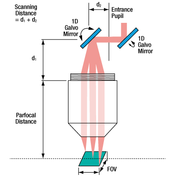
ガルバノミラーを2つ使用した場合、
入射瞳はミラーとミラーの間に位置します。
| Posted Comments: | |
Conner Phillips
(posted 2023-05-25 13:06:23.02) Greetings,
I am wondering how the performance of the LSM03 and other lenses in the line LSM0* line might be expected to perform over the 1450-1690 nm range, primarily regarding transmission and focal length shift. cdolbashian
(posted 2023-06-01 02:31:26.0) Thank you for reaching out to us with these inquiries. While we tightly tolerance these lenses to achieve our listed specs within each lens' respective wavelength range, we do not characterize nor do we test these for wavelengths out of the design wavelength. A s such we cannot give you a certain estimated quality of performance out of the design wavelength range. Jon Daniels
(posted 2023-05-02 09:49:39.543) I'm interested in knowing the *transmission* of LSM03-VIS (not just the reflection). I'm particularly interested in knowing how fast the reflection falls off just outside the rated range. fnero
(posted 2023-05-08 01:59:27.0) Thank you for reaching out to us with your question. In general, transmission and reflection outside the specified range can vary from unit to unit and cannot be guaranteed. We have reached out to you directly to discuss your application more in detail. user
(posted 2022-10-27 14:00:51.047) Could you provide the exact value of the Rayleigh Range for the LSM04 and the LSM03 lens for a wavelength of 1325 nm? cdolbashian
(posted 2022-10-31 01:39:43.0) Thank you for your inquiry! In order to estimate these values, you will need to know your input beam parameters such as divergence angle and beam diameter. We have Zemax Black box files for all of our scan lenses. Please feel free to use these to simulate your expected behavior. user
(posted 2022-08-19 10:46:09.89) Dear Thorlabs,
I have a scan lens SL50-2P2 and plan to develop an OCT system. But it seems the LSM series are the ones to be optimized for OCT systems. What are the drawbacks of using SL50-2P2 for OCT compared with the LMS series? Thank you cdolbashian
(posted 2022-09-26 04:57:22.0) Thank you for reaching out to us with this inquiry. The short answer to this question is that one of these is designed explicitly with OCT in mind, while the other is simply a scan lens which could potentially fill a similar role. I have reached out to you directly with some more explicit answers to your question. user
(posted 2022-01-25 16:35:06.99) Hello
Could you suggest a scanning head that could be use together with lens LSM02?
The issue I am finding is that all galvo systems I have seen cannot have this lens located closer than 15 mm. At this distance, the full field of view of the lens cannot be used as vignetting occurs. Furthermore, the lens is not able to operate in telecentric condition. So, is there a scanning head that is actually compatible with the LSM02 lens?
thank you in advance.
Kind regards.
Diego Omel Mendoza-Yero
(posted 2021-10-19 09:45:24.62) Hello,
I would like to know what is the best configuration for LSM54-850 lens to work in a telecentric scanning mode?
Best regards,
Omel. YLohia
(posted 2021-12-22 04:24:31.0) Please note our application info tab on the scan lens page:
https://www.thorlabs.de/newgrouppage9.cfm?objectgroup_id=2910
For 2D Galvo scanner the LSM objectives cannot provide a strict telecentric beam path for all scan angles.
The dispersion compensator is used in OCT systems within the reference arm. The dispersion compensators are only plan parallel glass blocks. user
(posted 2021-03-26 21:47:03.267) Dear Thorlabs, Which tube lens would you recommend for the LSM54-1050 in a laser scanning application with a 1064 nm source and a 40x/0.8 objective? mdiekmann
(posted 2021-04-07 05:13:50.0) Thank you for contacting us! We have contacted you directly to discuss the details of your application. Marijn Siemons
(posted 2020-08-19 09:50:09.83) Hi!
I have a question about the LSM03-VIS.
What is the transmission of this lens? Most other lenses appear to have a specification for this, but the CLS-SL unfortunately not.
I'm looking forward the answer.
regards,
Marijn YLohia
(posted 2020-09-24 04:04:38.0) Hello Marijn, thank you for contacting Thorlabs. Unfortunately, we do not have transmission information for the LSM03-VIS at the moment. We do, however, offer the reflectance information on this page. We hope to add the transmission data to the website in the future. Christian Maibohm
(posted 2020-07-22 10:32:57.027) Dear Thorlabs,
We would like to use the SL50-CLS2 together with the TTL200MP tube lens for a scanning laser microscope with sub 10 fs pulses. Is it possible to get information regarding the glass thickness and material as well as the second + third order dispersion induced by this lens set?
Thank you in advance, Christian Maibohm asundararaj
(posted 2020-08-17 04:38:37.0) Thank you for contacting Thorlabs. While the glass material and thickness of these components is proprietary, the black box zemax files are available which can be used to estimate performance. I have contacted you about the dispersion info for the SL50-CLS2 via email. Alex Bouhelier
(posted 2020-03-26 05:04:15.337) Hello,
I am looking to retrofit your 2D large beam Galvo system with a NIKON TE 2000 equipped with a high NA objective (60X, NA 1.49, entrance pupil=9 mm). I am considering the telecentric system composed of the tube lens (TL200) and the scan lens (SL50). I have a concern about the entrance pupil of the scan lens (4 mm)n which will severely limit the diameter of the laser beam entering the objective. This will reduce the resolution of the microscope, since the entrance pupil of the objective will be underfilled. What is your recommendation? YLohia
(posted 2020-03-26 10:43:37.0) Hello, thank you for contacting Thorlabs. The final resolution will be limited by the optic that is the weakest link in your optical system. The scan lenses will inherently lower the resolution possible since the beam is scanned through a range of angles over the back aperture (so it is not possible to fully fill the entrance pupil of your objective with the beam). Additionally, the lens design is optimized for flat-field scanning and chromatic performance, but not diffraction limited focus spot size. You may achieve higher resolution by using the LSM05-BB instead, which has a larger entrance pupil diameter, if it falls within your wavelength range. The Spot Size vs Scan Angle plot for this lens can be found in the Specs tab : https://www.thorlabs.com/images/TabImages/LSM05-BB_850nm_Spot_Size_Single_Axis_Scan_A1-800.gif. Enoch Hong
(posted 2020-01-06 21:15:57.12) Is it possible to use this lens directly without any other optical component for coaxial imaging (w/ CCD) and laser scanning? YLohia
(posted 2020-01-09 08:31:55.0) Thank you for contacting Thorlabs. In general, it is possible to use the LSM03-VIS for laser scanning applications. I have reached out to you directly to discuss your specific requirements to determine the suitability of this lens for your application. Eric Yang
(posted 2019-09-23 20:33:29.853) 如果将LSM05-BB应用于激光切割,损伤阈值大概多少? YLohia
(posted 2019-09-23 12:38:48.0) Hello, thank you for contacting Thorlabs. One of our Applications Engineers from our Thorlabs China Group (techsupport-cn@thorlabs.com) will reach out to you directly. x.attendu
(posted 2019-02-14 11:54:00.58) Dear Sir/Madam,
I am wondering if it is possible to implement the SL50-CLS2 in an OCT setup. This lens would be used directly as the scan lens without any other optical component in a setup similar to the ones presented in the 'scan lenses implemented in OCT' in the application info tab. llamb
(posted 2019-02-18 02:56:39.0) Thank you for contacting Thorlabs. In general, you may use the SL50-CLS2 in an OCT setup without other optical components, but your Field of View will be quite truncated. We will reach out to you by email to discuss your application further. benju
(posted 2018-09-24 13:00:48.367) Was there a mistake in the two-axis spot size simulation? It should be rotation symmetric, no? The plot looks more like a square / 4-sided symmetry. YLohia
(posted 2018-09-27 08:31:47.0) Hello, thank you for contacting Thorlabs. The plot is based on a two-galvo-scanning system with a certain mirror separation. That causes the rectangular scan area and the symmetry characteristic. The reason for the shown symmetry is the moving aperture plane position for different x & y image coordinates, and the different aberrations for that aperture position. akbar.khodaei
(posted 2018-03-03 10:57:03.457) Hi,
What makes such huge price difference between TTL200MP and TL200-CLS2?
If the difference in scan angel makes this price difference, how much is the maximum scan angle of each of them?
Thanks. nbayconich
(posted 2018-04-24 03:26:46.0) Thank you for contacting Thorlabs. Both of these tube lenses have identical performance in terms of field of view, the ±11mm FOV for TTL200MP is the radial field of view (22mm diameter circle) which translates to a 16.3mm x 16.3mm square field of view. The working distance and AR coating will be slightly different between these two lenses and the high cost comes from the lens material used in the TTL200-CLS2. In terms of performance the TTL200MP will perform just as well as the TTL200-CS. matz.liebel
(posted 2017-08-16 16:00:56.873) Same question as mcravenc I am looking for the Zemax blackbox (mirrored and normal) files for:
LSM03-VIS
Maybe you could just upload them here so the next person doesn't have to post again. tfrisch
(posted 2017-08-28 10:37:38.0) Hello, thank you for contacting Thorlabs. For now, I will reach out to you directly with the reverse file, and the forward version is already posted on the web. I'll talk to our design and marketing teams about posting them. mcravenc
(posted 2016-12-06 12:16:50.693) Please provide the mirror space Zemax blackbox files for the LSM54-1050 and the LSM54-850. This would be enormously helpful to microscope design. Without the mirror space blackbox file, users cannot model confocal or two-photon microscopes. tfrisch
(posted 2016-12-06 01:32:40.0) Hello, thank you for contacting Thorlabs. I will reach out to you directly about these Zemax files. ludoangot
(posted 2016-09-19 11:01:59.59) Hello, can these lenses be used for non-scanning imaging? I mean by this to use them to directly obtain an image of a sample on a camera sensor plane rather than scanning a laser beam on the sample. What would be the drawback(s) in doing so (maybe the spot size and the chromatic aberration)? jlow
(posted 2016-09-20 03:46:51.0) Response from Jeremy at Thorlabs: There are a few main concerns for imaging with these objectives. The chromatic correction is not optimized for visible region. The AR coatings (except for the two visible ones) are not optimized for visible region. These lens are also telecentric so it offers no depth perspective your samples. mikhail.mazurenka
(posted 2016-04-21 13:45:31.207) Dear Sir or Madam
Could you please tell me the NA of the LSM03 lens.
Best regards,
Mikhail besembeson
(posted 2016-04-21 02:00:09.0) Response from Bweh at Thorlabs USA: You can't really define the NA of a scan lens. You could look at this in multiple ways. If you are looking at the input to the lens from a scanning mirror, then you may use the scan angle of 7.5deg to determine a numerical aperture but this will be beam diameter dependent. At the image side, you could use the effective focal and the ideal collimated beam diameter (or pupil size) of 4mm to estimate a numerical aperture. loic.morvan
(posted 2015-12-03 13:49:22.8) Hello,
we would like to interface one of the LSM04-BB, on the angle scanning side (threaded), to a vacuum box.
To this aim, we would like to know :
- the material and thickness of the last element on the angle scan side,
- if it is possible to dismantle the threaded part in order to add something to make it hermetic.
Additionally, we work at a specific wavelength. would it be possible to have a custom version with an AR coating optimized to this wavelength, to minimize ghosts ?
do not hesitate to contact me directly by email.
Many thanks besembeson
(posted 2015-12-03 11:09:02.0) Response from Bweh at Thorlabs USA: Thanks for contacting Thorlabs. I will follow up with you to discuss your application further and provide the special quotation. nmorel
(posted 2015-11-09 11:23:11.473) Can you tell me the material for LSM02-BB? smcelwee
(posted 2015-11-12 05:32:35.0) Response from Sean M at Thorlabs USA: Thank you for your feedback. I will contact you directly to get details about your application and provide the material information. valdemar.s
(posted 2015-08-10 01:36:32.03) Dear to whom ir concern,
We are interested on laser scanning application for laser microfabrication with your scan lens CLS-SL, tube lens ITL200 and LSM03-VIS objective.
Would it be acceptable to use these components with picosecond up to 5 W averagepower laser. What is maximum allowable damage threshold for these optical components?
Best regards,
Valdemar Stankevič
Engineer & Project manager besembeson
(posted 2015-09-29 05:35:49.0) Response from Bweh at Thorlabs USA: We don't have these damage threshold values for these lenses. I will follow-up to determine if your peak powers can still be okay for these components. thomas.liebig
(posted 2015-06-01 11:33:12.02) Dear sir/madam,
the zemax file of LSM05-BB seems to be the one of LSM05. Eventhough it is named correctly, after opening the title of the lens is LSM05 and the wavelength specified is 1315nm insted of the BBs 850nm & 1050nm. I would like to receive the correct ZMX file rather soon if possible.
Sincerely
Thomas Liebig myanakas
(posted 2015-06-12 11:30:11.0) Response from Mike at Thorlabs: Thank you for your feedback. The LSM05 and LSM05-BB are the same with exception to the coating. We are working on updating the Zemax files to include the different coating. However, in the meantime, the wavelength can be changed within the file by going to “System” and then “Wavelength Data”. papour
(posted 2015-03-27 11:42:32.067) The LSM04 was shipped in a plastic bag- this is not ideal for lenses in general. Would be better to get it in a plastic rigid box such that the lens surfaces are better protected (as most objective lenses are stored and shipped). besembeson
(posted 2015-04-03 03:07:44.0) Response from Bweh at Thorlabs USA: Thanks for the feedback. We will review our packaging process for these to protect the lens surface better. If your unit came with any scratches, we will replace this for you. user
(posted 2015-03-16 01:35:28.853) "The shorter the distance between the tube lens and the objective, the longer the scanning position."
What is meant by "scanning position" in this statement? Isn't the scanning position determined by the working distance of the objective lens? myanakas
(posted 2015-03-23 12:56:25.0) Response from Mike at Thorlabs: Thank you for your feedback. The scanning position is defined as the distance from the scanning mirror to the end of the externally threaded region on the scan lens housing. This can be seen in the “Application info” tab or in the enlarged image in the “Visible Scan Lens for Laser Scanning Microscopy” grouping. In a 4f optics system the distance from the tube lens to the objective will be f2, or the focal length of the tube lens. However, this is rarely the case in an imaging system. When the objective is moved from this position the scan lens will also have to shift to compensate for this. When the objective is moved further from the tube lens the scanning position will decrease, and vice versa. We are currently working on updating this presentation to make this more clear. jessie.weber
(posted 2014-07-22 15:38:10.96) On the Specs tab in the "Scan Lenses for Laser Scanning Microscopy" page, the mean spot size for this lens is reported in the table "1315 nm OCT Scan Lenses" as 23.5um. However, in the graphs tab, the spot sizes shown for 1315nm are 65-67um. Is this an error? Could you confirm the mean spot size for this lens?
Thank you. myanakas
(posted 2014-07-23 09:23:47.0) Response from Mike at Thorlabs: Thank you for your feedback. The mean spot size in the table within the “Specs” tab is valid for an entrance beam diameter of 8 mm. The graph is showing the spot size for a single mode fiber that is being collimated with an asphere. This provides an entrance beam diameter of approximately 4 mm. Both mean spot sizes are correct, but they are for different entrance beam diameters. We will update the website to make this more clear. jason.tan
(posted 2014-02-26 16:04:28.157) Hi
I have had a question, is LSM03 can replace the ITL200?
(I want the low EFL tube lens(EFL> 100mm).
what do you suggest ?
thanks for paying attention. besembeson
(posted 2014-02-28 04:47:36.0) Response from Bweh E at Thorlabs: Thanks for contacting Thorlabs. The LSM03 is generally used in laser imaging system and scanning applications. The ITL200 is typically used for camera imaging in conjunction with an objective. These are the optimal ways of using these components. I will send you separate email to discuss your application further so that we can decide on optimal components for you. mgg6
(posted 2013-09-05 23:30:06.82) The zemax model files for the LSM03-BB and LSM03 are identical (same MD5sum). Is this correct and the two products are actually identical optically aside from the AR coating, or were the wrong model files uploaded? sharrell
(posted 2013-09-06 11:10:00.0) Response from Sean at Thorlabs: Thank you for using our feedback form. These two lenses are identical except for the coating. Since the coating information was not included in the Zemax files, the models are identical. sharrell
(posted 2012-08-16 08:42:00.0) Response from Sean at Thorlabs: Thank you for your feedback. I am sorry that these files have been unavailable. We are in the process of updating our website with the .zar files for these products, which is what we now use as the standard provided format. These files will be available on the web later today, and I have sent you the files for the requested products directly. loic.morvan
(posted 2012-08-16 08:23:19.0) Hello,
Im interested in having the zemax models (even in "black box" form) for LM02-BB, LM03-BB, LM004-BB and LM-05BB.
Thank you by advance bdada
(posted 2012-02-06 14:55:00.0) Response from Buki at Thorlabs:
Thank you for participating in our feedback forum. We are looking into your request and will contact you with more information. anup.katake
(posted 2012-02-03 13:28:23.0) Hello,
To incorporate the LSM-02 lens in the design, will it be possible for you to send the zemax design file for it?
Also, what would happen if I use the lens at 1550nm?
Thanks bdada
(posted 2011-07-21 13:49:00.0) Response from Buki at Thorlabs:
We do not currently offer the scan lenses designed for visible wavelengths. We have contacted you to learn more about your application and to see if another of our objective lenses could be suitable for your application. bdada
(posted 2011-07-21 13:43:00.0) Response from Buki at Thorlabs:
Thank you for your feedback. Please review the excerpt below that is in the write up in the "Application Info" tab:
"It is important to minimize the distance between the two galvo mirrors, because when the entrance pupil and beam steering pivot point are not coincident, the quality of the image is degraded. This is principally due to the variation in the optical path length as the beam is scanned over the sample."
Please contact TechSupport@thorlabs.com if you have further questions concerning this or if you want to discuss your application. user
(posted 2011-07-21 11:08:22.0) In the "Application Info" I can read this: "The maximum recommended separation between the two
galvo mirrors is 8 mm." Why is there a maximum separation? Thank you. ykpark76
(posted 2011-07-20 22:30:45.0) Can I use these Scan lenses at visible range?
Or Can you make a Scan lens for visible range?
(For example, 530nm ~ 700nm) bdada
(posted 2011-04-14 10:01:00.0) Response from Buki at Thorlabs to Edgar:
Thank you for your feedback. We have contacted you with the Zemax black box files. Please contact TechSupport@thorlabs.com if you have further questions. edgar.guevara
(posted 2011-04-12 16:08:02.0) Could you post the full ZEMAX data (.zmx) for LSM04? I think it would be very useful for all the users who want to optimize the spot
profiles over the entire scanning range. boris.povazay
(posted 2010-11-26 07:24:49.0) Would it be possible to indicate the focal lengths, versus scanning angle also for the 800 +/- 150 and 1060 +/-70nm range? (or even better the focal shift versus wavelength for a set of angles/object sizes)
Are designs with a wider field of view (~50mm) planned.
Best regards! |

 ズーム
ズーム| Key Specificationsa,b | |
|---|---|
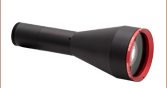
| Wavelength Range | 400 to 700 nm |
| Effective Focal Length | 39 mm |
| Lens Working Distance | 25.1 mm |
| Field of View, Maximum | 10.3 x 10.3 mm2 |
| Field of View, Diffraction Limited | 6.9 x 6.9 mm2 |
| Spot Size Plot, 543 nm (Two-Axis Scan) | |
| Reflectance | |
| Mounting Threads (External) | M25 x 0.75 |
- 仕様の詳細については「仕様」のタブをご参照ください。
- 表内の青いアイコン
 をクリックするとグラフがご覧いただけます。
- OCTイメージングシステム用に最適化
- 入射瞳:4 mm
- 走査角度範囲:±10.6°(最大、単軸)
- M25 x 0.75外ネジ
こちらのレンズは、OCTイメージング用に最適化されていますが、幅広いレーザ走査顕微鏡の用途にご使用いただけます。走査レンズLSM03-VISは、可視域(400~700 nm)でのイメージング用に設計、ARコーティングがされています。このレンズの主な特長は右の表に記載されています。詳しい仕様については「仕様」タブをご参照ください。
M25 × 0.75外ネジは、アダプタSM1A12を使用して当社の標準的なSM1シリーズ規格のネジに変換することができます。また、アダプタRMSA2によって走査レンズをRMSネジ付き部品と一緒にご使用いただくことができます。
OCTイメージングシステムにこちらの走査レンズを対物レンズとして使用する場合には、分散補償器LSM03DC-VISをご用意しております。

 ズーム
ズーム| Key Specificationsa,b | |
|---|---|
| Wavelength Range | 400 to 750 nm |
| Effective Focal Length | 70.0 mm |
| Lens Working Distance | 54 mm |
| Field of View, Maximum | 19 x 19 mm2 |
| Field of View, Diffraction Limited | 18 x 18 mm2 (486 to 750 nm) 16 x 16 mm2 (400 to 750 nm) |
| Spot Size Plot: 405, 436, 486, 587, 633, and 750 nm |  |
| Transmittance | |
| Mounting Threads (External) | SM2 (2.035"-40) |
- 仕様の詳細については「仕様」のタブをご参照ください。
- 表内の青いアイコンをクリックするとグラフがご覧いただけます。
- 共焦点顕微鏡システム用に最適化
- 入射瞳:4 mm
- 広視野:最大19 x 19 mm2
- SM2外ネジ
走査レンズCLS-SLは、可視域(400~750 nm)におけるpoint-by-pointのレーザ走査イメージング用途向けに設計、ARコーティングされています。こちらのレンズは、当社の共焦点顕微鏡システム用に設計されていますが、両側にあるSM2外ネジを使用してお客様独自のレーザ走査システムに簡単に組み込むことができます。チューブレンズITL200および当社の対物レンズと組み合わせてご使用いただくことをお勧めいたします。
なおCLS-SLの筐体は対称的な形状ですが、双方向性はありません。筐体の刻印が正しい向きにある場合に、光はレンズの上側から入射させます。仕様の詳細については「仕様」タブをご参照ください。

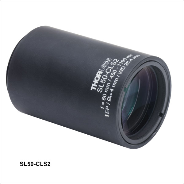 ズーム
ズーム| Key Specificationsa,b | |
|---|---|
| Wavelength Range | 450 to 1100 nm |
| Effective Focal Length | 50 mm |
| Lens Working Distance | 26.4 mm |
| Field of View, Diffraction Limited | 9.2 x 9.2 mm2 (486.1 nm) 11.1 x 11.1 mm2 (587.6 nm) 14.1 x 14.1 mm2 (656.6 -1100 nm) |
| Transmittance | |
| Mounting Threads (External) | SM30 (M30.5 x 0.5) |
- 仕様の詳細については「仕様」のタブをご参照ください。
- 表内の青いアイコンをクリックするとグラフがご覧いただけます。
- レーザ走査顕微鏡システム用に最適化
- チューブレンズTTL200MPと使用する場合はテレセントリックレンズとして機能
- 入射瞳:4 mm
- 広視野:656.6~1100 nmでは最大14.1 x 14.1 mm2
- SM30外ネジ
走査レンズSL50-CLS2は、可視域および近赤外域(450~1100 nm)におけるpoint-by-pointのレーザ走査イメージング用途向けに設計、ARコーティングされています。広い波長範囲にお使いいただけるので、多光子顕微鏡や可視域の光活性化/ターゲティングなどの用途までご使用が可能です。この走査レンズは、一端に付いているSM30外ネジを使用して自作のシステムに簡単に組み込むことができます。SM30内ネジ&SM1外ネジ付きアダプタSM1A70(下記参照)を用いると、このレンズをガルバノスキャンヘッドLSK-GG4/M、LSK-GR08/M、または LSK-GR12/Mの出射ポートから正しい距離に配置することができます。また、SM30-SM2変換アダプタSM2A11を使用すると、当社のSM2レンズチューブに取り付けることができます。このレンズは、チューブレンズTTL200MPと対物レンズを組み合わせて使用すると、テレセントリックレンズとしてお使いいただける設計です(「使用例」タブ内の図をご参照ください)。
筐体には、「EP」(入射瞳)の文字の横に矢印が刻印されています。この矢印が指す側を走査システムに向けてください。

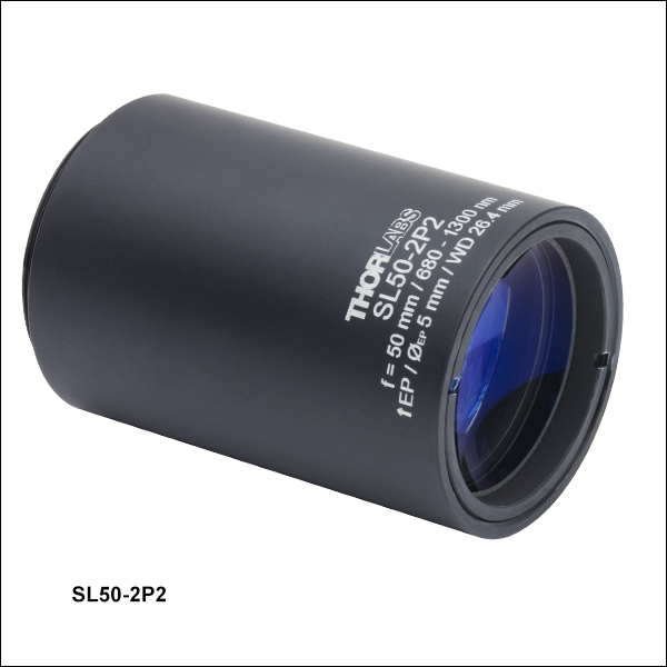 ズーム
ズーム| Key Specificationsa,b | |
|---|---|
| Wavelength Range | 680 to 1300 nm |
| Effective Focal Length | 50 mm |
| Lens Working Distance | 26.4 mm |
| Field of View, Diffraction Limited | 8.9 x 8.9 mm2 (680 nm) 9.9 x 9.9 mm2 (800 nm) 14.1 x 14.1 mm2 (1000 - 1300 nm) |
| Transmittance | |
| Mounting Threads (External) | SM30 (M30.5 x 0.5) |
- 仕様の詳細については「仕様」のタブをご参照ください。
- 表内の青いアイコンをクリックするとグラフがご覧いただけます。
- レーザ走査顕微鏡システム用に最適化
- チューブレンズTTL200MPと使用する場合はテレセントリックレンズとして機能
- 入射瞳:5 mm
- 広視野:1000~1100 nmでは最大14.1 x 14.1 mm2
- SM30外ネジ
走査レンズSL50-2P2は、近赤外域(680~1600 nm)におけるpoint-by-pointのレーザ走査イメージング用途向けに設計、ARコーティングされています。この走査レンズは当社のBergamo® IIシリーズ多光子顕微鏡で使用されており、一端に付いているSM30外ネジを使用して自作のシステムに簡単に組み込むことができます。SM30内ネジ&SM1外ネジ付きアダプタSM1A70(下記参照)を用いると、このレンズをガルバノスキャンヘッドLSK-GG4/M、LSK-GR08/M、または LSK-GR12/Mの出射ポートから正しい距離に配置することができます。また、SM30-SM2変換アダプタSM2A11を使用すると、当社のSM2レンズチューブに取り付けることができます。このレンズは、チューブレンズTTL200MPと対物レンズを組み合わせて使用すると、テレセントリックレンズとしてお使いいただける設計です(「使用例」タブ内の図をご参照ください)。
筐体には、「EP」(入射瞳)の文字の横に矢印が刻印されています。この矢印が指す側を走査システムに向けてください。

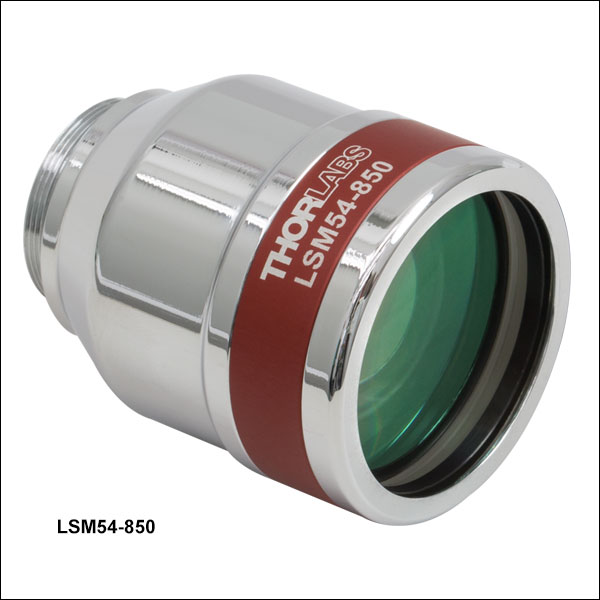 ズーム
ズーム| Key Specificationsa,b | |
|---|---|
| Wavelength Range | 750 to 950 nm |
| Effective Focal Length | 54 mm |
| Lens Working Distance | 64 mm |
| Field of View, Maximum | 18.8 x 18.8 mm2 |
| Field of View, Diffraction Limited | 15.8 x 15.8 mm2 |
| Spot Size Plot, 850 nm (Two-Axis Scan) | |
| Transmittance | |
| Mounting Threads (External) | M25 x 0.75 |
- 仕様の詳細については「仕様」のタブをご参照ください。
- 表内の青いアイコンをクリックするとグラフがご覧いただけます。
- OCTイメージングシステム用に最適化
- 入射瞳:6 mm
- 走査角度範囲:±14.0°(最大、単軸)
- 広視野:最大18.8 x 18.8 mm2
- 最小スポットサイズ:850 nmにおいて14 µm(右の表参照)
レンズLSM54-850は、OCTイメージング用に最適化されていますが、幅広いレーザ走査顕微鏡の用途にご使用いただけます。レンズLSM54は、当社の多くのLSMシリーズ走査レンズよりも入射瞳が大きく、走査角度範囲が広いため、大型でより大きな振れ角を生むガルバノミラーとの使用に適しています。光学設計を最適化して屈折素子をより多く使用することにより、色収差補正や、幅広いスペクトル域への対応を実現しました。動作波長範囲が950~1150 nmまたは1200~1400 nmのシステムでは、それぞれレンズLSM54-1050とLSM54-1310を使用することで同様の性能を得ることができます。
右の表には、レンズLSM54-850の主な仕様を記載しています。波長850 nmにおける像面上のスポットサイズの細かさやスポットの位置(代表値)を走査角度ごとに示したグラフもご覧いただけます。スポットサイズや透過率のグラフは、青いアイコン![]() をクリックするとご覧いただけます。仕様の詳細については「仕様」タブをご参照ください。
をクリックするとご覧いただけます。仕様の詳細については「仕様」タブをご参照ください。
M25 × 0.75外ネジは、アダプタSM1A12を使用して当社の標準的なSM1シリーズ規格のネジに変換することができます。また、アダプタRMSA2によって走査レンズをRMSネジ付き部品と一緒にご使用いただくことができます。
OCTイメージングシステムにこちらの走査レンズを対物レンズとして使用する場合には、分散補償器LSM54DC1 をご用意しております。

 ズーム
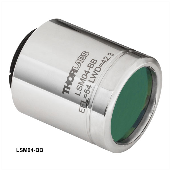
ズーム| Key Specificationsa,b | ||||
|---|---|---|---|---|
| Item # | LSM02-BB | LSM03-BB | LSM04-BB | LSM05-BB |
| Wavelength Range | 800 to 1100 nm | |||
| Effective Focal Length | 18 mm | 36 mm | 54 mm | 110 mm |
| Lens Working Distance | 7.5 mm | 25 mm | 42 mm | 94 mm |
| Field of View, Maximum | 4.7 x 4.7 mm2 | 9.4 x 9.4 mm2 | 14.1 x 14.1 mm2 | 28.9 x 28.9 mm2 |
| Field of View, Diffraction Limited | 3.2 x 3.2 mm2 (850 nm) 3.7 x 3.7 mm2 (1050 nm) | 7.9 x 7.9 mm2 (850 nm) 8.6 x 8.6 mm2 (1050 nm) | 14.1 x 14.1 mm2 (850 nm) 14.1 x 14.1 mm2 (1050 nm) | 18.8 x 18.8 mm2 (850 nm) 21.1 x 21.1 mm2 (1050 nm) |
| Spot Size Plot, 850 nm (Two-Axis Scan) | | | | |
| Spot Size Plot, 1050 nm (Two-Axis Scan) | | | | |
| Reflectance | c | |||
| Mounting Threads (External) | M25 x 0.75 | SM2 (2.035"-40) | ||
| Dispersion Compensator | LSM02DC | LSM03DC | LSM04DC | LSM05DC |
| Storage Cased | Lid: OC2M25 Canister: OC22 | N/A | ||
- 仕様の詳細については「仕様」のタブをご参照ください。
- 表内の青いアイコンをクリックするとグラフがご覧いただけます。
- ARコーティングは850 nmと1050 nm付近で最適化されていますが、こちらのレンズは、800 nm~1100 nmの動作範囲内で帯域幅100 nm以下のOCTシステムでの使用に適しています。
- 別売りでご用意
- OCTイメージングシステム用に最適化
- 中心波長:850および1050 nm
- 走査角度範囲:±10.6°(最大、単軸)
- 有効焦点距離は18~110 mmでラインナップ
こちらのレンズは、OCTイメージング用に最適化されていますが、幅広いレーザ走査顕微鏡の用途にご使用いただけます。レンズの性能は、OCT用の一般的な2種類の波長である850 nmおよび1050 nm近傍の波長に最適化されています。仕様の詳細については「仕様」タブをご参照ください。
M25 × 0.75外ネジは、アダプタSM1A12を使用して当社の標準的なSM1シリーズ規格のネジに変換することができます。また、アダプタRMSA2によって走査レンズをRMSネジ付き部品と一緒にご使用いただくことができます。
OCTイメージングシステムにこちらの走査レンズを対物レンズとして使用する場合には、それぞれの走査レンズに合った分散補償器をご用意しております。詳細は右表をご覧ください。
注:レンズLSM0xおよびLSM0x-BBのZemaxファイルにはコーティングの情報が含まれておりません。そのため、型番末尾が-BBであってもZemaxファイルは同じです。

 ズーム
ズーム| Key Specificationsa,b | |
|---|---|
| Wavelength Range | 800 to 1800 nm |
| Effective Focal Length | 50 mm |
| Lens Working Distance | 26.4 mm |
| Field of View, Diffraction Limited | 9.9 x 9.9 mm2 (800 nm) 10.5 x 10.5 mm2 (900 nm) 14.1 x 14.1 mm2 (1000 - 1800 nm) |
| Transmittancec | |
| Mounting Threads (External) | SM30 (M30.5 x 0.5) |
- 仕様の詳細については「仕様」のタブをご参照ください。
- 表内の青いアイコン をクリックするとグラフがご覧いただけます。
- この走査レンズの性能データを含むエクセルファイルはこちらからダウンロードいただけます。
- 3光子レーザ走査顕微鏡システムに対応
- 入射瞳:最大5 mm
- 広視野:1000~1800 nmでは最大14.1 x 14.1 mm2
- SM30外ネジ
走査レンズSL50-3Pは、近赤外域(900~1900 nm)におけるpoint-by-pointのレーザ走査イメージング用途向けに設計、ARコーティングされています。この走査レンズはBergamo®多光子顕微鏡に対応し、一端に付いているSM30外ネジを使用して自作のシステムに簡単に組み込むことができます。SM30内ネジ&SM1外ネジ付きアダプタSM1A70(下記参照)を用いると、このレンズをガルバノスキャンヘッドLSK-GG4/M、LSK-GR08/M、または LSK-GR12/Mの出射ポートから正しい距離に配置することができます。また、SM30-SM2変換アダプタSM2A11を使用すると、当社のSM2レンズチューブに取り付けることができます。走査レンズとチューブレンズの組み合せの詳細については「使用方法」のタブをご覧ください。
筐体には、「EP」(入射瞳)の文字の横に矢印が刻印されています。この矢印が指す側を走査システムに向けてください。

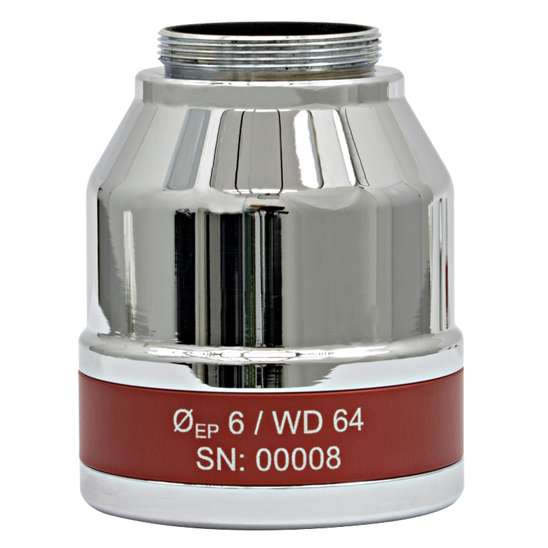
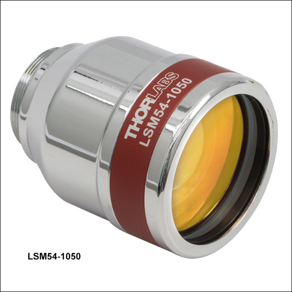 ズーム
ズーム| Key Specificationsa,b | |
|---|---|
| Wavelength Range | 950 to 1150 nm |
| Effective Focal Length | 54 mm |
| Lens Working Distance | 64 mm |
| Field of View, Maximum | 18.8 x 18.8 mm2 |
| Field of View, Diffraction Limited | 18.0 x 18.0 mm2 |
| Spot Size Plot, 1050 nm (Two-Axis Scan) | |
| Transmittance | |
| Mounting Threads (External) | M25 x 0.75 |
- 仕様の詳細については「仕様」のタブをご参照ください。
- 表内の青いアイコンをクリックするとグラフがご覧いただけます。
- OCTイメージングシステム用に最適化
- 入射瞳:6 mm
- 走査角度範囲:±14.0°(最大、単軸)
- 広視野:最大18.8 x 18.8 mm2
- 最小スポットサイズ:1050 nmにおいて18 µm(右の表参照)
レンズLSM54-1050は、OCTイメージング用に最適化されていますが、幅広いレーザ走査顕微鏡の用途にご使用いただけます。レンズLSM54は、当社の多くのLSMシリーズ走査レンズよりも入射瞳が大きく、走査角度範囲が広いため、大型でより大きな振れ角を生むガルバノミラーとの使用に適しています。光学設計を最適化して屈折素子をより多く使用することにより、色収差補正や、幅広いスペクトル域への対応を実現しました。動作波長範囲が750~850 nmまたは1200~1400 nmのシステムでは、それぞれレンズLSM54-850とLSM54-1310を使用することで同様の性能を得ることができます。
右の表には、レンズLSM54-1050の主な仕様を記載しています。波長1050 nmにおける像面上のスポットサイズの細かさやスポットの位置(代表値)を走査角度ごとに示したグラフもご覧いただけます。スポットサイズや透過率のグラフは、青いアイコン![]() をクリックするとご覧いただけます。仕様の詳細については「仕様」タブをご参照ください。
をクリックするとご覧いただけます。仕様の詳細については「仕様」タブをご参照ください。
M25 × 0.75外ネジは、アダプタSM1A12を使用して当社の標準的なSM1シリーズ規格のネジに変換することができます。また、アダプタRMSA2によって走査レンズをRMSネジ付き部品と一緒にご使用いただくことができます。
OCTイメージングシステムにこちらの走査レンズを対物レンズとして使用する場合には、分散補償器LSM54DC2をご用意しております。

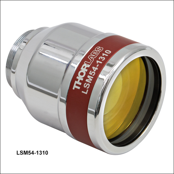 ズーム
ズーム| Key Specificationsa,b | |
|---|---|
| Wavelength Range | 1200 to 1400 nm |
| Effective Focal Length | 54 mm |
| Lens Working Distance | 64 mm |
| Field of View, Maximum | 18.8 x 18.8 mm2 |
| Field of View, Diffraction Limited | 18.8 x 18.8 mm2 |
| Spot Size Plot, 1300 nm (Two-Axis Scan) | |
| Transmittance | |
| Mounting Threads (External) | M25 x 0.75 |
- 仕様の詳細については「仕様」のタブをご参照ください。
- 表内の青いアイコンをクリックするとグラフがご覧いただけます。

- OCTイメージングシステム用に最適化
- 入射瞳:6 mm
- 走査角度範囲:±14.0°(最大、単軸)
- 広視野:最大18.8 x 18.8 mm2
- 最小スポットサイズ:1300 nmにおいて22 µm(右の表参照)
レンズLSM54-1310は、OCTイメージング用に最適化されていますが、幅広いレーザ走査顕微鏡の用途にご使用いただけます。レンズLSM54は、当社の多くのLSMシリーズ走査レンズよりも入射瞳が大きく、走査角度範囲が広いため、大型でより大きな振れ角を生むガルバノミラーとの使用に適しています。光学設計を最適化して屈折素子をより多く使用することにより、色収差補正や、幅広いスペクトル域への対応を実現しました。動作波長範囲が750~850 nmまたは950~1150 nmのシステムでは、それぞれレンズLSM54-850とLSM54-1050を使用することで同様の性能を得ることができます。
右の表には、レンズLSM54-1310の主な仕様を記載しています。波長1310 nmにおける像面上のスポットサイズの細かさやスポットの位置(代表値)を走査角度ごとに示したグラフもご覧いただけます。スポットサイズや透過率のグラフは、青いアイコン![]() をクリックするとご覧いただけます。仕様の詳細については「仕様」タブをご参照ください。
をクリックするとご覧いただけます。仕様の詳細については「仕様」タブをご参照ください。
M25 × 0.75外ネジは、アダプタSM1A12を使用して当社の標準的なSM1シリーズ規格のネジに変換することができます。また、アダプタRMSA2によって走査レンズをRMSネジ付き部品と一緒にご使用いただくことができます。
OCTイメージングシステムにこちらの走査レンズを対物レンズとして使用する場合には、分散補償器LSM54DC3をご用意しております。

 ズーム
ズーム| Key Specificationsa,b | ||||
|---|---|---|---|---|
| Item # | LSM02 | LSM03 | LSM04 | LSM05 |
| Wavelength Range | 1250 to 1380 nm | |||
| Effective Focal Length | 18 mm | 36 mm | 54 mm | 110 mm |
| Lens Working Distance | 7.5 mm | 25.1 mm | 42.3 mm | 93.8 mm |
| Field of View, Maximum | 4.7 x 4.7 mm2 | 9.4 x 9.4 mm2 | 14.1 x 14.1 mm2 | 28.9 x 28.9 mm2 |
| Field of View, Diffraction Limited | 4.2 x 4.2 mm2 | 9.3 x 9.3 mm2 | 14.1 x 14.1 mm2 | 23.8 x 23.8 mm2 |
| Spot Size Plot, 1315 nm (Two-Axis Scan) | |  | | |
| Mounting Threads (External) | M25 x 0.75 | SM2 (2.035"-40) | ||
| Dispersion Compensator | LSM02DC | LSM03DC | LSM04DC | LSM05DC |
| Storage Casec | Lid: OC2M25 Canister: OC22 | N/A | ||
- 仕様の詳細については「仕様」のタブをご参照ください。
- 表内の青いアイコンをクリックするとグラフがご覧いただけます。
- 別売りでご用意
- OCTイメージングシステム用に最適化
- 入射瞳:4 mm
- 走査角度範囲:±10.6°(最大、単軸)
- 複数の有効焦点距離をラインナップ
- M25 x 0.75外ネジ
こちらのレンズは、OCTイメージング用に最適化されていますが、幅広いレーザ走査顕微鏡の用途にご使用いただけます。走査レンズLSM02、LSM03、LSM04、LSM05は、近赤外域1315 nm近傍でのイメージング用に設計、ARコーティングがされています。
右の表内の青いアイコン![]() をクリックすると、垂直および水平の走査方向のスポットサイズ(代表値)のグラフがご覧いただけます。 仕様の詳細については「仕様」タブをご参照ください。
をクリックすると、垂直および水平の走査方向のスポットサイズ(代表値)のグラフがご覧いただけます。 仕様の詳細については「仕様」タブをご参照ください。
M25 × 0.75外ネジは、アダプタSM1A12を使用して当社の標準的なsm1シリーズ規格のネジに変換することができます。また、アダプタ RMSA2によって走査レンズをRMSネジ付き部品と一緒にご使用いただくことができます。
OCTイメージングシステムにこちらの走査レンズを対物レンズとして使用する場合には、それぞれの走査レンズに合った分散補償器をご用意しております。詳細は右表をご覧ください。

 ズーム
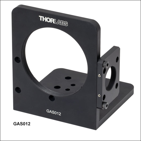
ズーム| Mounting Bracket Item # | GAS012 |
|---|---|
| Thread Adapter Item # | GAS0123 |
| Compatible Scan Lens | LSM05 |
| Compatible Galvo Mirror System | GVS012 or GVS012/M |
| Assembled System Photo (Click for Details) | 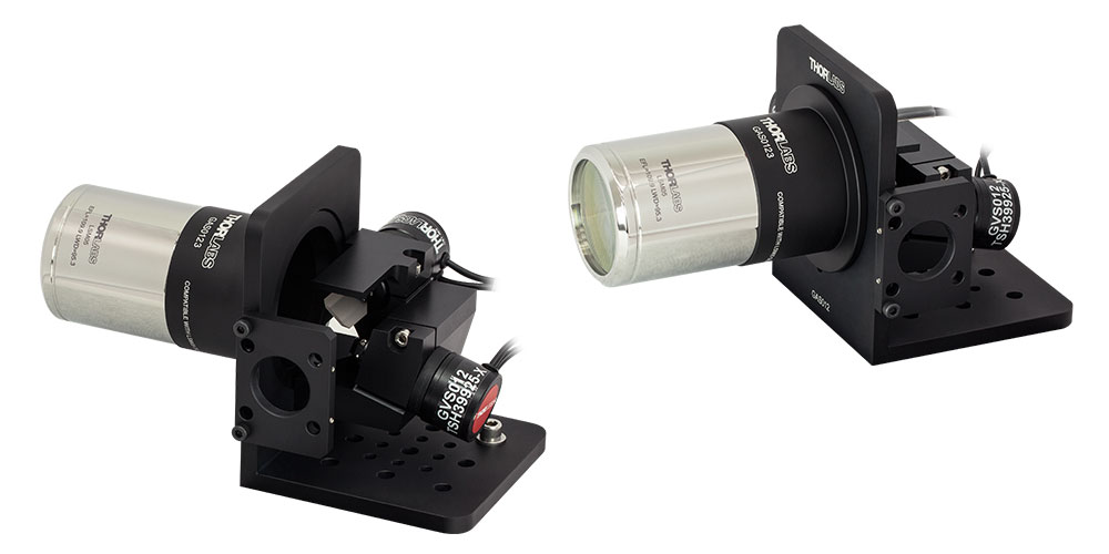 |
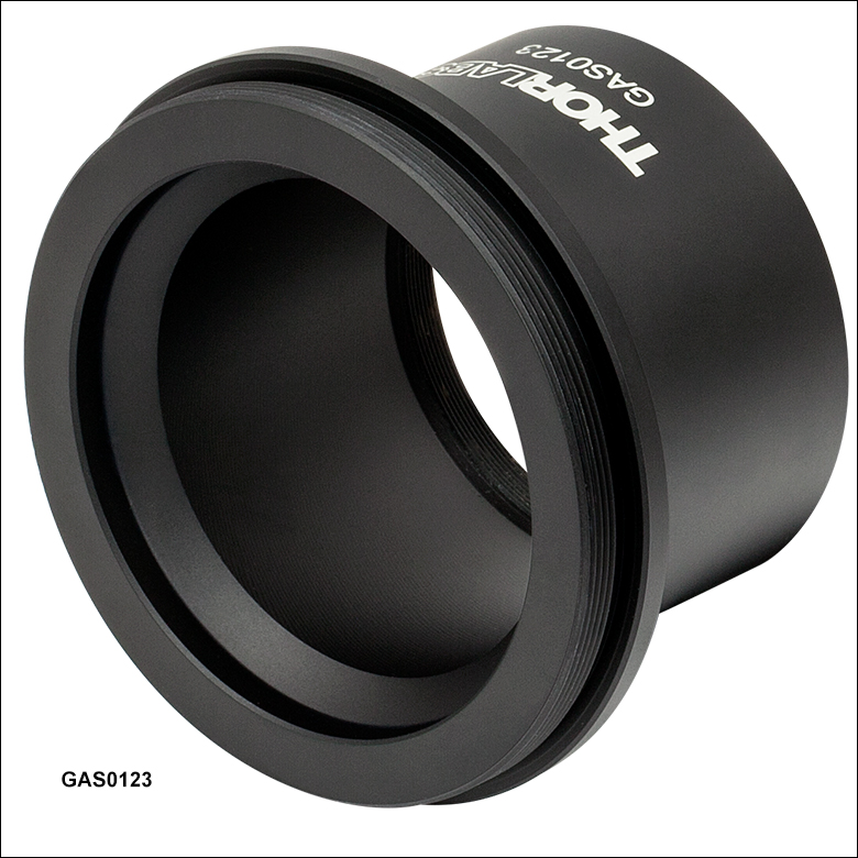
- テレセントリック走査レンズLSM05と大径ビーム用走査型ガルバノミラーシステムGVS012/Mを組み合わせるための取付けブラケットとアダプタ
- 走査レンズLSM05を取付けるためにはネジアダプタGAS0123(下記掲載)が必要です。
- 取り外し可能の入力プレートは30 mmケージシステムならびにSM1ネジシリーズ製品に取付け可能
- ミリ規格およびインチ規格のいずれのブレッドボードや光学テーブルにも取付け可能
GAS012は、テレセントリック走査レンズLSM05と大径ビーム用走査型ガルバノミラーシステムGVS012/Mを組み合わせるための取付けブラケットです。 この取付けブラケットを使用すると、光学テーブルやブレッドボードで構築されたオプトメカニクスシステムにも組み込めます。 取付けブラケットGAS012を使用して走査レンズを取り付けるには、ネジアダプタGAS0123(下記掲載)が必要です。 このネジアダプタにより走査レンズを2枚目のガルバノミラーから推奨距離の位置に配置することができます。
光入力ポートにあるSM1ネジ切り加工によってØ25 mm~Ø25.4 mm(Ø1インチ)レンズチューブに取付けられます。また、Ø6 mmのケージロッド用の穴が4つ付いているので30 mmケージシステムに組み込むこともできます。 GAS012は底面が取付け面になっており、12.6 mm間隔で開けられたM4貫通穴が8つ、25.2 mm間隔で開けられたM6貫通穴が9つあるので、ミリ規格ならびにインチ規格両方のブレッドボードや光学テーブルに対応します。 ガルバノミラーGVS012/Mはこの底面に直接取付けないため、貫通穴はすべて光学テーブルやブレッドボードの取付けに使用できます。

 ズーム
ズーム
Click for Details
GCM102(/M)の図面
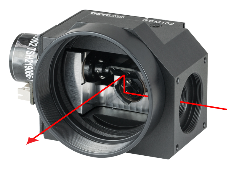
Click to Enlarge
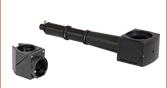
入力ポートから入射し、2枚のガルバノミラーで反射されて、SM2ネジ付き出力ポートから出射されるビームの経路
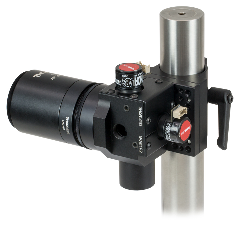
- 2次元ガルバノシステムのポスト、30 mmケージシステム、または66 mmレールキャリッジへの取り付け
- 入力ポートはSM05内ネジならびにSM1内ネジ付き
- 出力ポートはSM2内ネジ付き
- 当社の走査レンズのラインナップに対応(対応する走査レンズについては下の表をご覧ください)
GCM102/Mには、全ての2軸小径ビームガルバノミラーシステムを取り付けることができます。ガルバノシステムをこのマウントに取り付けると、下の写真のようにポスト、30 mmケージシステム、あるいは66 mm光学レールキャリッジに取り付けることができます。
マウントのSM2内ネジ付きの出力ポートには、適切なアダプタを使用することで、走査レンズをガルバノミラーから適切な走査距離の位置に取り付けることが可能です。詳細については下の表をご覧ください。入力ポートにはSM05内ネジならびにSM1内ネジが付いており、Ø12 mm~Ø12.7 mm(Ø1/2インチ)とØ25 mm~Ø25.4 mm(Ø1インチ)レンズチューブが直接取り付けられます。さらに入力ポートの周りにある4つの#4-40タップ穴により 30 mmケージシステムに取り付け可能です。 各ポートに当社のレンズチューブ、ポート用プラグ、そして走査レンズを組み合わせた場合、システム全体が遮光されます。入力ポートと出力ポートの中心は、それぞれX軸とY軸のガルバノミラーの位置にきます。このように入力光と出力光は異なる平面内にあることにご留意ください。
マウントの底部にはM6タップ穴が2つ、M4タップ穴が3つ、そしてM3タップ穴が2つあります。各取付け穴は下の写真のように、ポストクランプアダプタC1511(/M)とC1545(/M)、Ø12 mm、Ø12.7 mm、Ø25 mm、Ø38 mm(Ø1.5インチ)ポスト、そしてレールキャリッジXT66P2(/M)ならびにXT66RCを取り付けられるよう配置されています。 様々な取付けオプションの詳細についてはマニュアルのセクション3.3をご覧ください。
X軸とY軸のガルバノミラーはユニット側面ならびに背面の2つの貫通穴を用いて取り付けます。付属の2 mm六角レンチでフレクシャークランプを動かして、ガルバノミラーの位置を固定します。取り付けに際しては、ミラーの上にあるSM05ネジ付きのビューポートをご利用できます。また、フレクシャークランプへのアクセスにはM6貫通穴2つを利用します。GCM102/Mの上面にあるSM05ネジポートとM6貫通穴は、それぞれプラグSM05PLとM6止めネジ(セットスクリュ)を取付けることで、システムの遮光を維持できます。ガルバノミラーの取り付け方法の詳細はマニュアルのセクション3.1をご覧ください。


Click to Enlarge
走査レンズLSM02を付けて、66 mmレールに取り付けたGCM102(/M)
Click to Enlarge
走査レンズCLS-SLを付けて、Ø38 mm(Ø1.5インチ)ポストに取り付けたGCM102(/M)
| Scan Lens Compatibilitya | |||
|---|---|---|---|
| Item # | Scanning Distanceb | Lens Mounting Thread | Required Adapterb |
| LSM02(-BB) | 16.1 mm ± 5 mm | External M25 x 0.75 | GCMA1 |
| LSM54-850 | 17.8 mm ± 7.5 mm | SM2A33 | |
| LSM54-1050 | |||
| LSM54-1310 | |||
| LSM03(-BB) | 18.9 mm ± 5 mm | GCMA1c | |
| LSM04(-BB) | |||
| LSM03-VIS | 29.0 mm ± 5 mm | SM2A33 and SM2L03 | |
| SL50-CLS2 | 37.8 ± 4 mm | External SM30 (M30.5 x 0.5) | SM2A11 and SM2V05 |
| SL50-2P2 | |||
| LSM05(-BB) | 75.5 mm ± 5 mm | External SM2 (2.035"-40) | SM2L20 |
| CLS-SL | 58 ± 6 mm | SM2L05 and SM2V05 | |

 ズーム
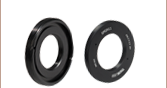
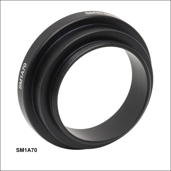
ズーム- SM30内ネジには、SL50シリーズ走査レンズの取付が可能
- SM1外ネジにより、ガルバノ-ガルバノおよびガルバノ-レゾナント走査ヘッドへの取付けが可能
アダプタSM1A70を使用して、走査レンズSL50-CLS2、SL50-2P2またはSL50-3Pを走査ヘッドLSKGGR/M、LSK-GR08/M、またはLSK-GR12/Mの出射ポートに取付けると、走査レンズは走査ミラーから正しい位置(距離)に固定されます。このアダプタにはSM1外ネジとSM30内ネジが付いています。