 Products Home
光電子増倍管モジュール(PMT)
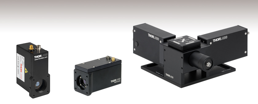
- Several Models Cover 185 - 920 nm Wavelength Range
- Alkali and GaAsP Photocathodes Available
- SM1 or C-Mount Threads for Filters or Lens Tubes
- Models Designed for Single- and Multi-Channel
Detection
PMM02
300 - 800 nm
Multialkali, Standalone
PMT2101
300 - 720 nm
GaAsP, Standalone
PMTSS2
185 - 900 nm
Multialkali, Two Channels


Please Wait
Click to Enlarge
Click for Logarithmic Plot
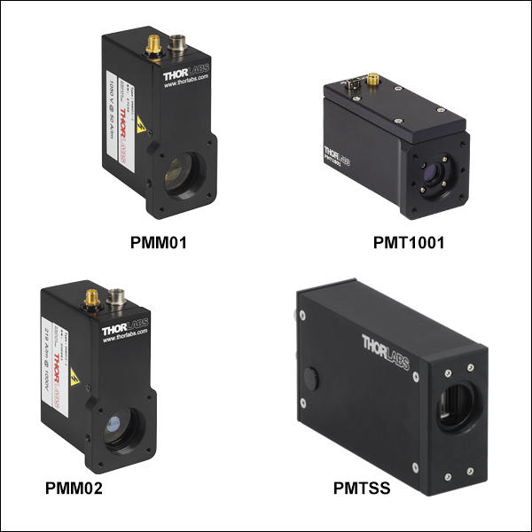
グラフは当社PMTモジュールの典型的な放射感度を示しています。PMT2101/Mおよび PMT2102はもっとも高い放射感度を示しますが、高輝度照明の劣化の影響をもっとも受けやすくなっています。PMM01、PMM02、PMT1001(/M)、PMT1002、PMT2101(/M)、PMT2102には、セットアップに組み込みやすいようトランスインピーダンスアンプが内蔵されています。PMM01、PMM02、PMT1001(/M)、PMT2101(/M)にはSM1内ネジと4つの#4-40タップ穴も付いているため、SM1レンズチューブや30 mmケージシステムに直接取り付けられます。
特長
- 185 nm~920 nm用のバイアルカリ、マルチアルカリおよびGaAsPディテクタ
- 放射感度(典型値):ピーク波長で51 mA/W~176 mA/W(右のグラフ参照)
- 筐体に応じて様々な取付け方法をご用意(「セレクションガイド」タブ参照)
- レンズチューブまたはフィルタ取付け用のSM1またはCマウントネジ
- ポスト取付け用#8-32またはM6タップ穴
- テーブル取付け用M6ザグリ穴スロット
- 30 mmケージシステム用#4-40タップ穴が4つ
- トランスインピーダンスアンプ内蔵のモデルあり
- モジュールPMTSS2は拡張可能なマルチチャンネルシステムの構築用として設計
- Windows®7または10(64ビット)対応ソフトウェア(「ソフトウェア」のタブ参照)
光電子増倍管モジュール(PMT)は、微弱な放射光源からのかすかな光信号を検出するのに使用されます。アバランシェディテクタ(APD)と比較して検出部が非常に大きいため、散乱や非線形効果により拡散する光を捉えるのに適しています。これらのPMTは、Windows®7または10(64ビット)対応で、利得、オフセット電圧、そして帯域幅調整用GUI付きソフトウェアパッケージ(付属)により制御します。ソフトウェアパッケージには、.NET、C++、LabVIEWドライバが含まれています。
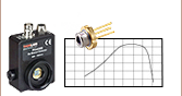
当社では、UV、可視、近赤外域に感度があるアルカリやGaAsPの検出素子を使用したPMTをご用意しています。その性能はどれくらいの入射光子が光電子に変換されるかを示す量子効率(%)で数値化できます。量子効率と放射感度(mA/W)の関係は、下表の脚注bの式で表わされます。当社のPMTの放射感度は右のグラフでご覧いただけます。
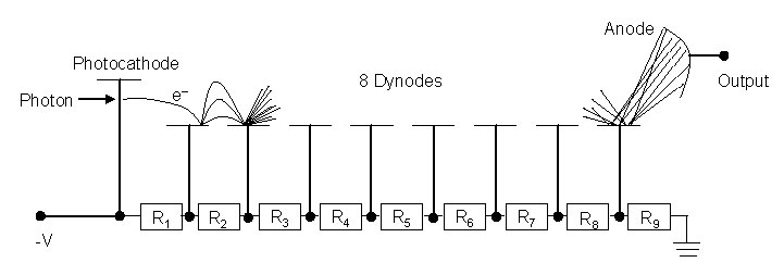
高い内部利得を得るために、PMTの光電陰極で生成された電子はkVオーダの高い電圧により加速され、さらに2次電子を生成する数段のダイノードに衝突します。最終段のダイノードを通過するまで蓄積された光電流は、増幅された信号としてアノードに集められます(詳細については「PMTチュートリアル」タブをご覧ください)。すべてのPMTモジュールには高電圧回路が内蔵されているため、個別に高電圧電源を用意する必要はなく、それによりパッケージの設置面積と感電のリスクも抑制できます。
アノードに集められた光電流は通常トランスインピーダンスアンプに送られ、電圧に変換されると同時に増幅も行われます。モジュールPMM01、PMM02、PMT1001/M、PMT1002、PMT2101/M、PMT2102にはトランスインピーダンスアンプが内蔵されていて、電圧信号が必要な実験装置に直接接続できます。一方でPMTSS、PMTSS2、PMTSS2-SCMにはアンプは内蔵されていません。これらは、当社のトランスインピーダンスアンプTIA60や、別売りのそのほかのトランスインピーダンスアンプにも対応します。
| PMT Comparisona | Standalone | Multi-Channel | ||||
|---|---|---|---|---|---|---|
| Item # | PMM01 | PMM02 | PMTSS | PMT1001(/M) PMT1002 | PMT2101(/M) PMT2102 | PMTSS2 PMTSS2-SCM |
| Photocathode Material | Bialkali | Multialkali | Multialkali | Multialkali | GaAsP | Multialkali |
| Wavelength Range | 280 - 630 nm | 300 - 800 nm | 185 - 900 nm | 230 - 920 nm | 300 - 720 nm | 185 - 900 nm |
| Radiant Sensitivityb (Typ.) | 80 mA/W (at 400 nm) | 51 mA/W (at 420 nm) | 105 mA/W (at 450 nm) | 78 mA/W (at 630 nm) | 176 mA/W (at 550 nm) | 105 mA/W (at 450 nm) |
| Photocathode Active Area | Ø22 mm | Ø21 mm | 3.7 mm x 13.0 mm (H x V) | Ø8 mm | Ø5 mm | 3.7 mm x 13.0 mm (H x V) |
| Transimpedance Amplifier |  | | Not Included (Compatible with TIA60) | | | Not Included (Compatible with TIA60) |
| ||||||
単独型アルカリPMT
| Item # | PMM01 | PMM02 | PMTSS | PMT1001(/M) | PMT1002 |
|---|---|---|---|---|---|
| Detector Specifications | |||||
| Wavelength Range | 280 - 630 nm | 300 - 800 nm | 185 - 900 nm | 230 - 920 nm | |
| Peak Wavelength (λp) | 400 nm | 420 nm | 450 nm | 630 nm | |
| Radiant Sensitivity at λpa (Typ.) | 80 mA/W | 51 mA/W | 105 mA/W | 78 mA/W | |
| Quantum Efficiency at λpa (Calculated from Radiant Sensitivity) | 25% | 15% | > 28% | > 15% | |
| PMT Gain (Max) | 7.1 x 10⁶ | 5.1 x 10⁵ | > 1.0 x 10⁷ See Graphs Tab for PMT Gain vs. Control Voltage | > 3.0 × 10⁶ See Graphs Tab for PMT Gain vs. Control Voltage | |
| HV Control Voltage (Max) | 0 V to +1.8 Vb | 0 V to +1.25 Vb | +0.25 V to +1.00 V (Recommended) +0.25 V to +1.20 V (Maxc) | +0.50 V to +1.10 V Software Controlled | |
| Control Voltage Connector | 2.5 mm Mono Jack | M8 x 1 Power Connector | USB Mini | ||
| PMT Voltage | 0 V to -1800 Vb,d | 0 V to -1250 Vb,d | +250 V to +1000 V (Recommended) +250 V to +1200 V (Maxc) | +500 V to +1100 V | |
| Photocathode Active Area | Ø22 mm | Ø21 mm | 3.7 mm x 13.0 mm (H x V) | Ø8 mm | |
| Dark Currente | 0.3 - 3 nA (at 20 °C) | 3 nA (Typ.) 20 nA (Max) (After 30-Minute Storage in Darkness) | 2 nA (Typ.) 10 nA (Max) | 10 nA (Typ.) 100 nA (Max) | |
| Dark Count Ratee | 100 s-1 (at 20 °C) | - | - | - | |
| Warm-Up Time Before Applying Control Voltagee | < 10 s | 30 to 60 Minutes | 30 to 60 Minutes | ||
| Anode Currentf | 100 µA (Max)g | 10 µAh | 100 µAh | ||
| Rise and Fall Time | 15 µs | 1.4 ns | 0.57 ns (Rise)i | ||
| Photocathode Type | Bialkali | Multialkali | Multialkali | Multialkali | |
| Photocathode Geometry | Head On | Side On | Head On | ||
| Window | Borosilicate, Plano-Concave (n = 1.49) | UV-Transmitting Glass (n = 1.48) | Borosilicate, Flat Window (n = 1.487) | ||
| Transimpedance Amplifier Specifications | |||||
| Transimpedance Gain | High Z: 1 x 10⁶ V/A 50 Ω: 5 x 10⁵ V/A | No Amplifier Included | 11000 +1000 / -500 V/A | ||
| Amplifier Bandwidth (at 6 dB)j | DC to 20 kHz | N/A | Software Configurable DC to 80 MHz, 2.5 MHz, or 250 kHz | ||
| Amplifier Noise (Typ.) | 2 mV (RMS) | N/A | 5.8 pA / √Hz (Total Input Noise at DC to 80 MHz Bandwidth) 6.5 pA / √Hz (Input Current Noise at 1 MHz, Cin = 4 pF) | ||
| Amplifier Offset (Typ.) | 1 mV | N/A | ±103 µV / °Ck | ||
| Output Signall | |||||
| Output Voltage | 0 - 10 V (High Z) 0 - 5 V (50 Ω) | N/A | ±1.5 V (50 Ω) | ||
| Output Current | N/A | 10 µA (Max) | N/A | ||
| Connector | SMA | BNC | SMA | ||
| Physical Specifications | |||||
| Module Dimensions | 3.65" x 1.60" x 2.46" (92.8 mm x 40.6 mm x 62.5 mm) | 5.20" x 1.26" x 2.50" (132.0 x 32.1 x 63.5 mm) | 3.43” x 1.60” x 2.10” (87.2 mm x 40.6 mm x 53.5 mm) | 3.32" x 1.35" x 1.95" (84.4 mm x 34.3 mm x 49.6 mm) | |
| Power Input | +12 V Pin: 40 mA Max, +12 V to +15 V -12 V Pin: 10 mA Max, -12 V to -15 V | 15 VDC, 7 mA Max | 5 VDC +4.5 V to +5.5 V 350 mA Typ., 500 mA Max | ||
| Included Power Supply | ±12 VDC (100/120/230 VAC, 50 or 60 Hz, Switchable)m | - | - | ||
| Operating Temperature | 5 to 55 °C | 15 to 40 °C | 5 to 50 °C | ||
| Storage Temperature | -40 to 55 °C | -20 to 50 °C | -20 to 50 °C | ||
| Module Weight | 200 g (0.44 lbs) | 200 g (0.44 lbs) | 0.3 kg (0.66 lbs) | 300 g (0.66 lbs) | |
| Mounting Options | |||||
| Internal SM1 Threads | (In Front of Window) | (In Front of Window) | - | (In Front of Window) | - |
| Internal C-Mount Threads | - | - | (In Front of Window) | - | (In Front of Window) |
| Mounting Holes | Three 8-32 Taps (8-32 to M4 Adapter Included) | Three 8-32 Taps (8-32 to M4 Adapter Included) | - | 1/4"-20 (M6) Tap | - |
| 30 mm Cage System | (Four 4-40 Taps) | (Four 4-40 Taps) | - | (Four 4-40 Taps) | - |
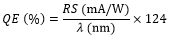
- 放射感度(RS)と量子効率(QE)の関係性は下記の式で表せます。
- PMTの最大出力電圧は超えないでください。
- PMTは最大+1.2 Vの制御電圧で駆動可能です。推奨する制御電圧以上ではPMTの動作寿命を下げる可能性があります。
- PMT電圧 = -1000 × HV Controlの式で求めた値です。
- 暗電流とダークカウントの仕様値は光がない状態でPMTの電源を入れ、規定のウォームアップ時間内で制御電圧の印加や光信号の入射が行われないときに有効です。
- 予期しないスパイク信号によりアノード電流が仕様値を超えないようPMTを周辺光から遮断し、制御電圧も慎重に選択する必要があります。
- アノード電流の最大値を超えるとPMTに修復不可能なダメージを与えます。
- この値を超えると、出力信号は非線形性を示します。
- これらのPMTの立ち下がり時間は規定されていません。
- 出力信号が大きくなると帯域幅が減少します。
- DCドリフト電圧
- 飽和防止のため、出力信号を最大値以下に維持する必要があります。 NDフィルタを、SM1またはCマウントネジを使用して入射窓の前に取り付けることにより、PMTに到達する前に光信号を減衰させることができます。
- 交換用電源を別途ご用意しております(下記参照)。
GaAsP PMT
| Item # | PMT2101(/M) | PMT2102 |
|---|---|---|
| Detector Specifications | ||
| Wavelength Range | 300 - 720 nm | |
| Peak Wavelength (λp) | 580 nm | |
| Radiant Sensitivitya (Typ.) | 176 mA/W at 550 nm | |
| 108 mA/W at 420 nm | ||
| Quantum Efficiencya (Calculated from Radiant Sensitivity) | 39% at 550 nm (Typical)b | |
| 32% at 420 nm (Typical)b | ||
| PMT Gain (Max) | >1.0 × 10⁶ | |
| Control Voltage | +0.50 V to +0.80 V (Recommended) +0.5 V to +1.0 V (Maxc) Software Controlled | |
| Control Voltage Connector | USB Mini | |
| PMT Voltage | +500 V to +800 V (Recommended) +500 V to +1000 V (Max) | |
| Photocathode Active Area | Ø5 mm | |
| Dark Count Rated, e | 6000 s-1 (at 25 °C, Typical) 18000 s-1 (at 25 °C, Maximum) | |
| Warm-Up Time Before Applying Control Voltagee | 30 to 60 minutes (at 25 °C) | |
| Anode Currentf | 500 µA (Max) | |
| Rise Timeg | 1.00 ns | |
| Photocathode Type | GaAsP | |
| Photocathode Geometry | Head On | |
| Window | Borosilicate, Flat Window | |
| Transimpedance Amplifier Specifications | ||
| Transimpedance Gain | 11000 +1000 / -500 V/A | |
| Amplifier Bandwidth (at 6 dB)h,i | Software Configurable DC to 80 MHz, 2.5 MHz, or 250 kHz | |
| Amplifier Noisei (Typ.) | 5.8 pA / √Hz (Total Input Noise at DC to 80 MHz Bandwidth) 6.5 pA / √Hz (Input Current Noise at 1 MHz, Cin = 4 pF) | |
| Amplifier DC Offset Drift (Typ.) | ±103 µV / °C | |
| Maximum Inputj | ±500 μA | |
| Output Signalk | ||
| Output Voltage | ±1.5 V (50 Ω) | |
| Output Current | N/A | |
| Connector | SMA | |
| Physical Specifications | ||
| Module Dimensions | 3.43” × 1.60” × 2.10” (87.2 × 40.6 × 53.5 mm) | 3.32" × 1.35" × 1.95" (84.4 × 34.3 × 49.6 mm |
| Power Input | 5 VDC (+4.5 V to +5.5 V) 350 mA Typ., 500 mA Max | |
| Operating Temperature | 5 to 35 °C | |
| Storage Temperature | -20 to 50 °C | |
| Module Weight | 300 g (0.66 lb) | |
| Mounting Options | ||
| Internal SM1 Threads | (In Front of Window) | - |
| Internal C-Mount Threads | - | (In Front of Window) |
| Mounting Holes | 1/4"-20 (M6) Tap | - |
| 30 mm Cage System | (Four 4-40 Taps) | - |
- 放射感度(RS)と量子効率(QE)の関係性は下記の式で表せます。
- 量子効率はPMTにより異なる場合があります。
- このPMTは最大+1.0 Vの制御電圧で駆動可能です。推奨する制御電圧以上ではPMTの動作寿命を下げる可能性があります。
- 暗室に30分格納後測定された値です。
- ダークカウントの仕様値は光がない状態でPMTの電源を入れ、規定のウォームアップ時間内で制御電圧の印加や光信号の入射が行われないときに有効です。
- 予期しないスパイク信号によりアノード電流が仕様値を超えないようPMTを周辺光から遮断し、制御電圧も慎重に選択する必要があります。この値を超えると、出力信号は非線形性を示します。
- +0.8 Vの制御電圧、25 °Cでの測定値
- 出力信号が大きくなると帯域幅が減少します。
- 帯域幅ならびに等価入力電流ノイズは典型値であり、ソースの電気容量に依存します。最大の帯域幅とノイズ特性を得るには、信号入力用に短いケーブルを使用し、信号源側の電気容量をできるだけ小さくしてください。
- この値を超えて動作させた場合、増幅器が恒久的に損傷する可能性があります。
- 飽和防止のため、出力信号を最大値内に維持する必要があります。NDフィルタを、SM1またはCマウントネジを使用して入射窓の前に取り付けることにより、PMTに到達する前に光信号を減衰させることができます。
マルチチャンネルPMT
| Item # | PMTSS2 | PMTSS2-SCM |
|---|---|---|
| Detector Specifications | ||
| Wavelength Range | 185 - 900 nm | |
| Peak Wavelength (λp) | 450 nm | |
| Radiant Sensitivity at λpa (Typ.) | 105 mA/W | |
| Quantum Efficiency at λpa (Calculated from Radiant Sensitivity) | > 28% | |
| PMT Gain (Max) | > 1.0 × 10⁷ See Graphs Tab for PMT Gain vs. Control Voltage | |
| Control Voltage | +0.25 V to +1.00 V (Recommended) +0.25 V to +1.20 V (Maxb) | |
| Control Voltage Connector | M8 x 1 Power Connector | |
| PMT Voltage | +250 V to +1000 V (Recommended) +250 V to +1200 V (Maxb) | |
| Photocathode Active Area | 3.7 mm × 13.0 mm (H × V) | |
| Dark Currentc | 2 nA (Typ.) 10 nA (Max) | |
| Dark Count Ratec | - | |
| Warm-Up Time Before Applying Control Voltagec | 30 to 60 Minutes | |
| Anode Currentd | 10 µA (Max) | |
| Rise and Fall Time | 1.4 ns | |
| Photocathode Type | Multialkali | |
| Photocathode Geometry | Side On | |
| Window | UV-Transmitting Glass (n = 1.48) | |
| Transimpedance Amplifier Specifications | ||
| Transimpedance Gain | No Amplifier Included | |
| Amplifier Bandwidth (at 6 dB)e | N/A | |
| Amplifier Noise (Typ.) | N/A | |
| Amplifier Offset (Typ.) | N/A | |
| Output Signalf | ||
| Output Voltage | N/A | |
| Output Current | 10 µA (Max) | |
| Connector | BNC | |
| Physical Specifications | ||
| Module Dimensions | 10.18" × 8.09" × 3.40" (258.5 × 205.5 × 86.4 mm) | 8.09" × 2.43" × 3.40" (205.5 × 61.8 × 86.4 mm) |
| Power Input | 15 VDC, 7 mA Max | |
| Operating Temperature | 15 to 40 °C | |
| Storage Temperature | -20 to 50 °C | |
| Module Weight | 1.4 kg (3.08 lb) | 0.9 kg (1.98 lb) |
| Mounting Options | ||
| Internal SM1 Threads | (On Input Port and Filter Cube) | (On Input Port and Filter Cube) |
| Internal C-Mount Threads | (In Front of Windowg) | (In Front of Windowg) |
| Mounting Holes | 1/4" (M6) Counterbored Slots | 1/4" (M6) Counterbored Slots |
| 30 mm Cage System | - | - |
- 放射感度(RS)と量子効率(QE)の関係性は下記の式で表せます。
- PMTは最大+1.2 Vの制御電圧で駆動可能です。推奨する制御電圧以上ではPMTの動作寿命を下げる可能性があります。
- 暗電流とダークカウントの仕様値は光がない状態でPMTの電源を入れ、規定のウォームアップ時間内で制御電圧の印加や光信号の入射が行われないときに有効です。
- 予期しないスパイク信号によりアノード電流が仕様値を超えないようPMTを周辺光から遮断し、制御電圧も慎重に選択する必要があります。この値を超えると、出力信号は非線形性を示します。
- 出力信号が大きくなると帯域幅が減少します。
- 飽和防止のため、出力信号を最大値内に維持する必要があります。NDフィルタを、SM1またはCマウントネジを使用して入射窓の前に取り付けることにより、PMTに到達する前に光信号を減衰させることができます。
- これらのCマウントネジには、フィルターキューブアセンブリからPMTモジュールを取り外さない限りアクセスできません。
 Click to Enlarge
アルカリPMT
Click to Enlarge
モジュールPMM01ならびにPMM02の相対的応答性
Click to Enlarge
モジュールPMTSS、PMTSS2ならびにPMTSS2-SCMの利得
PMTは最大+1.20 Vの制御電圧で駆動可能です。推奨する制御電圧以上ではPMTの動作寿命を下げる可能性があります。
Click to Enlarge
PMT1001/MとPMT1002の利得
GaAsP PMT

Click to Enlarge
PMT2101/MとPMT2102の増幅器の周波数特性
Click to Enlarge
PMT2101/MおよびPMT2102の入力電流ノイズ密度
単独型アルカリPMT
Click to Enlarge
PMM01ならびにPMM02
Click to Enlarge
PMTSS
Click to Enlarge
PMT1002
GaAsP PMT
Click to Enlarge
PMT2101(/M)
Click to Enlarge
PMT2102
マルチチャンネル検出用PMT
モジュールPMM01ならびにPMM02
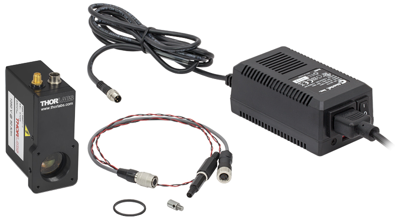
こちらのPMTモジュールは制御電圧用のYケーブルと電源(6ピンヒロセ-2.5 mmモノジャックならびに3ピンLumberg電源コネクタ)が付属します。ケーブルの写真は「発送リスト」のタブをご覧ください。
PMTモジュールのコネクタ
電源コネクタ
6ピンヒロセ
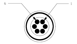
| Pin | Assignment |
|---|---|
| 1 | Power Supply Input (+12 VDC to +15 VDC) |
| 2 | Power Supply Input (-12 VDC to -15 VDC) |
| 3 | 0 V |
| 4 | 0 V |
| 5 | No Connection |
| 6 | 制御電圧 (0 V to +1.25 V) |
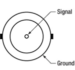
出力信号
SMAメス型
出力電圧:
0~5 V (50 Ω)
0~10 V (High Z)
Yケーブルのコネクタ
電源接続
3ピン Lumberg RKMC-3
| Pin | Assignment |
|---|---|
| 1 | Power Supply Input (+12 VDC to +15 VDC) |
| 2 | Ground |
| 3 | Power Supply Input (-12 VDC to -15 VDC) |
制御電圧
2.5 mmモノプラグ

チップ:グラウンド
バレル:0~+1.25 VDC
モジュールPMT1001/M、PMT1002、PMT2101/M、PMT2102
こちらのPMTモジュールにはSMA-SMBケーブルとMini USB-USB Aケーブルが付属します。これらのケーブルの写真は「発送リスト」タブに掲載されています。
電源コネクタ
USB Mini
入力電圧:
+0.50 V~+1.10 V (PMT1001/M&PMT1002)
+0.50 V~+0.80 V
(PMT2101/M&PMT2102の推奨範囲)
出力信号
SMAメス型
出力電圧:
±1.5 V (50 Ω)
モジュールPMTSS、PMTSS2、PMTSS2-SCM
こちらのPMTモジュールには色ワイヤーリード付きのオス型M8 x 1コネクタが付属します。コネクタの写真は「発送リスト」のタブをご覧ください。
電源コネクタ
M8 x 1メス型
| Pin | Assignment | Wire Colora |
|---|---|---|
| 1 | Power Supply Input (+15 VDC) | Brown |
| 2 | 制御電圧 (Recommended: +0.25 V to +1.00 V; Maxb: +0.25 V to +1.20 V) | White |
| 3 | No Connection | Blue |
| 4 | Power Supply Return (Ground) | Black |
出力信号
BNCメス型
出力電流:10 µA(最大値)
Click to Enlarge
PMM01およびPMM02
PMM01、PMM02
型番PMM01およびPMM02の内容
- PMTモジュール
- 固定リングSM1RR
- M4 - #8-32ネジアダプタAS4M8E
- 制御電圧用Yケーブルと電源(6ピンヒロセ-2.5 mmモノジャックならびに3ピンLumberg電源コネクタ)
- 2.5 mmモノプラグ
- ±12 V電源&電源ケーブル(日本国内用)
Click to Enlarge
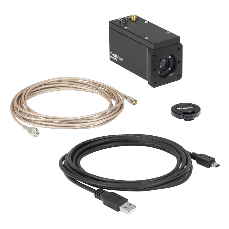
PMT1001(/M)
PMT1001(/M)
型番PMT1001/Mの内容
- PMTモジュール
- USB 2.0ケーブル(A - Mini)
- SMA - SMBケーブル
- SM1用エンドキャップ
Click to Enlarge
PMT1002
PMT1002
型番PMT1002の内容
- PMTモジュール
- USB 2.0ケーブル (A - Mini)
- SMA - SMBケーブル
- C-Mount用レンズキャップ(代替品 型番CMCP2)

Click to Enlarge
PMTSS
PMTSS
型番PMTSSの内容
- PMTモジュール
- カラーリード線付きオス型M8 x 1コネクタ
- M8 x 1延長コード
- Cマウント用キャップ(代替品 型番CMCP2)

Click to Enlarge
PMT2101(/M)
PMT2101(/M)
型番PMT2101(/M)の内容
- PMTモジュール
- USB 2.0ケーブル (A - Mini)
- SMA - SMBケーブル
- SM1用エンドキャップ

Click to Enlarge
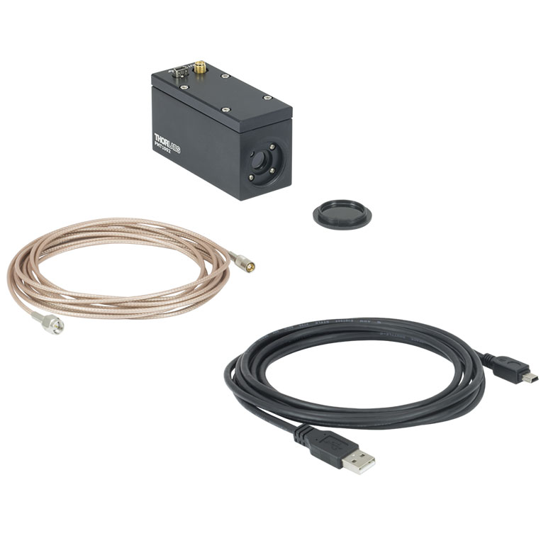
PMT2102
PMT2102
型番PMT2102の内容
- PMTモジュール
- USB 2.0ケーブル (A to Mini)
- SMA - SMBケーブル
- C-Mount用レンズキャップ(代替品 型番CMCP2)
Click to Enlarge
PMTSS2
PMTSS2
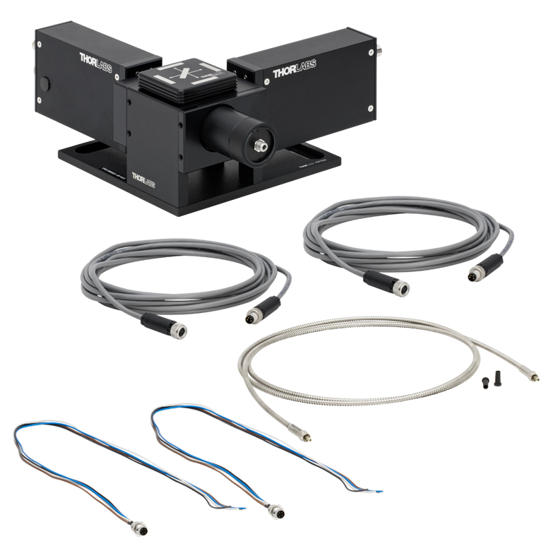
型番PMTSS2の内容
- 取外し可能なPMTモジュール(2台)
- フィルターキューブトップDFM1T1
- SMA905付きファイバーコリメーターアセンブリと、アドオン式モジュールPMTSS2-SCMとの
接続用のオス型アリ溝の付いた筐体 - カラーリード線付きオス型M8 x 1コネクタ(2個)
- M8 x 1延長コード 2本
- コア径Ø910 µm、NA0.22、SMA905コネクタ付きファイバーパッチケーブル、250~1200 nm用
Click to Enlarge
PMTSS2-SCM
PMTSS2-SCM
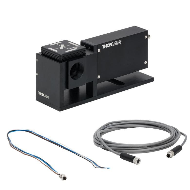
型番PMTSS2-SCMの内容
- 脱着式PMTモジュール
- フィルターキューブトップDFM1T1
- PMTSS2と接続するためのメス型アリ溝と、PMTSS2-SCMを追加するための
オス型アリ溝の付いた筐体 - カラーリード線付きオス型M8 x 1コネクタ
- M8 x 1延長コード
PMT1001/M、PMT1002、PMT2101/M、PMT2102は当社のソフトウェアで制御可能です。 ソフトウェアのダウンロードページには、GUIインターフェイスへのリンクの他、ソフトウェア開発キット(SDK)へのリンクもあり、カスタム仕様のイメージングソフトウェアでPMTを制御することも可能になります。また、PMT用の最新のファームウェアもご用意しています。
ソフトウェア
Version 4.0 (June 7, 2019)
こちらのPMT1001/M、PMT1002、PMT2101/M、PMT2102用のソフトウェアパッケージには、GUIインターフェイス、SDK、および最新のファームウェアのインストールファイルも含まれています。ソフトウェアはWindows®7または10(64ビット)に対応しています。
お客様の用途に合わせた光電子増倍管の選択
はじめに
光電子増倍管(PMT)が最初に 市販化されたのが1940年代初頭ということもあり、PMTは高速反応と高感度が求められる実験に適した検出器とされてきました。今日ではPMTは、分析化学、素粒子物理学、医学的イメージング、工場における工程管理、天文学そして原子・分子物理学など多岐に渡る研究分野で欠かせないものとなっています。このチュートリアルでは、使用用途に適切なPMTを選ぶ上で参考となる基本原理と重要な仕様についてご説明します。
基本原理
光電子増倍管(PMT)は、高感度で高利得のデバイスで、入射光に比例した電流を出力します。PMTは、フォトカソードと呼ばれる光電子放出材料を収納する ガラス製真空管、ダイノードと呼ばれる8から14個の2次放出電極、そしてアノードと呼ばれる電子収集電極から構成されています。エネルギ値が十分に高い光子(エネルギ値がフォトカソード材料の結合エネルギより大きい場合)がフォトカソードに入射すると、吸収されて、光電効果により電子が放出されます。最初のダイノードが、陰極と比べて高い電位で維持されるので(したがって2つの素子の間に電位差が生じます)、放出された電子は加速的にダイノードに 向かって衝突し、2次電子放出が起こります。通常このプロセスにおいては、3~5個の2次電子が放出され、各電子は同様に2つ目のダイノードに向けて加速、衝突し、さらに3~5個の電子が放出されます。このプロセスは、一連のダイノード全てにおいて順番に起こり、電 子が3~5ずつ増えます。通常ではダイノードは、前の電位と比較して100~200 V 高い電位を保持します。ダイノードチェーンの終わりでは、カソードが電子を集めて電流パルスが出力されます。しかしながら、パルスの数量化には、ボルトへの変換が必要となります。これを行う最も簡単な方法は、カソードとグラウンドの間で低い負荷抵抗を接続することです。当社がご提供する2つのPMTでは、カソードから出力されるナノアンペアまたはマイクロアンペアレベルの電流を、それぞれミリボルトまたはボルト単位の電圧にトランスインピーダンス増幅器 (TIA)を用いて変換します。
例えば、下図のようにPMTに8つのダイノードがあって、1つの電子が4つの2次電子を生成すると、全てのダイノードを通過した後の電流の増幅は最終的に48 ≈ 66,000となります。このPMTの例では、各光電子はアノードでQ = 48eの電子なだれを起こします。Cがアノード(接続部を含む)の静電容量である時、それに対応する電圧パルスは V = Q/C = 48e /CTとなります。静電容量が5 pFの時、出力電圧パルスは2.1 mVとなります。
スぺクトル感度
使用目的に合わせてPMTを選択したい場合、フォトカソードの材料が目的の用途に適したものである必要があります。一般的には、長波長のカットオフはフォトカソードで決まります。一方で短波長のカットオフはウィンドウ材料で決まります。PMTは、深紫外域から赤外域までの波長用に製造されていますが、フォトカソードが入射光子を電子に変換する決め手となるので、使用される波長で効率の良く変換されるかが最重要ポイントとなります。フォトカソードには幅広い種類の材料が使用されていますが、材料によって仕事関数は異なり、また使用されるスペクトル範囲も異なります。
量子効率(QE)の仕様値は通常百分率で表記され、入射光子を検出可能な電子に変換するPMTの能力と関連付けられます。例えば、QE値が20%である場合、フォトカソードに衝突する5つの光子のうち1つが光電子を生成することを意味します。光子計数では、QE値の高いPMTを使用することが望ましいと言えます。QEは波長に依存するので、対象となる波長での量子効率が適切なPMTを選ぶことが重要です。特記すべきは、可視光用のフォトカソードのQE値が通常は30%未満であることです。
PMTのQE値は、スペクトル感度プロット( 「グラフ」タブ)を参照しながら下記の数式を使えば計算できます:
![]()
放射感度SがA/W単位で、波長λがnm単位である時。
形状
PMTは主に2つの異なる形状でご提供しています。ヘッドオン型(フォトカソードが真空管のいずれかの先端に有る)とサイドオン型(フォトカソード素子が真空管 の側面に有る)があります。ヘッドオン型のPMTには半透明のフォトカソードがあり、集光面が広いのが特徴で、空間均一性に優れており、青と緑のスペクトル領域で優れた性能を発揮します。分光法など広いスペクトル領域における用途では、ヘッドオン型配列が推奨されます。反対にサイドオン型PMTには、不透明なフォトカソードがあり、UVおよび赤外域での使用に向きます。この構成はヘッドオン型より低コストで、分光計やシンチレーション計数等の効率的な光学カップリングや高いQE値が要求される用途で広く使われています。
8~14個からなるダイノード配列として、線形または円形配列が採用されています。線形ダイノードアレイ(上の図の配列)は、反応が速く、時間分解能が良く、パルスの直線性が非常に優れているので、一般的に採用されています。円形タイプのアレイは、全てのサイド オン型のPMTと一部のヘッドオン型PMTで採用されています。これはコンパクトで高速反応の構成です。
利得
PMTの特長は、フォトカソードが生成した非常に弱い信号を、実質的にノイズなしで、読み出し回路ノイズを超える検出可能なレベルまで増幅できる点です。 PMTでは、ダイノードにより利得が得られます。利得は印加電圧に高く依存しています。PMTは、メーカーの推奨値をはるかに超えた電圧で動作することが 可能で、仕様の数値の10から100倍の利得を生み出すことがあります。通常アノード電流が定格値より十分に下回って抑制されていれば、このことがPMT に致命的な影響を与えることはありません。当社がご提供する2つのPMTでは、ヘッドオン型フォトカソード形状と円形のダイノードチェーンが両立されています。
暗電流
フォトカソードで生成される全ての信号が、チューブへの入射光で生成された電流に 起因することが理想ですが、現実にはPMTは光の有無に関係なく電流を生成します。光がない状態で発生する信号は暗電流と呼ばれ、これがPMTの信号とノ イズの比率を悪化させます。暗電流は、主にフォトカソードからの電子放出と最初の数個のダイノードに大きく左右されますが、非常に微小ながら宇宙線や放射 性崩壊の影響も受けます。一般的には、赤色のスペクトル用に設計されたチューブでは、赤色感知のフォトカソードの結合エネルギが低いので、他の場合より多くの暗電流が検知されます。暗電流の主なる原因がフォトカソードからの熱電子放出と予想される場合は、暗電流計数率は下記の数式で求められます:
![]()
熱電子放出は温度とフォトカソードの仕事関数に大きく依存するので、PMTを冷却すれば暗電流計数を大幅に削減できます。当社の共焦点ならびにBergamo顕微鏡システムに付属する熱電冷却器付のPMTは、20oC から0oC に冷却すると、暗電流は最大で1/10に減らすことができます。熱電冷却器を使う場合は、ウィンドウ部分で結露が起こらないように留意する必要があります。結露が生じると、水分によりフォトカソードへの光の入射量が減少します。さらに過剰な冷却も逆効果になりえるので避けなければなりません。逆効果の例としては、カソードの薄膜の抵抗値が温度に反比例することで起こるカソード全体の電圧降下や信号減少があります。
立ち上がり時間
高い時間分解能が要求される実験では、短い立ち上がり時間は不可欠です。PMTの時間反応特性値として最も一般的に取り上げられるのは、アノードパルス立ち 上がり時間です。アノードパルス立ち上がり時間とは、フォトカソードが十分に照射されたとき、PMTの出力がそのピーク振幅の10%から90%に上昇する までにかかる時間と定義されます。当社のPMTシリーズ製品の立ち上がり時間は、「仕様」タブでご覧いただけます。
最終的には、パルス立ち上がり時間は、異なる電子の移動時間の広がりで決定されます。このような時間のばらつきがあるのにはいくつかの理由があります。まず、2次電子がダイノード材料の異なる深度から放出されるので2次電子の初速にばらつきがあることが第1の理由です。一部の電子がダイノードからの放出段階で初期エネルギを全く持たない状態であるのに対し、非ゼロの初期エネルギを保持する電子もあります。つまり後者の方が前者と比較 して短時間で次のダイノードに到達するわけです。また、電子が最初に放出された時の速度のバラツキに加えて、通過時間の広がりには、電子軌道の長さのバラツキの影響もあります。このような原因で、アノー ドパルスは、電圧が上昇するにつれてV-1/2数値で減少します。
他の検討事項
検討すべき重要な事項は他にもあります。まず、PMTと共に使用する電子部品の選択には注意が必要です。カソードからアノードに向けて付加される高電圧の変化は小さなものであっても、出力結果を大幅に変えることがあります。次に、実験環境がPMTの性能に影響を与える可能性も勘案してください。振動はもちろん、温度や湿度の変化も全てチューブの性能を損ないます。チューブの筐体も大事です。筐体はチューブを外部光や無関係な光から遮断するだけではなく、外部の磁場の影響も抑制します。磁界の影響は数ガウスであっても、利得を格段に減少させますが、このような悪影響は高透磁性の材料で作られた磁気シールドを用いれば最小限に抑えられます。
| Posted Comments: | |
Frank DeLucia
(posted 2023-07-18 10:27:51.62) I have purhcased several of these PMT1001s and am quite happy with there ease of use and performance. IS there any chance you have a 32 bit version of the software that operates them? I have a certain application that is run by a computer with a 32 bit operating system. Thank you cdolbashian
(posted 2023-07-25 09:17:02.0) Thank you for reaching out to us with this feedback! At this time, we are unable to provide a 32-bit software for these PMTs. I apologize for the inconvenience. Zhang Rui
(posted 2023-06-16 17:48:21.82) We are researchers from Peking University. We bought the PMT of PMM02-1 before. Would you like to know whether there is a supporting data acquisition card or the recommended acquisition card? Thanks! cdolbashian
(posted 2023-06-21 11:09:04.0) Thank you for reaching out to us with this inquiry. Looking at the specs tab above, these PMTs output an analog voltage signal up to +-10V with speeds up to 25kHz. You would simply need to find a data acquisition card which can support these speeds and voltage inputs. I have contacted you directly to discuss this further. Oscar Gomez Calderon
(posted 2023-04-26 07:06:47.91) Dear Sir, we are interested in the PMT2100 Series. We have a computer with windows 7 32bit. Is it possible to use the control software in a 32 bit computer or is there any other way to control the PMT?
Thank you very much ksosnowski
(posted 2023-05-01 09:33:18.0) Thanks for reaching out to Thorlabs. Unfortunately the PMT2100 software package was never built for 32 bit environments, and there is not a straightforward way to enable this functionality for our application. We apologize for this inconvenience. Shouwen Ma
(posted 2023-02-23 19:24:29.98) I have a question about setting the output offset rather than a feedback.
I am a new user of PMT2101/M for a Galvo-resonant scanner. It is not clear to me to the instruction 6.5.3. - Setting the PMT2100 Offset. (use the table below to configure all the PMT 2100s.) should I close all the light and capture images with output offset 0v, then increase the gain until average pixel values is 50-100. Do I eventually take the value of the gain as the value of output Offset? Or should I set an value of output offset, then adjust the gain until average pixel values is 50-100? and what value should I give?
Or should I leave the output offset on throlabs control panel always to be 0 and use the software such as scanImage to measure the output offset as indicated here https://docs.scanimage.org/Configuration/PMT/index.html.
I am looking forward to your information.
Shouwen ksosnowski
(posted 2023-03-24 03:04:01.0) Hello Shouwen, thanks for reaching out to Thorlabs. For questions like this you can contact techsupport@thorlabs.com directly. The output from a PMT is negative and can be offset using our PMT Software control window. The maximum voltage output in conjunction with the offset is +/- 1.5V. Setting the offset close to negative 1.5V risks clipping data. To avoid saturation, the output signal should not exceed the maximum output voltage. This will adjust the actual voltages coming out of the PMT's transimpedance amplifier (TIA). You can use other software to further adjust the offset from the data you receive. Generally using a more positive offset will increase the dynamic range of the TIA due to the negative PMT output. I have reached out directly to discuss your application further. user
(posted 2023-01-06 03:04:47.1) We have bought a PMM01 from your company for taking CH chemiluminescence data from combustion experiments. I am unsure on how to set up the PMT,
a) setting up the power supply, the first time I connected the main power supply to the power supply (12V) adapter you had provided the adapter burnt. We bought the PMT to use in India, does it have anything to do with the normal power supply ratings of 230V in India?
b) I would also like to know how to use the Y cable, one line of the Y cable is connected to the power supply adapter, the other I'm not sure how to use. Do I have to connect it to a variable power source? If so I have a DAQ wherein I can use the LabVIEW software to supply the necessary variable voltages to the PMT, is this right?
c) I'm not sure how to use the variable power source, please enlighten me on how to use or what settings I have to use approximately to get data of CH Chemiluminescence which emits light at 430nm. ksosnowski
(posted 2023-01-18 03:37:35.0) Thanks for reaching out to Thorlabs. The LDS12B power supply that comes with the PMM01 has a selector to switch between 115V and 230V regions. By default this is set to 115V so will need to be switched here. The Y cable is used to apply the HV Control Voltage, and can be connected to a voltage source of user choice. We do not sell a specific supply for this as there are many benchtop variable voltage sources available from other providers. If your DAQ can output voltages then it could be used for this. A source with low voltage ripple is recommended, as any noise on this control voltage will directly effect the high voltage across the PMT tube, and hence the tube gain. I have reached out directly to discuss your application further. Shulang Lin
(posted 2022-12-22 19:18:42.8) we have purchase several PMT2101 to detect TPF signal, while we found that the output voltage is always negative and only 70-100mV. May I know whether there is any setting could let the output be same as +-1.5V as the description? ksosnowski
(posted 2022-12-28 05:09:02.0) Thanks for reaching out to Thorlabs. The DC offset, Bandwidth, and Control Voltage can all be set through our PMT Software. The PMT2101 manual covers the software install on pages 9-23. Page 26 shows how to change the DC offset. The Control Voltage will effect the PMT Gain, which will scale the output voltage swing resulting from your signal amplitude above background level. It is recommended to keep the output voltage below the +1.5V Max as this will saturate the amplifier. Page 7 also has the equation for output voltage based on optical power and gain settings. I have reached out directly to discuss your application further. Sean Su
(posted 2022-08-26 16:05:07.477) I tried to use the LabView sample file named "PMT2100Test.vi" in the SDK to Link the PMT, but the Find Devices function keeps responding with Device Counter = 0. I confirm that the Driver is installed and your application works, but it still doesn't work on my LabView program. Is there any solution? cdolbashian
(posted 2022-09-07 03:58:30.0) Thank you for reaching out to us. The most important thing when using our LabView samples is to keep all of the dependent files within the same relative path to the Vi. I have contacted you directly to troubleshoot your exact issue. minhui liang
(posted 2022-07-07 01:32:38.183) Hi, I wonder how to calculate the relative fluorescence unit by this PMT? RFU = U/(G^a), where U is the output voltage and G is the gain. But the exponent a should be provided by the manufacturer. I wonder where can I find this value. Thank you! cdolbashian
(posted 2022-07-19 11:38:16.0) Thank you for reaching out to us Minhui. After reading the reference to which you found this equation, it seems like the author was referring to G with a unit of Volts, which seems to imply a control voltage and thus the exponent seems to be the exponential relationship between the control voltage and the gain value, as shown similarly our gain curves. It is unclear though if this is exactly the interpretation, as the author of the referenced paper was very brief. Xindong Song
(posted 2022-05-17 17:23:46.607) Question about the GaAsP PMT: PMT2201(2). The "Specs" tab shows the anode current is 500 µA (Max). This is far beyond the value of Hamamatsu H10771-40 or any of the H7422 series, which typically has an anode output current of 2 µA (Max), with the exceptions of the very latest models (H16200(1)P-40) that have a 40 µA (Max), Is this 500 µA (Max) true? or maybe due to different ways of defining the anode current? or a typo? I assume this PMT is based on the Hamamatsu H10771. Thanks. cdolbashian
(posted 2022-05-27 12:30:45.0) Thank you for reaching out to us with this inquiry. We do indeed use the H10771-40, as stated in our manual. We use a modified version that trips at 50 µA in the PMT2100 as an average current over ~100us. Since the response time of a 2P laser happens on the order of only 10 ns , the average current still falls within the specified amount. The trip only comes into play for sustained high photon flux usage. Impulses can be significantly higher. 500 µA before the amplifier is allowed (anode current). But it must be of short duration, i.e. a few 2P laser cycles while scanning past a bright cell body. I have reached out with you to discuss this further in context of your application. user
(posted 2021-11-30 22:12:35.27) We have a 32-bit system and want to control this PMT with our own developed program. Is it possible? I see the disk has an installation of NI-VISA and Keysight IO, does it mean the control is based on VISA? Can you provide me the command reference to control the PMT with our own program? Thanks!
Cheers
Tao cdolbashian
(posted 2021-12-23 02:03:44.0) Thank you for reaching out to us Tao! Serial commands are included in the manual for the device. Regarding an SDK, I have contacted you directly with some example code and documentation for use with your PMT. Byeongjun Seok
(posted 2021-10-02 21:25:47.91) We are using PMM01 together with power supply and connectors. After several years, the 6-pin Hirose to 3-pin Lumberg connector is broken, so I was wondering you carry this part separately. Thanks. YLohia
(posted 2021-10-15 11:48:23.0) Thank you for contacting Thorlabs. Custom and component items can be requested by emailing techsales@thorlabs.com. We will reach out directly. Will Jou
(posted 2020-11-10 10:28:04.86) Dear Sir, I'd like to purchase a PMT. After comparing different products, however, it seems that APD performs better than PMT. For example, the APD410A2 typical max
responsivity is 25 A/W at 600nm and M=50 while PMT2101 radiant sensitivity is only 176 mA/W at 550nm. What's more, the APD410A2 max conversion gain is 12.5 x 10^6 V/W while PMT2101 gain is only 1 x 10^6 V/W. I prefer PMT than APD, but can you tell me PMT advantages compared to APD, after all PMT's price is more than APD. Looking forward to your reply and thank you in advance. asundararaj
(posted 2020-12-29 03:15:23.0) Thank you for contacting Thorlabs. The choice of the PMT vs. APD comes down to the specifications and your preference. A lot of imaging applications, for example, prefer a PMT over an APD. In addition to the specifications you compared, the noise floor in the PMT is going to be much less. The PMT2101 has a higher bandwidth - 80 MHz (at low signal) vs 10 MHz for the APD410A2. The active area for the PMT is larger - 5 mm vs. 0.5 mm for the APD. I have contacted you directly to discuss your needs. Mark Hui
(posted 2020-02-27 05:02:46.033) We are applying PMT1001 for our fluorescence measurement. According to PMT1000 Series User Guide, the PMT Gain is linearly proportional to Control Voltage in Figure 3. How is Control Voltage related with GAIN in Program PMT2100? Also, what is the PMT Gain in Figure 3? What is the relationship between the PMT Gain and GAIN in the program?
Thanks,
Mark llamb
(posted 2020-02-28 10:45:17.0) Hello Mark, thank you for contacting Thorlabs. For future reference, you may email us at techsupport@thorlabs.com directly for application support and spec questions. You can find the same Gain vs. Control Voltage plot for the PMT2100 series in their respective manuals, as well as under the "Graphs" tab on this webpage. In the software, the user can set the Control Voltage (see Figure 38 in the PMT2101's manual) which corresponds to the Gain as per the same plots mentioned above. Mark Hui
(posted 2020-02-27 02:28:14.913) Dear Sir,
We are applying Labview 2014(32bits) to control PMT1001. We attempt to open the Labview programs in SDK. But we cannot open the Labview programs, because the Labview programs cannot link with the dynamic library. Could you please help?
Thanks,
Mark llamb
(posted 2020-02-28 10:36:07.0) Hello Mark, our PMT software is only compatible with 64-bit Windows® 7 or 10 systems. I would suggest switching to a 64-bit system if possible, and do apologize for any inconvenience this may cause. Mark Hui
(posted 2019-09-24 19:25:31.61) Dear Sir,
We plan to apply the PMT1001 to measure the periodic modulation of fluorescence signal. So, the PMT 1001 signal is fed into a lock-in amplifier to measure the AC component.
According to the manual (Page 9), the maximum output of PMT1001 is +-1.5V. I tune the DC offset and check the PMT output voltage, when the PMT is kept in dark.
DC Offset = 1V, Output Voltage =2.21V
DC Offset = 0V, Output Voltage =0.014V
DC Offset = -1V, Output Voltage =-2.19V
Which DC Offset should we apply to PMT1001 for our experiment? How can we set the DC offset for PMT1001?
Thanks,
Mark nbayconich
(posted 2019-10-25 03:21:22.0) Thank you for contacting Thorlabs. We suggest to keep the maximum output voltage between -1.5 & +1.5volts otherwise the transimpedance amplifier will saturate.
If the voltage is too high please adjust the DC offset until the output voltage is at a suitable level or attenuate your input signal using a neutral density filter.
Note that the output voltage of this PMT is a negative voltage. The offset voltage setting will depend entirely on your application requirement, in the case where you may be reading the output of your PMT to a DAQ instrument that can only accept a positive voltage range then you may need to apply a higher + DC offset to the PMT in order to read the signal on your DAQ card. trose
(posted 2018-10-06 10:15:32.54) We are having a lot of issues with PMT tripping of our PMT2100. As far as I understand this is due to the adjustable secondary amp trip circuit - not the 50uA primary trip threshold of the PMT.
Would it be possible that you expose the VOLTage[:DC]:PROTection commands (Appendix A) in a future version of the PMT control software? It would be extremely helpful for us to fine-tune trip levels, switch off the protection etc.
I am aware that this is a safety feature that is potentially dangerous - I also know that we can set these values ourselves using the Keysight IO libraries. It would be more convenient to have this in your software, though.
Also: What is the Voltage Level you currently use for the PMT2100 trip circuit? As far as I can see there is no way to read this out currently. Across which range would you suggest to change these values?
Tobias Rose llamb
(posted 2018-10-23 08:29:44.0) Hello Tobias, thank you for your feedback. Generally, the trip circuit prevents the PMT from overexposure, so we do not recommend removing it, nor is it removable from the PMT2100 series specifically because of their compact size.
For the PMT2100, we factory-set the secondary trip circuit to the max level and have commented out the code on the firmware that allows adjustment, so these are not adjustable nor able to be increased. This secondary circuit could in principle allow you to adjust the trip level below the primary 50 uA trip level, but this primary trip level is actually the limiting factor for the PMT. Our secondary amplifier circuit does not limit the trip level.
We could potentially quote these same PMTs without the trip circuit as custom products, though they would need to be new purchases. I will reach out to you directly to discuss further. htu
(posted 2018-10-05 11:20:56.813) PMT2101 is similar to Hamamatsu H7422-40, with an notable exception that the cooling fan is absent, so that the PMT is more compact. My question is: has Thorlabs done comprehensive test to justify that this cooling fan is not needed (even for long-term operation)? YLohia
(posted 2018-10-17 12:30:38.0) Hello, thank you for contacting Thorlabs. The PMT2101 is actually equivalent to Hamamatsu H10770PA-40, which does not have active cooling either. The requirement of the cooling fan/TEC depends on your specific application and is not a universal necessity. For applications that do not require superior long-term stability and extremely high sensitivity, the PMT2101 is probably sufficient. jos.castelein
(posted 2018-05-01 15:55:33.387) Can you please provide me help with the installation of the PMT1001 drivers for Labview.
Regards, Jos Castelein YLohia
(posted 2018-05-01 12:07:02.0) Hello Jos, I will reach out to you directly to troubleshoot your issues. kuw4214
(posted 2017-08-07 20:24:11.97) Dear Sir/Madam
This is Ui-Whan,Kim in South Korea
I Bought five set of PMTSS and TIA60 for measurement of OH signal.
But today I figure out that I dont have proper power.
Please let me know the proper power model number for each products that I bought
.
Then I will buy immediately for my experiment.
Please contact by an email.
Thank you very much. tfrisch
(posted 2017-09-05 04:29:59.0) Hello, thank you for contacting Thorlabs. PMTSS requires a power supply with 15VDC which limits the supply current to no more than 7mA. I will reach out to you directly since we do not offer such a power supply in our catalog at this time. pwyen
(posted 2016-12-08 10:47:44.503) Hi, this is PW from Taiwan.
I can't fine the figure of the control gain voltage with the PMM01 control gain. Could you kindly send me that figure? Thank you. tfrisch
(posted 2016-12-15 01:22:31.0) Hello, thank you for contacting Thorlabs. Please reference page 5 of the manual here:
https://www.thorlabs.com/drawings/1de4aa08f64cd423-1D709DCD-5056-0103-792BFB6CE1C63899/PMM01-Manual.pdf lleclair
(posted 2016-08-05 06:35:37.237) It would be very useful to me if I could do single photon counting/timing. But with a rise time of 15 µs that's out of questions. Do you offer one without the amplifier so I can attach my own high speed amp for time-of-flight measurements? What is the rise time straight out of the PMT? devin.pugh-thomas
(posted 2015-09-15 15:31:52.85) Can you provide a recommended variable power supply for use with the PMM02? besembeson
(posted 2015-10-01 11:45:57.0) Response from Bweh at Thorlabs USA: Any basic adjustable power supply will work, 0 - 1.25VDc, <1mA. Many common laboratory variable power supplies will work too. You can also make one, by using, for example another LDS1212 (power supply that is supplied with PM tube), add suitable potentiometer and resistor in series (between +12V and ground) to scale the voltage down to 0-2V and limit current to 1mA. ribou
(posted 2015-04-14 14:42:50.4) I could not found on your description of the pmm01 the time rise of the anode, neither the electron transit time.
I would be grateful if you could send the information to me.
Thanks jlow
(posted 2015-04-16 02:58:43.0) Response from Jeremy at Thorlabs: The response time for the PMM01 and PMM02 PMT are limited by the amplifier used. The rise and fall time is about 15µs, which is orders of magnitude higher than the anode rise time and electron transit time. I will contact you directly to discuss more about this. johanna.tragardh
(posted 2015-02-12 17:19:39.533) What length should the 2.5 mm Mono plug controlling the HV for the PMT PMM01 have?
If it is not a standard length - do you sell this as a spare part?
Thanks. cdaly
(posted 2015-02-24 03:58:54.0) Response from Chris at Thorlabs: The required 2.5mm mono plug will be a standard length, 11.0mm overall if I am not mistaken. A spare male 2.5mm mono connector is included so that a third part power supply can easily be made compatible. iec_cortesm
(posted 2013-05-07 19:42:31.093) one year ago I bought a PMT PMM02, unfortunately my +/-12V power supply doesn't work anymore... I try to use a conventional power supply and plug this in the Hirose-3 conector in the interface conector wire, in this conector there are labeled 3 and 1 two pines, can you tell me which pin is for each voltaje? jlow
(posted 2013-08-02 15:58:00.0) Response from Jeremy at Thorlabs: Pin 1 should be for +12V and pin 3 should be for -12V. The other pin is ground. jlow
(posted 2012-07-31 14:30:00.0) A response from Jeremy at Thorlabs: Most basic adjustable source will work fine. The 100uA mentioned in the manual is just the input current spec for the device. Basically the supply required needs to be able to supply 100uA of current. This is more of a control line than a supply line. This voltage is used to set the level of the tube bias voltage. The reason the supply is specified this way is so that a potentiometer can be used to control this signal line. You want to choose your potentiometer resistances so that the 100uA load current does not significantly affect the voltage setting. The current through the pot. should be 10x or more larger than the 100uA. Below is an example.
Ex. - Use a resistor and potentiometer in series between the +12V PMM001 supply and the ground. The wiper would be connected to the control line. The resistor is used to scale the range of the control pot over 0 – 2V. If we set the resistor to 10kOhms and the pot to 2kOhms (12kOhm total resistance) the current will be 12V/12kOhms or 1mA. This is much larger than the 100uA input current so there should be a minimal effect on the input voltage due to the resistive network.
Other supplies that can be used are lab bench top adjustable power supplies, computer controlled DAQ cards, etc. jb693
(posted 2012-07-26 10:14:24.0) I have recently purchased the PMM02 photon multiplier tube. What power supply would you recommend I purchase for the 0-1.8V tube
control voltage? tcohen
(posted 2012-06-13 12:04:00.0) Response from Tim at Thorlabs: Thank you for your feedback. These may be dark counts, but I would like to see your scope shots to further troubleshoot. I have contacted you for more information and to continue this conversation. wpar022
(posted 2012-06-13 01:33:56.0) Hi there,
We have been using a PMM01 and notice with on all power supplies we use with it there is a strong pulse signal at ~200Hz. Increasing PMT gain merely inverts signal around the background level. Increasing gain/optical input power results in pulse signal changing to a semi-sawtooth signal. Observed signal is independant of input signal - input pulses will not result in a corresponding output pulse. Mean signal level is ~10 mV for 50 Ohm termination, and 1-2 V for high impedance. We suspect that our power supplies (all TLabs supplied, with other equiptment, running on 230V) may be damaging the PMT, but are unable to rule out other laboratory sources. Gain control voltage does not exceed 1.4 V. Any insight you may be able to provide would be greatly appreciated! bdada
(posted 2012-01-19 16:05:00.0) Response from Buki at Thorlabs:
Thank you for your feedback and we are sorry it took a while for you to get the PMT working. We will look into improving the instructions in our manual. We did test the PMT and found it to respond to ambient light. When we shone a high power LED against the pinhole in the black tape, the PMT responsed. We have contacted you to discuss this matter further.Please contact TechSupport@thorlabs.com if you have any questions. ji-yi
(posted 2012-01-19 09:59:41.0) Dear Thorlabs, we would like to make a comment on the product (pmm02) and the manual. As in my last post, we had problems on making the PMT work. It turned out the polarity of the gain control voltage should be reversed and now it is working fine. We strongly recommend the manual description and the usage tutorial to be revised. What is very confusing is that in the manual it states that the control voltage is a positive value 0-1.8v. And the cable inputting the control voltage is colored red and black. According to conventional usage of the cable color without specific notation, the black is ground and the red is positive. So what we have tried is always put a positive voltage through the red cable, which should have been the other way around to make it work. We spent a great deal of time on figuring out the problem and I am sure we will not be the last to be confused. Please be more specific on the manual description or on the website especially on how to correctly connect the gain control voltage and I strongly recommend to switch the color of the cable for gain control voltage. Thank you! ji-yi
(posted 2012-01-17 10:31:44.0) Dear Thorlabs, we recently purchased PMM02 and have difficulty to make it work. We used a DC power supply for the 0-1.8V gain control and a oscilloscope to monitor the voltage output(connected with a coaxes cable). The PMT inlet was sealed with a black tape with a tiny pinhole on it. We were not able to see any voltage change when we swept a flash light over the pinhole. When we increased the gain voltage to 0.6v, there is a constant DC voltage increment. But still no response to the light stimuli. Please advise how to trouble shoot. This is actually the second PMT we tested. The same problem persists. Thank you! bdada
(posted 2011-12-26 09:30:00.0) Response from Buki at Thorlabs:
The +/-12VDC power supply is included in the PMM02 photomultiplier module. If you want to purchase extra power supplies, the part number is LDS1212-1 and they can be purchased by calling or emailing our Sales Office at 973 300 3000 or sales@thorlabs.com. We do not sell the variable power supply, but they are available in electronics stores.
Please contact TechSupport@thorlabs.com if you have any questions. lobanov
(posted 2011-12-23 10:14:58.0) Please send a quote and delivery conditions for
1) power supply +-12V for photomultiplier module PMM02
2)Variable 0-18 VDC power supply for photomultiplier module PMM02 jjurado
(posted 2011-06-23 10:55:00.0) Response from Javier at Thorlabs to jsmarkson: Thank you very much for contacting us. We will contact you directly to troubleshoot your application. jsmarkson
(posted 2011-06-17 02:15:02.0) We have purchased two PMM01 modules recently and have experienced sudden, dramatic loss of sensitivity after a few months of use. We use the modules to detect bioluminescence emitted from cells passing through a transparent glass tube. The system is very well insulated from outside light, and we adjust the initial gain (~1000V) so that readings never max out(usually they are in the 0V to 4 V range). However, after several months use, the signal suddenly drops > 100-fold, and increasing the gain to 1500V improves the signal only a few fold at best.
I have heard that PMTs should have lifetimes on the scale of many years even under harsh conditions, but we are experiencing a lifetime of at most a few months in mild conditions (a warm room at 30C @ 40% relative humidity; system is powered on continuously for 1 week and then left off for 1-4 weeks). We once took apart the module and tried replacing the PMT tube itself with a similar one from a third-party supplier. This improved sensitivity for a very short while (weeks?) before we again experienced a 100-fold drop in signal.
Do you know what could be causing this reliability problem and how to fix it? The reliability problem has ruined several experiments already, and we are considering switching to the much more expensive modules from Hamamatsu. We would strongly prefer to stick with ThorLabs if you can help us trace the problem and fix it. jjurado
(posted 2011-02-14 18:03:00.0) Response from Javier at Thorlabs to last poster: Thank you very much for submitting your inquiry. The output from our photomultiplier tubes does not require the use of specialized software for data collection and analysis. You could use a data acquisition card and a program such as LabVIEW in order to analyze the output. Please contact us at techsupport@thorlabs.com if you have any further questions. user
(posted 2011-02-14 14:13:39.0) Do you have any recommendations for software to analyze the PMTs output? Thanks. apalmentieri
(posted 2010-03-03 08:36:28.0) A response from Adam at Thorlabs to mbvincent: There are tubes available that cover the wavelengths that you are interested in. We could offer these as custom options. We do not normally offer complete modules for these tubes for a couple of reasons. Please note there are problems associated with operation of a complete system in the vacuum UV range. Either the complete detector has to be in the vacuum system or the input window of the detector has to form part of the vacuum containment system. These modules are not designed for use under vacuum are likely to outgas and breakdown. The reason outgassing and breakdown may occur is due to the electronics used. UV tubes can be operated in pulse counting mode including photon counting. The electronics required would be an amplifier discriminator and a simple timer counter. apalmentieri
(posted 2010-02-19 15:39:10.0) A response from Adam at Thorlabs to Melsscal: Currently, we only offer a PMT with a 15us rise time. We may be able to offer this version as a custom option, but we would like to get more information about your application. There may be other devices that would also work like our avalanche photo detectors, APD110A. melsscal
(posted 2010-02-19 03:33:42.0) We are looking for a rise time of at least 50ns whereas the PMM01/PMM02 offers only 15 microseconds.Can we get a custom made part with 50ns rise time ? mbvincent
(posted 2009-12-14 13:18:47.0) Dear Thor Labs,
Do you offer a PMT module that covers 115-320 nm (wider range welcome) with a minimum 13 mm diameter active area? What associated electronics are required to operate the PMT in pulse counting mode?
The application is FUV calibration of mirrors and microchannel plate detectors. The PMT will be located within a vacuum chamber (<10-6 Torr).
Regards,
-Mark B. Vincent
Staff Research Associate IV
Dept. of Applied Science
3001 Engineering III
University of California
One Shields Ave
Davis, CA. 95616-8254
Phone: (530) 752-3747
E-mail: mbvincent@ucdavis.edu klee
(posted 2009-12-08 17:50:36.0) A response from Ken at Thorlabs to moweirong: The max current is very small (<1mA), so the power supply does not need much current capability. I would recommend using a linear supply. Almost any bench top supply that is adjustable from 0 to at least 1.8V will work. Something like this will work just fine: http://www.powersupplydepot.com/productview.asp?product=14600+PS moweirong
(posted 2009-12-08 00:20:32.0) Could you please advise what requirements for the user-provided 1.8V control voltage? how much is the max input current, the ripple noise, and the stability? any recommendations of this control voltage unit? thanks klee
(posted 2009-12-07 18:20:55.0) A response from Ken at Thorlabs to moweirong: A 12VDC power supply is included with the PMM02. moweirong
(posted 2009-12-07 17:47:09.0) Same question as melsscal.
Does Thorlab provide power supply unit for hirose cable to connect the PMM02? Tyler
(posted 2009-01-26 13:46:00.0) A response from Tyler at Thorlabs to melsscal: The PMT modules are 120 and 230 V compatible. I updated clarified this point in the web presentation. I also changed the specs tab table to have the weight of the power supply and the weight of the PMT head listed separately. The cable needed to connect the power supply to the PMT head is included with the purchase of the PMT. If you have any further questions, please post them and thank you for helping us improve the clarity of the web presentation. melsscal
(posted 2009-01-26 06:34:28.0) The ordering part no. PMM01-EC(230v ) version is not shwon on website .is it available on ordering ?WHAT DOES ITS MEANS BY WEIGHT OF MODULE & TOTAL WEIGHT ?Similarly there is no part no. as PMM02-EC displayed on website.Do u have a pwoer supply /cable for the 6 pin hirose connector ? |
| Standalone PMTs Selection Guidea | |||||||
|---|---|---|---|---|---|---|---|
| Item # | PMM01 | PMM02 | PMTSS | PMT1001(/M) | PMT1002 | PMT2101(/M) | PMT2102 |
| Photo (Click to Enlarge) | 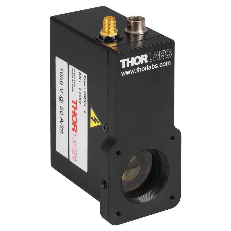 | 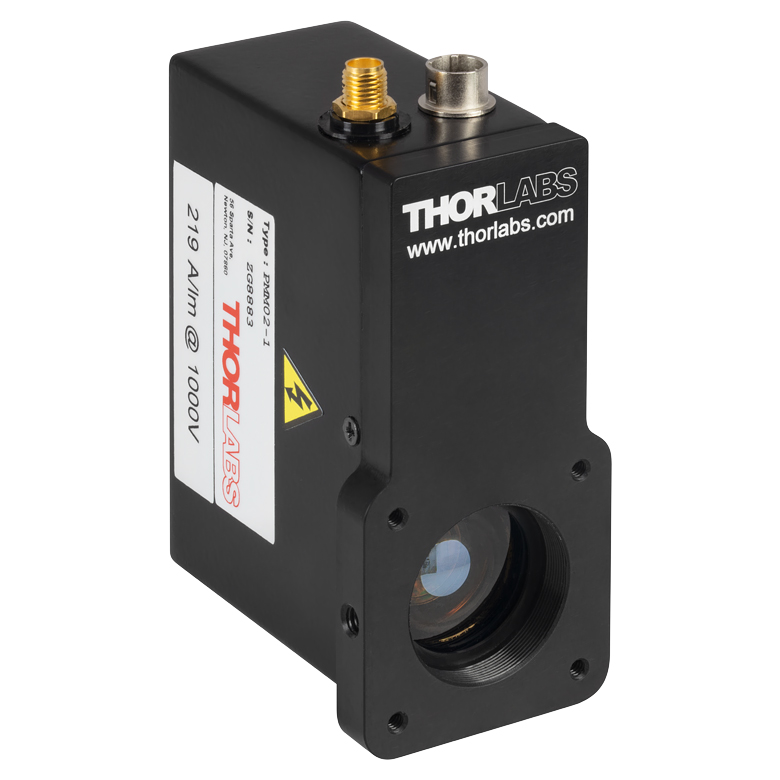 | 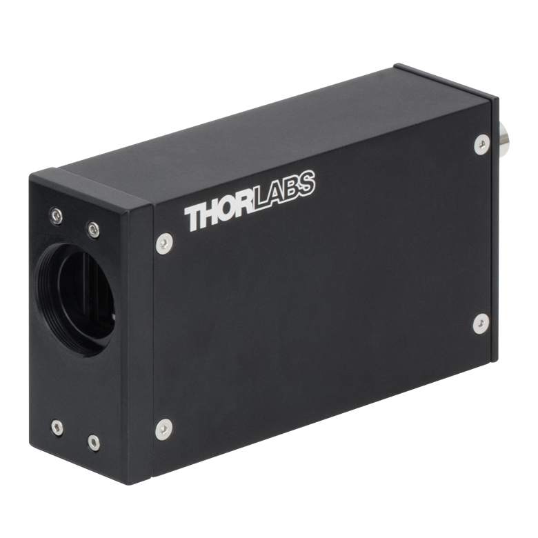 | 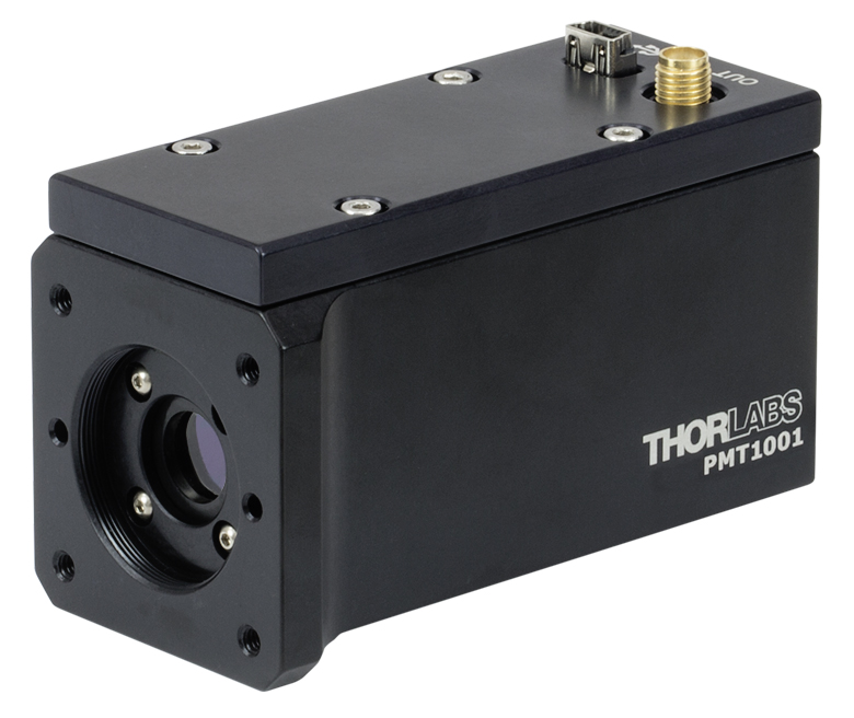 | 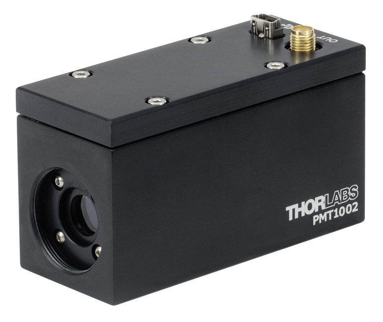 |  | 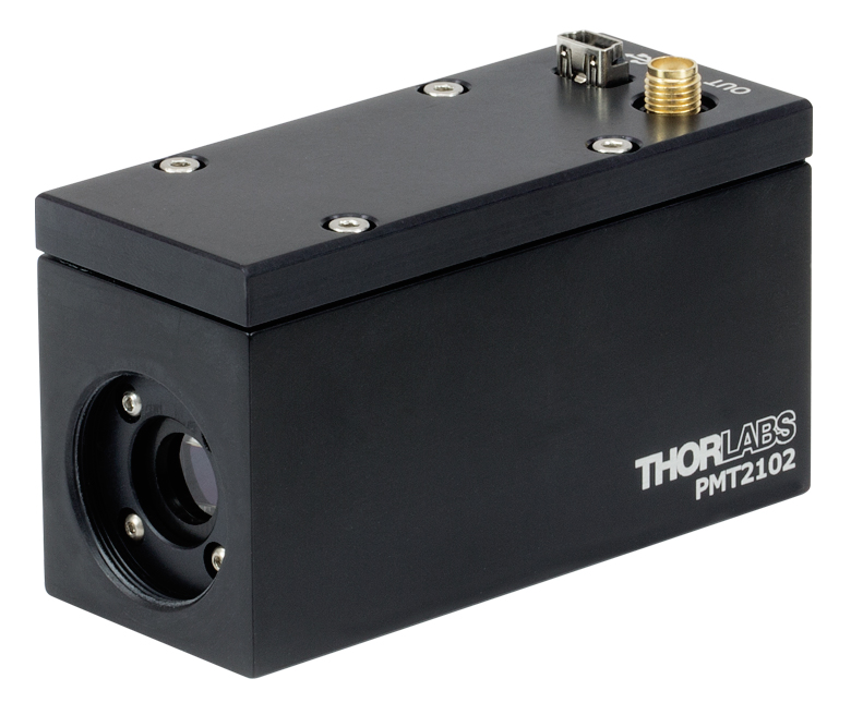 |
| Photocathode Material | Bialkali | Multialkali | Multialkali | Multialkali | GaAsP | ||
| Wavelength Range | 280 - 630 nm | 300 - 800 nm | 185 - 900 nm | 230 - 920 nm | 300 - 720 nm | ||
| Peak Wavelength (λp) | 400 nm | 420 nm | 450 nm | 630 nm | 580 nm | ||
| Radiant Sensitivityb (Typical) | 80 mA/W (at λp) | 51 mA/W (at λp) | 105 mA/W (at λp) | 78 mA/W (at λp) | 176 mA/W (at 550 nm) | ||
| PMT Gain (Max) | 7.1 x 10⁶ | 5.1 x 10⁵ | >1.0 x 10⁷ | >3.0 x 10⁶ | >1.0 x 10⁶ | ||
| Photocathode Active Area | Ø22 mm | Ø21 mm | 3.7 mm x 13.0 mm (H x V) | Ø8 mm | Ø5 mm | ||
| Transimpedance Amplifier | | | Not Included (Compatible with TIA60) | | | | |
| Mechanical Features | Internal SM1 Threads Three 8-32 Taps for Posts (8-32 to M4 Adapter Included) Four 4-40 Taps for 30 mm Cage System | Internal C-Mount Threads | Internal SM1 Threads 1/4"-20 (M6) Tap for Posts Four 4-40 Taps for 30 mm Cage System | Internal C-Mount Threads | Internal SM1 Threads 1/4"-20 (M6) Tap for Posts Four 4-40 Taps for 30 mm Cage System | Internal C-Mount Threads | |
| |||||||
| Multi-Channel PMTs Selection Guidea | |||||||
|---|---|---|---|---|---|---|---|
| Item # | PMTSS2 | PMTSS2-SCM | |||||
| Photo (Click to Enlarge) | 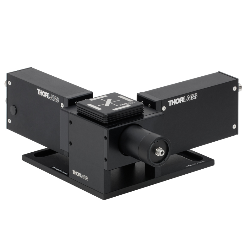 | 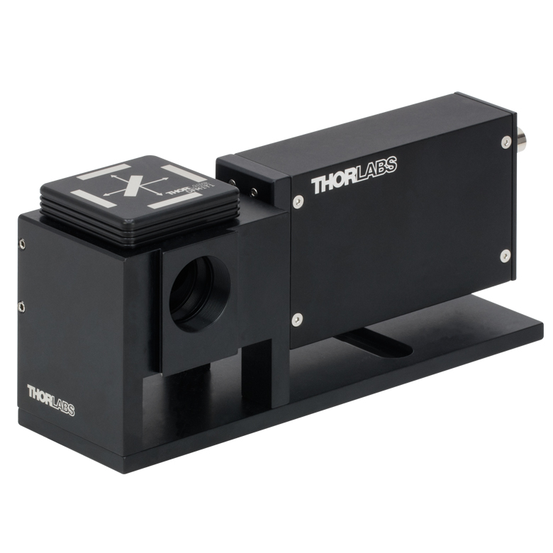 | |||||
| Number of Channels | 2 | 1 | |||||
| Photocathode Material | Multialkali | ||||||
| Wavelength Range | 185 - 900 nm | ||||||
| Peak Wavelength (λp) | 450 nm | ||||||
| Radiant Sensitivity at λpb | 105 mA/W | ||||||
| PMT Gain (Max) | >1.0 × 10⁷ | ||||||
| Photocathode Active Area | 3.7 mm × 13.0 mm (H × V) | ||||||
| Transimpedance Amplifier | Not Included (Compatible with TIA60) | ||||||
| Mechanical Features | SMA905 Fiber Coupler Internal SM1 Threads (by Disconnecting Fiber Coupler) 1/4" (M6) Counterbored Slots for Table Mounting Interlocking Dovetails Optically Align Additional Channels | ||||||
| |||||||

 ズーム
ズーム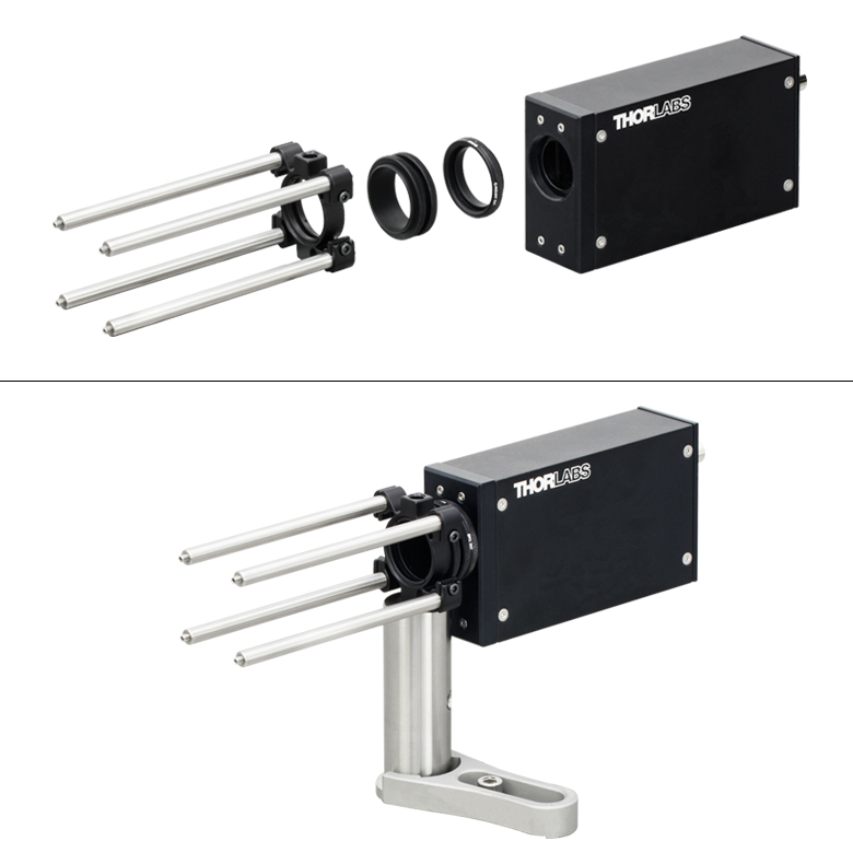
Click to Enlarge
モジュールPMTSSをポストや30 mmケージシステム、あるいはSM1レンズチューブに取り付ける場合、Cマウント-SM1ネジアダプタSM1A9とレンズチューブカプラSM1T2を使用すると、当社の多くの30 mmケージプレートが利用可能になります。

Click to Enlarge
モジュールPMM01およびPMM02には、ポスト取付け用の3つの#8-32タップ穴、30 mmケージシステム用の4つの#4-40タップ穴に加えて、レンズチューブやフィルタ取付け用のSM1内ネジがあります。

- PMM01:280~630 nm用PMT、電圧出力(アンプ内蔵)、SM1ネジ付き、30 mmケージシステムに対応
- PMM02:300~800 nm用PMT、電圧出力(アンプ内蔵)、SM1ネジ付き、30 mmケージシステムに対応
- PMT1001/M:230~920 nm用PMT、電圧出力(アンプ内蔵)、SM1ネジ付き、30 mmケージシステムに対応
- PMT1002:230~920 nm用PMT、電圧出力(アンプ内蔵)、Cマウントネジ付き
- PMTSS:185~900 nm用PMT、電流出力、Cマウントネジ付き
当社では単独型アルカリPMTを4種類のパッケージでご用意しております。パッケージによって出力信号と取付け方法が異なります。「グラフ」のタブでは各PMTの放射感度を比較したプロット図がご覧いただけます。放射感度は量子効率に密接に関係しています。詳しい仕様については上の「仕様」タブをご覧ください。
これらのPMTにはSM1またはCマウントネジが付いており、当社の30 mmケージシステムおよびSM1レンズチューブ用アリ溝アダプタが取り付け可能です。お手持ちの当社の共焦点および多光子システムへの組み込みをご希望の場合は、当社までご相談ください。
PMM01、PMM02
こちらのPMTモジュールの検出部はそれぞれØ22 mmとØ21 mmです。トランスインピーダンスアンプが内蔵されているため、SMAコネクタから電圧信号を直接出力します。PMTのバイアス用制御電圧は2.5 mmモノジャックから供給します。バイアス制御には、+1.8 V(PMM01)または+1.25 V (PMM02)まで供給できる可変電圧電源が必要です。各モジュールには、ご自身で適切な低ノイズ電圧電源に接続できるよう、2.5 mmモノプラグが付属します。
光電陰極はSM1内ネジの奥にあります。SM1内ネジを利用すればPMTをSM1レンズチューブに取り付けられ、不要な光源からの散乱光が光電陰極に入るのを防いだり、Ø25 mm~Ø25.4 mm(Ø1インチ)のNDまたはバンドパスフィルタを取り付けたりすることができます。フィルタを直接取り付けることは入射窓に接触することになりますのでお勧めしません。また、当社の30 mmケージシステム用に4つの#4-40タップ穴も付いています。筐体の3つの側面には、Ø12 mm~Ø12.7 mm(Ø1/2インチ)ならびにØ25 mm~Ø25.4 mm(Ø1インチ)のポストへの取付け用に、#8-32タップ穴が付いています。ミリ規格のセットアップ用にM4 - #8-32ネジアダプタ(型番 AS4M8E)が付属しています。
こちらのPMTモジュールには±12 V電源と国内対応の電源ケーブルが付属します。交換用の電源については下記をご参照ください。
PMT1001/M、PMT1001、PMT1002*
こちらのPMTの光電陰極の検出部はØ8 mmです。トランスインピーダンス増幅器が内蔵されているため、SMAコネクタから電圧信号を直接出力します。PMTの電力供給と制御はUSB 2.0 miniポートを介して行います。ここでは350 mA、4.5~5.5 VDCが供給されます。PMTとPCを接続するUSB 2.0 type A to miniアダプターケーブルが1本付属しています。PMTはPC制御のソフトウェア(「ソフトウェア」タブからダウンロード可能)で制御可能です。ソフトウェアはWindows® 7または10 (64ビット)に対応しています。
こちらのPMTは、2種類のパッケージでご用意しており、幅広い取り付けオプションを実現しています。 PMT1001/MはSM1内ネジ付きで、SM1レンズチューブに接続できます。 また、4つの#4-40タップ穴を使用して30 mmケージシステムに取り付けたり、M6タップ穴を使用して当社のØ25 mm~Ø25.4 mm(Ø1インチ)ポストなどに取り付けたりすることもできます。PMT1002はCマウント内ネジ付きで、Cマウントエクステンションチューブに接続できます。
PMTSS
こちらのPMTモジュールの検出部は3.7 mm × 13.0 mm (H × V)です。BNCコネクタからは電流信号が出力されます。モジュールPMM01やPMM02とは異なりトランスインピーダンスアンプは内蔵されていませんが、当社ではトランスインピーダンスアンプTIA60を別途ご用意しております。PMTにバイアスをかけるための制御電圧は、メス型M8 x 1コネクタから供給します。バイアス制御には+1.20 Vまで供給できる可変電圧電源が必要です(詳細は「グラフ」タブをご覧ください)。各モジュールにはリード線付きのオス型M8 x 1コネクタが付属しているので、ご自身で適切な低ノイズ電圧電源を接続できます。
光電陰極はCマウント内ネジの奥にあります。このCマウント内ネジによりPMTをCマウントエクステンションチューブに接続することができ、それにより不要な光源からの散乱光が光電陰極に入るのを防いだり、Ø25 mm~Ø25.4 mm(Ø1インチ)のNDフィルタまたはバンドパスフィルタを取り付けたりすることができます。PMTモジュールのネジは、固定リングを使ってフィルタを直接取り付けられるほどの深さはありません。
こちらのPMTモジュールには電源は付属しません。付属のオス型M8 x 1コネクタに付いているリード線は、電流リミット値を7 mAに設定した+15 VDC電源に接続してください。詳細については「ピン配列」ならびに「発送リスト」タブをご覧ください。
上記製品のマニュアルに誤りがあります。下記のとおり、訂正させていただきます(マニュアルについては型番横の赤いアイコン
 をクリックしてご覧ください)。
セクション6.5 Setting the PMT1000 Offset(26ページ)
(誤×)5. Adjust the gain on PMT2100 Control window until the average of all the pixels in the image is 50 - 100.
→(正〇) 5.Adjust the offset on PMT2100 Control window until the average of all the pixels in the image is 50 - 100.

 ズーム
ズーム
Click to Enlarge
PMT2100シリーズの集光角度
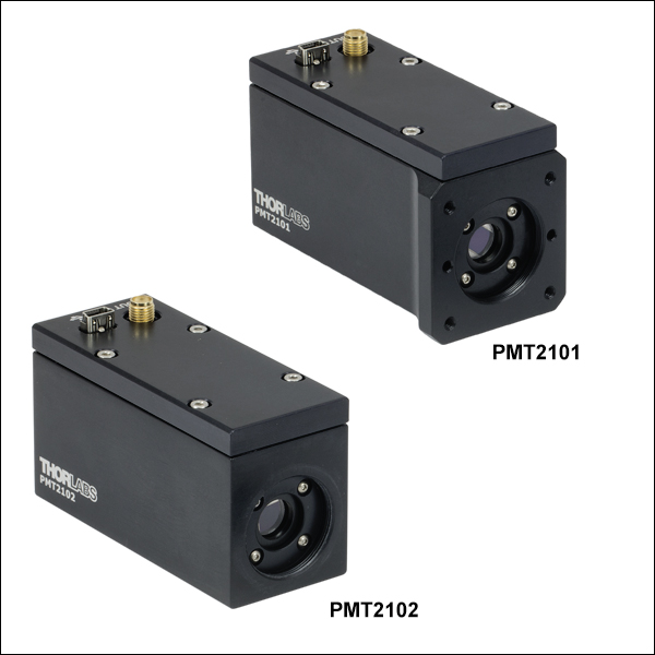
- スペクトル範囲: 300~720 nm
- トランスインピーダンスアンプによる電圧出力
- PMT2101(/M):SM1ネジ付き、30 mmケージキューブに対応、ポスト取付け用のM6タップ穴付き
- PMT2102:Cマウントネジ付き
蛍光実験などで低強度の信号を検出するために、検出部がØ5 mmのGaAsP PMTモジュールをご用意しています。GaAsP光電陰極は可視スペクトルで高い量子効率を持つため、アルカリ金属の光電陰極に比べて入射光への感度が大きくなります(放射感度のグラフは「概要」タブをご覧ください。放射感度は量子効率に比例します)。また、こちらのPMTモジュールは集光角度が広いため、さらに光検出感度が向上します(右図参照)。ただし、高強度の入射光にさらされた場合、アルカリPMTに比べて感度が劣化しやすいのでご注意ください。
こちらのPMTはトランスインピーダンスアンプを内蔵しているため、SMAコネクタからは電圧信号が出力されます。 USB 2.0ミニポートから電力を供給することも可能です。4.5~5.5 V DC、350 mA(典型値)の電源で動作するため、標準のUSBポートをご使用いただけます。当社のソフトウェア(「ソフトウェア」タブ参照)を動作させているPCで制御することも可能で、PC接続用のUSB 2.0アダプターケーブル(A-miniタイプ)も付属しています。こちらのソフトウェアはWindows® 7 または10(64ビット)のPCのみでご使用ください。
こちらのPMTは、2種類のパッケージでご用意しており、幅広い取り付けオプションを実現しています。 PMT2101/MはSM1内ネジ付きで、SM1レンズチューブに接続できます。また、4つの#4-40タップ穴を使用して30 mmケージシステムに取り付けたり、M6タップ穴を使用して当社のØ25 mm~Ø25.4 mm(Ø1インチ)ポストなどに取り付けたりすることもできます。PMT2102はCマウント内ネジ付きで、Cマウントエクステンションチューブに接続できます。
当社ではCマウント付きあるいはSM1ネジ付きPMTと、30 mmケージシステムとSM1レンズチューブによる光学アセンブリを接続するアリ溝アダプタをご用意しております。お手持ちの当社の共焦点および多光子システムへの組み込みをご希望の場合は、当社までご相談ください。
マニュアルに誤りがあります。下記のとおり、訂正させていただきます(マニュアルについては型番横の赤いアイコン
をクリックしてご覧ください)。セクション6.5 Setting the PMT2100 Offset(26ページ)
(誤×)5. Adjust the gain on PMT2100 Control window until the average of all the pixels in the image is 50 - 100.
→(正〇) 5.Adjust the offset on PMT2100 Control window until the average of all the pixels in the image is 50 - 100.

 ズーム
ズーム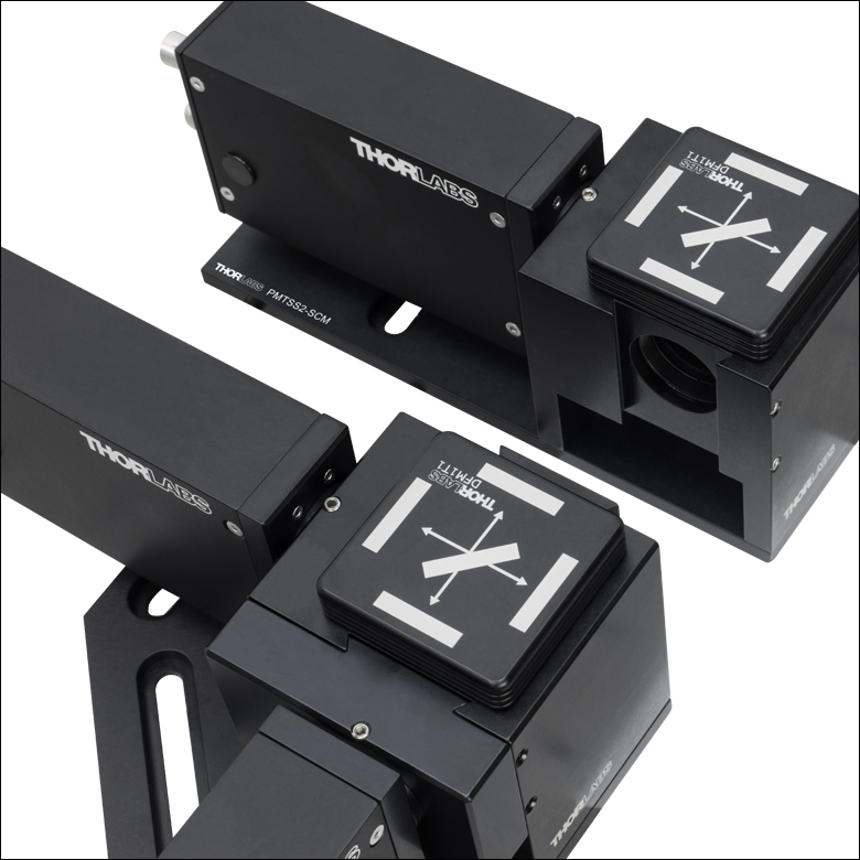
Click to Enlarge
追加チャンネルを簡単に接続可能なインターロック式のアリ溝

Click to Enlarge
ダイクロイックミラーやバンドパスフィルタを保持するための取外し可能なフィルターキューブトップ
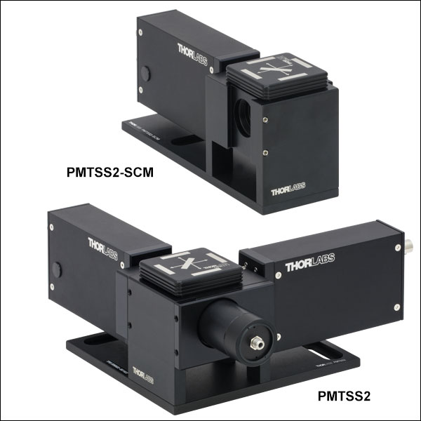
- PMTSS2:2チャンネルPMTモジュール、交換可能な蛍光フィルターキューブインサート付き
- PMTSS2-SCM:追加用1チャンネルPMTモジュール、機械的ならびに光学的アライメント用のアリ溝付き
- SMA905コネクタ付きファイバや自由空間からの入力に対応
- 追加用のフィルターキューブインサートを別途ご用意
2チャンネルモジュールPMTSS2ならびにアドオン式モジュールPMTSS2-SCMは、複数のスペクトルチャンネルに渡る信号の検出が簡単にできるように設計されています。モジュールPMTSS2はPMT(型番PMTSS、詳細は上記参照)が2台と、フィルターキューブトップDFM1T1が組み込まれています。フィルターキューブトップには、1枚のダイクロイックミラー(25 mm x 36 mm)と1枚のバンドパスフィルタ(Ø25 mm)を各光電陰極の前に保持できるため、PMTが検出する波長の選択が可能です。また交換が簡単にきるように、磁石による保持機構が付いています。PMTSS2-SCMは、PMTSS2にアドオンが可能な1チャンネルのモジュールで、PMTが1台と追加のフィルターキューブトップDFM1T1が組み込まれています。
モジュールPMTSS2の入力ポートにはSMA905コネクタ付きのファイバーコリメーターアセンブリが付いており、マルチモードファイバーパッチケーブルまたはバンドルに結合された信号を入力できます。250~1200 nm用のコア径Ø910 µm、NA0.22のSMA905コネクタ付きパッチケーブル(ファイバ素線型番 FG910UEC)がモジュールに付属しています。必要であれば、コリメーターアセンブリを取り外し、モジュールに自由空間の信号を入力することもできます。アセンブリのネジを取り外すと、SM1内ネジが露出し、当社のØ25 mm~Ø25.4 mm(Ø1インチ)レンズチューブを取り付けられるようになります。アドオン式モジュールPMTSS2-SCMにはファイバーコリメーターアセンブリは付属しておりませんが、PMTSS2に付属しているアセンブリを取り付けることが可能です。
PMTSS2-SCMを既存のPMTSS2セットアップに追加できるようにするため、筐体にはインターロック式のアリ溝があり、それによって機械的および光学的なアライメントを行います。取り付け手順は右の動画をご覧ください。取り付けには、2 mmボール(六角)ドライバまたは六角レンチが必要です。付属のファイバ入力アセンブリを使用する場合、ビームが拡散して信号の検出効率を低下させないよう、最大でも8チャンネルまでのご使用をお勧めいたします。自由空間信号を使用する場合、各光電陰極の検出部は3.7 mm × 13.0 mm(H × V)です。
各PMTの出力電流はBNCコネクタから出力されます。トランスインピーダンスアンプは付属しておりませんが、当社では トランスインピーダンスアンプTIA60を別途ご用意しております。各PMTにはそれぞれ別の制御電圧が必要ですが、それらはメス型M8 x 1コネクタより供給します。バイアス制御には+1.20 Vまで供給できる可変電圧電源が必要です(詳細は「グラフ」タブをご覧ください)。モジュールPMTSS2にはリード線付きのオス型M8 x 1コネクタが2つ付属しており、お客様ご自身で適切な低ノイズ電圧電源に接続可能です。アドオン式モジュールPMTSS2-SCMにはコネクタが1つ付属します。
各モジュールには光学テーブルまたはワークステーション取付け用のM6ザグリ穴スロットが付いています。モジュールの重量が大きいので、直接テーブルに取り付けることを推奨しています。PMTは止めネジ(セットスクリュ)を2 mmボールドライバまたは六角レンチで緩めることにより、モジュールのほかの部分から取り外すことができます。
こちらのPMTモジュールには電源は付属しておりません。付属のオス型M8 x 1コネクタに付いているリード線は、電流リミット値を7 mAに設定した+15 VDC電源に接続してください。詳細については「ピン配列」ならびに「発送リスト」のタブをご覧ください。

 ズーム
ズーム
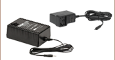
- モジュールPMM01およびPMM02(上記掲載)の交換用電源
- ±12 VDC出力
- 長さ2 mのケーブル、LUMBERG製オス型コネクタRSMV3付き
LDS12Bは±12 VDC出力の安定化電源で、当社のモジュールPMM01およびPMM02にご使用いただけます。LED付きのOn/Offスイッチがあり、入力電圧を100 VAC、120 VAC、または230 VACに切り替えることが可能です。ケーブルに付いているコネクタは3ピンで、グランド用、+12 V用、-12 V用となっています(上図参照)。また、日本国内仕様の電源ケーブルが付属します。
この電源は当社のPDAシリーズの増幅ディテクタ、PDBシリーズの差分フォトディテクタ(バランスディテクタ)、APDシリーズのアバランシェフォトディテクタ、フェムト秒レーザ用オートコリレータFSACにも対応しています。