 Products Home
ピエゾコントローラーKinesis® K-Cube™
- Open-Loop Piezo Driver Supplies up to 150 V
- Seamless Operation with Thorlabs' Piezo Actuators
- Operation via Local Panel Controls or Remote PC via USB
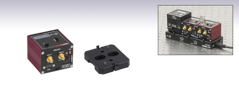
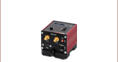
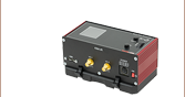
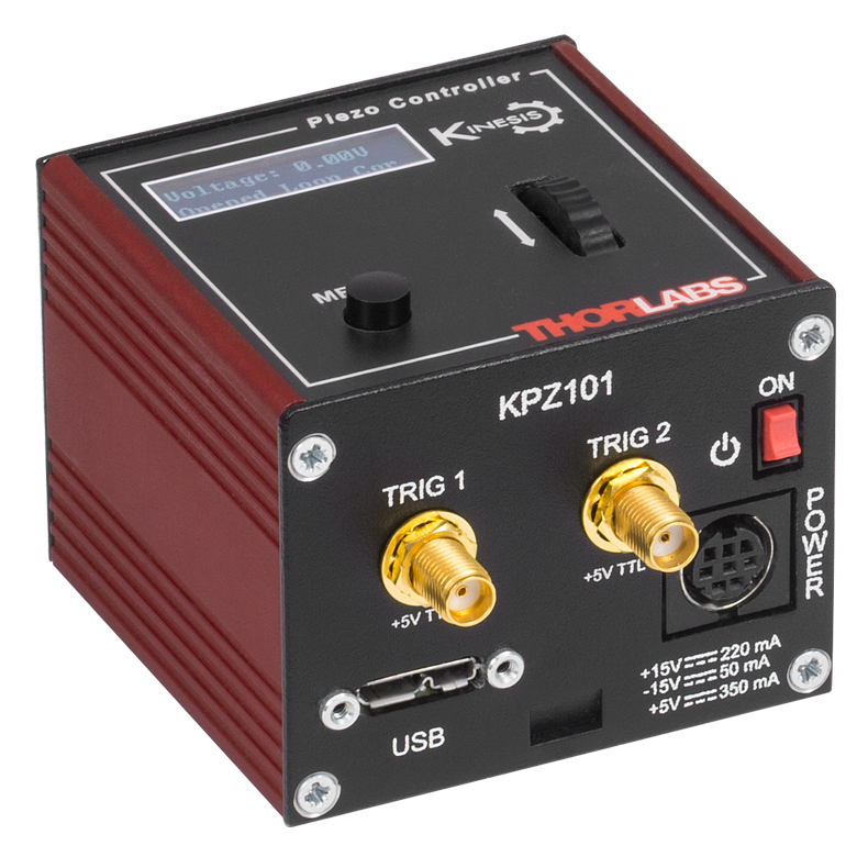
KPZ101
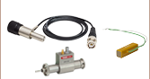
Power Supply
Sold Separately
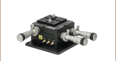
Table Mounting Plate
(Included with the KPZ101)
Application Idea
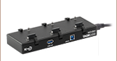
The KPZ101 Piezo Controller can be powered by the KCH301 USB Controller Hub (sold separately) along with two additional K- or T-Cubes.


Please Wait
特長
- コンパクトな設置面積:60 mm x 60 mm x 49.2 mm
- 高電圧出力の選択可能なレンジ:75 V、100 V、150 V
- デジタルポテンショメータにより高電圧の制御を行い、その分解能は調整が可能
- 0~10 Vのアナログ入力(SMAメス型、詳細は「ピン配列」タブをご覧ください)
- モニタ出力(SMAメス型、詳細は「ピン配列」タブをご覧ください)
- 操作しやすい手動制御
- 速度ホイール:速度可変な双方向制御
- デジタル表示メニュー:位置のプリセットとジョグ動作の設定
- ピエゾ走査に適した電圧出力のランプ信号/波形発生機能とトリガ信号の入出力
- Kinesis®またはAPT™制御用ソフトウェア一式(詳細は「モーションコントロールソフトウェア」のタブをご覧ください)
- ソフトウェアは他のKinesisならびにAPTコントローラにも対応しており、統合システムの開発が可能
- シングルならびにマルチチャンネルの電源を別途ご用意
- USBコントローラーハブ(別売り)による多軸拡張も可能
- 磁石と固定用クリップの付いた光学テーブル取付け用アダプタが付属
K-CubeピエゾコントローラKPZ101は、Kinesis®シリーズのコンパクトな高性能モーションコントローラです。このシングルチャンネルのドライバはピエゾ素子の手動制御や自動制御が容易に行えるように設計されています。7.5 mAの電流を最大電圧150 Vまで供給することができ、動作帯域の上限は1 kHzです(「仕様」タブ参照)。このドライバは、当社の様々なチップ型/積層型ピエゾアクチュエータ、ピエゾ組込み型アクチュエータ、ピエゾ駆動ミラーマウント、ピエゾ駆動の1軸および多軸フレクシャーステージなどに対応しています。BNCコネクタの付いたマウントに接続する場合は、BNC-SMCアダプタが必要です。コントローラKPZ101は、ピエゾ慣性モータ付きのアクチュエータやマウントには対応していませんのでご注意ください。それらを駆動するにはピエゾ慣性モーターコントローラが必要です。

ユニットの設置面積は60.0 mm x 60.0 mm x 49.2 mmと非常にコンパクトで、上面パネルのコントローラを使用して手動でモータ位置を調整する際に、システムの近くに配置できるのも便利な点です。テーブル上で操作できると駆動ケーブルの長さを短くでき、ケーブルの管理も容易になります。ユニットの前面には電源スイッチが付いており、このスイッチをオフにするとユーザ設定が保存されます。ユニットの電源を切るときには、必ずこのスイッチをオフにするようにしてください。KPZ101には長さ1.5 mのA-MicroBタイプのUSB 3.0ケーブルが1本付属します。
このK-Cubeは非常にコンパクトながら、すべてのピエゾ制御機能を搭載しています。また、幅広い種類のピエゾ素子をサポートするために、出力のレンジは75 V、100 V、150 Vから選択できます。デジタルコード化された調整用ポテンショメータには十分な分解能があり、精密な位置制御のための調整が容易です。高電圧出力の直接的な制御は、アナログ入力コネクタ(0~10 V)を使用して行うことができます。一方、低電圧出力コネクタをオシロスコープなどにつなげば、高電圧出力をモニタできます。プログラム可能な波形生成機能とトリガ信号の入出力機能を合わせ持っているため、このユニットはピエゾ走査用に非常に適しています。
USB接続によるプラグアンドプレイが可能で、PC制御による操作が容易です。ソフトウェアプラットフォームとしては、当社の新しいKinesisソフトウェアパッケージと従来のAPT(Advanced Positioning Technology)ソフトウェアパッケージの2種類をご用意しております。Kinesisソフトウェアでは新しい.NETコントロールが使用でき、最新のC#、Visual Basic、LabVIEW™、あるいはその他の.NETに対応する言語を使用してカスタムプログラムを作成するようなサードパーティの開発者も利用することができます。当社の従来のAPTソフトウェアを使用した場合は、ActiveX®プログラミング環境を利用して複雑な動作シーケンスを素早く設定できます。例えば、当社のステージならびにアクチュエータ製品の動作パラメータは、すべてソフトウェアにより自動的に設定されます。これらのソフトウェアパッケージの詳細については、「モーションコントロールソフトウェア」ならびに「APTチュートリアル」タブをご覧ください。
光学テーブル取付け用プレート
各ユニットには、コントローラのベース部分をクリップで固定できる取付けプレートが付属します。プレートには2つの磁石が付いており、光学テーブルに一時的に設置する際にご使用いただけます。また、2つのM6キャップスクリュ用ザグリ穴は、恒久的に取り付ける際にご使用ください。光学テーブル取付け用プレートの図面は「仕様」タブ、取付け方法は「取付けオプション」タブでご覧いただけます。
電源の選択
必要な電源(シングルチャンネル、マルチチャンネル、あるいはハブベース)は、その用途とお客様が対応可能な電源をお持ちかどうかに依存します。そのような理由と当社の環境イニシアチブにより、当社では電源をセット販売しておりません。そうすることで、例えばマルチチャンネルやハブをベースとしたシステムが適切な場合に、不要なシングルチャンネルの電源を受け取るようなことは無くなり、コストや煩わしさが省けます。
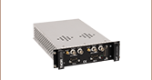
多軸のモーションコントロールの用途では、USBコントローラーハブKCH301またはKCH601(下記参照)をご使用になると、複数のユニットを1台のPCに接続することができます。KCH301は、最大3台のT-CubeまたはK-Cubeコントローラが取り付けられます。右の写真にあるKCH601は、最大6台まで使用可能です。
モーターコントローラKPZ101に対応する電源は下記のとおりです。
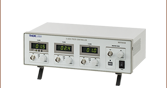
| Other Piezo Driver Controllers | ||||
|---|---|---|---|---|
| K-Cube Controller Single Channel | K-Cube Combined Piezo Controller and Strain Gauge Reader Single Channel | Open Loop Benchtop Controller 1 and 3 Channel | Closed Loop Benchtop Controller 1 and 3 Channel | Rack System Module 2 Channel |
| KPZ101 Specifications | |
|---|---|
| Piezoelectric Output | |
| Drive Voltage (SMC Male) | 0 - 150 V (SMC Male Connector) |
| Maximum Drive Current (Continuous) | 7.5 mA |
| User Voltage Control | Digital Potentiometer (Resolution Selectable) |
| Stability | 100 ppm Over 24 hrs (After 30 min Warm-Up) |
| Output Noise | No Load: < 5 mVRMS 3.6 µF Load: < 3 mVRMS |
| Typical Piezo Capacitance | 1 - 10 µF |
| Drive Bandwidth | 1 kHz (1 µF Load, 1 Vp-p) |
| Drive Input (SMA Female) | 0 - 10 V |
| Output Monitor (SMA Female) | 0 - 10 V |
| T-Cube Controller Hub Connector | 26-Way ERNI |
| General | |
| Input Power Requirements | +15 V @ 220 mA -15 V @ 50 mA +5 V @ 350 mA |
| USB Connector Type | USB 3.0 |
| USB Connection Speed | USB 1.1 Full Speed (12 Mbps) |
| Housing Dimensionsa (W x D x H) | 60.0 mm x 60.0 mm x 49.2 mm (2.36" x 2.36" x 1.94") |
| Compatible Thorlabs Stages and Actuators | |
|---|---|
| Translation Stages | 3-Axis and 6-Axis Nanopositioners, NF15AP25, NFL5DP20, NFL5DP20S |
| Piezo Controlled Mountsa | KC1-P, KC1-PZ, POLARIS-K05P2, POLARIS-K1S3P, POLARIS-K1S2P, POLARIS-K2S2P |
| Bare Piezos | Piezo Chips and Stacks with Drive Voltages up to 150 V |
| Actuators | DRV120, PE4a, DRV517, PK2FSF1, PK2FVF1, PAS005, PAS009, PAZ005, PAZ009 |

Click to Enlarge
KPZ101と付属の光学テーブル用アダプタの図面

電源コネクタ
ミニDINメス型
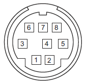
| Pin | Description | Pin | Description |
|---|---|---|---|
| 1 | +5 V | 6 | Common Ground |
| 2 | +5 V | 7 | Common Ground |
| 3 | -15 V | 8 | Common Ground |
| 4 | +15 V | Shield | Common Ground |
| 5 | +5 V |
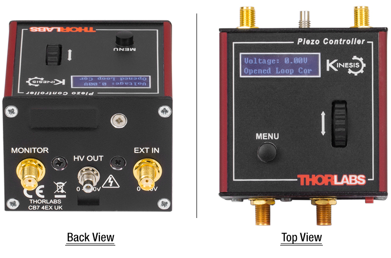
PC接続用コネクタ*
*このUSBポートはUSB3.0対応ですが、USB2.0でもご使用いただけます。USB 2.0 を使用する際は、Micro-Bタイプコネクタを上図の網掛け部分に接続します。 KPZ101にはAタイプ-MicroBタイプのUSB 3.0ケーブルが1本付属します。
MonitorSMAメス型 | EXT INSMAメス型 | HV OUTSMCオス型 | TRIG 1SMAメス型 | TRIG 2SMAメス型 |
 | | | | |
| この低電圧(0~+10 V)の出力端子は、HV OUT高電圧出力端子の信号のモニタに使用できます。 一般的な用途では、オシロスコープに直接接続し、波形や高電圧出力での電圧レベルがモニタできます。 | 外部アナログ信号源に接続して、キューブの動作制御に使用します。 入力電圧範囲は0~+10 Vで、入力インピーダンスは12 kΩです。 | 0~150 V、0~7.5 mA。 駆動信号をピエゾアクチュエータに送ります。 最大電圧(75 V、100 Vまたは150 V)は前面パネルで設定します。 | +5 V TTL | +5 V TTL |
| これらのコネクタからは5 Vのロジックレベルの信号を入出力します。トリガ信号を外部機器に出力する、あるいは外部機器から入力するかについては設定することができます。ロジックレベルの調整や、トリガ信号の入力あるいは出力の設定は、それぞれのポートごとに独立に行うことが可能です。 | ||||
K-Cube取付けオプション
K-Cubeコントローラの光学テーブルへの固定方法を2種類ご用意しております。1つは光学テーブル取付けプレートで、すべてのK-Cubeに付属しており、1台のコントローラを光学テーブルに取り付けることができます。もう1つは、3ポートあるいは6ポートのUSBコントローラーハブ(別売り)で、当社のK-Cubeコントローラを取り付け、それらに電力を供給することができます。詳細は下記をご覧ください。
光学テーブル取付けプレート
各ユニットには、コントローラのベース部分をクリップで固定できる取付けプレートが付属します(右の動画参照)。プレートには2つの磁石が付いており、光学テーブルに一時的に設置する際にご使用いただけます。また、2つのM6キャップスクリュ用ザグリ穴は、恒久的に取り付ける際にご使用ください。光学テーブル取付けプレートの図面は「仕様」タブでご覧いただけます。
Kinesis USBコントローラーハブ
USBコントローラーハブKCH301やKCH601を用いると、複数のユニットを取り付けて、それらを1台のPCに接続することができます。 コントローラーハブは、3台(KCH301)もしくは6台(KCH601)のK-CubeやT-Cubeをサポートするハブ部分と、壁コンセントに接続して電力を供給する電源部分から構成されています。K-Cubeはユニットについているクリップで簡単にハブに取り付けられますが、T-Cube(現製品および旧製品)の取り付けには、上の動画のようにアダプタープレートKAP101が必要です。 複数のコントローラをお使いになるときには、ハブをご使用になるとUSB用と電源用のケーブル本数を大幅に削減することができます。
K-Cube用光学テーブル取付けプレート
T-Cubeと違い、すべてのK-Cubeには、コントローラのベース部分をクリップで固定できる取付けプレートが付属します。プレートには2つの磁石が付いており、光学テーブルに一時的に設置する際にご使用いただけます。また、2つのM6キャップスクリュ用ザグリ穴は、恒久的に取り付ける際にご使用ください。
Kinesis USBコントローラーハブ
3ポートまたは6ポートのUSBコントローラーハブを用いると、多軸の操作をする際に複数のコントローラを1台のPCに接続することができます。K-Cubeはハブに直接取り付けられますが、T-Cubeの取り付けにはアダプタープレートKAP101が必要です。
Click for Details
閉ループシステムの一部として用いたピエゾコントローラ
ビーム安定化用セットアップ内のピエゾコントーラ
実験におけるセットアップでは、ビームドリフト(意図しないビーム偏差)を補正するため、アクティブなビームの安定化という方法が用いられます。ドリフトは、取り付けが不安定な光学素子やレーザ光源の不安定性、あるいはオプトメカニクスのセットアップにおける熱変動などによって発生することがあります。ビームのアクティブな安定化は、セットアップエラーを修正するだけでなく、例えばレーザの高い出力を維持するためにレーザーキャビティの内部で用いたり、光学テーブル上で長時間にわたり常に一定の光照射を必要とする測定などで用いたりしています。長い光路のセットアップでも、ビームのアクティブな安定化を図ることは有効です。小さな角度偏差が長い光路の先では著しい変位につながるからです。
左の図はビーム安定化のセットアップ例を示しています。光路に置かれたビームスプリッタにより、サンプルビームが4分割位置センサに送られます。4分割位置センサは、ディテクタの中央に対するビームの変位をモニタします。(適切に安定化するためには、ビームスプリッタはできるだけ測定位置の近くに配置してください)。4分割ディテクタは、ビームの変位量に比例したX方向ならびにY方向のエラー信号を出力します。各エラー信号はピエゾコントローラの各チャンネルに送られ、ピエゾコントローラはビームがクォドラントセンサの中央にくるようにビームを動かします。
ここに描かれたセットアップはビームを空間の1点に安定化しています。光路にわたってビームを安定化させるには、4つの独立した出力チャンネル(つまり少なくとも4台のピエゾコントローラ)、2つのピエゾアジャスタ付きのミラーマウント、2つの位置センサ、および2台の位置センサーコントローラが必要です。ビーム安定化のセットアップ用として推奨する部品を下記の表に記載しています。
| Suggested Components | |
|---|---|
| Description | Item # |
| Piezoelectric Controller | KPZ101 T-Cube Piezo Controllera |
| Mirror Mount with Piezo Adjusters (Choose One) | POLARIS-K1S3P Polaris® Mirror Mount with 3 Adjusters, POLARIS-K1S2P Polaris® Mirror Mount with 2 Adjusters, KC1-PZ (KC1-PZ/M) Mirror Mount, or KC1-T-PZ (KC1-T-PZ/M) Mirror Mount with SM1-Threaded Bore |
| Position Detector | PDP90A (320 - 1100 nm), PDQ80A (400 - 1050 nm), or PDQ30C (1000 - 1700 nm) |
| K-Cube Position Sensor Controller | KPA101 |
| K-Cube vs. T-Cube Feature Comparison | ||
|---|---|---|
| Feature | KPZ101 K-Cube | TPZ001 T-Cube |
| Kinesis Software Compatibility | ||
| APT Software Compatibility | ||
| Kinesis USB Controller Hubs Compatibility | Requires KAP101 Adapter | |
| TCH002 T-Cube USB Controller Hubs Compatibility | N/A | |
| Power Switch | N/A | |
| Bidirectional SMA Trigger Porta | 2 | N/A |
| SMA Monitor Outputa | ||
| SMA External Analog Inputa | ||
| Computer Connectiona | USB 3.0 Micro B (USB 2.0 Compliant) | USB 2.0 Micro B (USB 2.0 Compliant) |
| Included Mounting Plate | ||
| Size (L x W x H) | 60.0 mm x 60.0 mm x 49.2 mm (2.36" x 2.36" x 1.94") | 60.0 mm x 60.0 mm x 49.2 mm (2.36" x 2.36" x 1.94") |
| On-Unit Digital Display Menu | ||
| Set Open/Closed Loop | ||
| Go To Voltage | Only via Software | |
| Voltage Range and Control | ||
| Joystick Mode | Only via Software | |
| Jog Voltage Step Size | Only via Software | |
| Teach Voltage | Only via Software | |
| Screen Brightness | ||
| Disable Movement | N/A | |
| Stage Select | Only via Software | |
Kinesis®モーションコントローラのご紹介
旧世代のT-Cube製品から大幅に改良されたK-Cubeのラインナップでは、新しいKinesis ソフトウェアの導入だけでなく、物理的設計やファームウェアの全面的な見直しも行い、汎用性を高めています。
すべてのK-Cubeコントローラにはデジタルディスプレイが付いています。このディスプレイは基本的な入出力情報の表示を行うだけでなく、指定位置への移動コマンドや、ホーミング、速度制御、ジョグ動作などを含む様々なメニューオプションの選択機能も備えています。ユニットの速度ホイールとメニューボタンを使用して、利用可能な機能をスクロールしてご覧いただくことができます。各ユニットには電源スイッチがあり、これをオフにするとお客様が調整した設定はすべて保存されます。また、5 V TTLロジック信号を入出力する双方向性SMAトリガーポートが2つ付いています。
右の表では、K-Cube KPZ101と旧世代のT-Cube TPZ001の2種類のモーションコントローラの機能を比較しています。
Click to Enlarge
K-Cube KinesisピエゾコントローラKPZ101
Kinesis USBコントローラーハブ
Kinesis USB 2.0コントローラーハブは、K-Cubeコントローラの機能を補完する製品です。USBハブには3台用と6台用の2種類があり、複数のK-CubeやT-CubeのコントローラがホストPCと通信できるように設計されております。これらのハブはT-Cube製品との後方互換性があります。
K-Cubeはユニットについているクリップで簡単にハブに取り付けられますが、T-Cube(現製品および旧製品)の取り付けには、右下の動画のようにアダプタープレートKAP101が必要です。 複数のコントローラをお使いになるときには、ハブをご使用になるとUSB用と電源用のケーブル本数を大幅に削減することができます。
K-Cube用光学テーブル取付けプレート
T-Cubeとは異なり、すべてのK-Cubeにはコントローラのベース部分をクリップで固定できる取付けプレートが付属します。プレートには2つの磁石が付いており、光学テーブルに一時的に設置する際にご使用いただけます。また、2つのM6キャップスクリュ用ザグリ穴は、恒久的に取り付ける際にご使用ください。
Kinesis USBコントローラーハブ
3ポートまたは6ポートのUSBコントローラーハブを用いると、多軸の操作をする際に複数のコントローラを1台のPCに接続することができます。K-Cubeはハブに直接取り付けられますが、T-Cubeの取り付けにはアダプタープレートKAP101が必要です。
当社では幅広い種類のモーションコントローラを駆動できるよう、Kinesis® ソフトウェアパッケージと従来のAPT™(Advanced Positioning Technology)ソフトウェアパッケージの2種類のプラットフォームをご用意しております。どちらのパッケージも小型で低出力のシングルチャンネルドライバ(K-Cube™やT-Cube™など)から高出力でマルチチャンネルのモジュール式19インチラックナノポジショニングシステム(APTラックシステム)まで幅広い種類のモーションコントローラをカバーするKinesisシリーズのデバイスを制御できます。
Kinesisソフトウェアには、最新のC#、Visual Basic、LabVIEW™またはその他の.NETに対応する言語を使用してカスタムプログラムを作成するサードパーティの開発者向けに、.NETコントロールが付属しています。また、.NETフレームワークを使用しない用途向けに低級言語用のDLLライブラリも付いています。センターシーケンスマネージャが、当社の全てのモーションコントロールハードウェアの統合と同期をサポートします。

KinesisのGUIスクリーン
APTのGUIスクリーン
当社従来のAPTシステムソフトウェアプラットフォームは、C#、Visual Basic、LabVIEWまたはその他のActive-Xに対応する言語を使用してカスタムプログラムを作成するサードパーティの開発者向けに、ActiveXをベースとしたコントロールが付属しています。また、ハードウェア無しでカスタムプログラムの開発を行うためのシミュレーターモードも付いています。
これらの共通のソフトウェアプラットフォームにより、あらゆるKinesisとAPTコントローラをシングルアプリケーションに簡単に組み込むことができます。ソフトウェアツールは1セット習得するだけで共通した操作が可能です。シングルチャンネルシステムからマルチチャンネルシステムまで、あらゆるコントローラを組み合わせ、全てを1台のPCのソフトウェアインターフェイスから制御することが実現可能です。
このソフトウェアパッケージを使用するには2つの手段があります。GUI(グラフィカルユーザーインターフェイス)ユーティリティを使用したコントローラとの直接対話ならびに「out of the box」コントロール、またはご選択の開発言語でカスタム統合の位置決めやアライメントソリューションを簡単にプログラムできる一連のプログラミングインターフェイスです。
APTシステムソフトウェアをよりご理解いただけるために様々なチュートリアルビデオもご用意しております。ビデオではソフトウェアの概要とAPT Configユーティリティをご説明しています。また、ソフトウェアのシミュレーターモードを利用すると、コントローラを接続しないでソフトウェアを試すことができます。その方法を説明したビデオもあります。これらのビデオは「APTチュートリアル」タブ内のリンクからご覧いただけます。
ソフトウェア
Kinesis バージョン 1.14.47
このKinesisソフトウェアパッケージには、当社のKinesisならびにAPT™システムコントローラを制御するためのGUIが含まれています。
下記もご用意しております:
- 通信プロトコル
ソフトウェア
APT バージョン 3.21.6
このAPTソフトウェアパッケージには、当社のAPT™およびKinesisシステムコントローラを制御するためのGUIが含まれています。
下記もご用意しております:
- 通信プロトコル
Kinesis®ソフトウェアでは新しい.NETコントロールが使用でき、最新の最新のC#, Visual Basic, LabVIEW™、ほかの.NET対応言語を使用する開発者がカスタムにプログラムを作成することもできます。
C#
このプログラミング言語はマルチプログラミングパラダイムやマルチプログラミング言語が使用可能となるよう設計されているため、複雑な問題が簡単かつ効率的に解決できます。型付け、命令型、宣言型、関数型、ジェネリック、オブジェクト指向、そしてコンポーネント指向が含まれます。 この共通のソフトウェアプラットフォームにより、1セットのソフトウェアツールを習得するだけで、あらゆるKinesisコントローラを簡単に組み合わせることができます。このようにして1軸システムのコントローラから多軸システムのコントローラまで、様々なコントローラを組み合わせ、全てを1台のPCのソフトウェアインターフェイスから制御することが可能となりました。
Kinesisシステムソフトウェアを使用するには2つの手段があります。コントローラを直接つないで制御を行なう付属のGUI(グラフィカルユーザーインターフェイス)ユーティリティ、またはご希望の開発言語でカスタム仕様の位置決めやアライメントを簡単にプログラムできる一連のプログラミングインターフェイスです。
Kinesisモーションコントロールライブラリの構築の参考となる実行可能なプロジェクト機能拡張例については下のリンクをクリックしてください。なお、Quick Startのプロジェクト例の実行には別の統合開発環境(IDE)(Microsoft Visual Studioなど)が必要です。C#のプロジェクト例はKinesisソフトウェアパッケージに付属する.NETコントロールで実行可能です(詳細は「Kinesisソフトウェア」タブをご覧ください)。
 | Click Here for the Kinesis with C# Quick Start Guide Click Here for C# Example Projects Click Here for Quick Start Device Control Examples | |
LabVIEW
LabVIEWは、.Netコントロールを介してKinesisまたはAPTベースのコントローラとの通信に使用できます。LabVIEWでは、ツールとオブジェクトでフロントパネルとして知られるユーザーインターフェイスを構築した後、グラフィカル表記の関数を使ってコードを追加し、フロントパネルのオブジェクトを制御します。下記のLabVIEWチュートリアルでは.Netコントロールを使用してLabVIEW内KinesisまたはAPT駆動デバイス用の制御GUIを作成するための情報をご提供しています。 LabVIEWでコントローラを制御する基本的な方法や、LabVIEW GUIを用いてデバイスを操作する前に行うべき設定の手順についても解説しています。
 | Click Here to View the LabVIEW Guide Click Here to View the Kinesis with LabVIEW Overview Page | |
こちらのページでご覧いただくAPTビデオチュートリアルは、付属のATPユーティリティに関する説明と、いくつかのプログラミング環境におけるAPTシステムのプログラミングに関する説明の2つの部分から構成されています。
免責事項:これらの動画は、当初はAdobe Flashによって作成されました。2020年のAdobe Flashのサポート終了後、これらのチュートリアルは再録画されています。各動画の下にはFlash Playerの操作ボタンが見えますが、機能はしません。
APTコントローラには、APTUserユーティリティとAPTConfigユーティリティが付いています。APTUserを用いると、直感的操作が可能なグラフィック制御パネルを介して、APTで制御するハードウェアに素早く簡単に接続することができます。APTConfigは「オフライン」ユーティリティで、メカニカルステージのタイプを事前に選択し、それらを特定のモーションコントローラに対応付けるなど、システム全体のさまざまな設定を行うことができます。
APT Userユーティリティ
下の左側の動画では、APTUserユーティリティの操作概要について説明しています。シングルチャンネルコントローラのOptoDriverは、制御用のPCが無くても前面パネルのコントローラを介して操作できます。前面パネルのコントローラに保存されている操作に関する設定は、APTUserユーティリティを使用して変更することができます。そのプロセスは下の右側の動画でご覧いただけます。
APT Configユーティリティ
シミュレートされたハードウェア構成のセットアップや、メカニカルステージの特定のモータードライブチャンネルへの対応付けなど、APT Configユーティリティを使用してAPTシステム全体の様々な設定ができます。下の最初の動画ではAPT Configの概要をご覧いただけます。シミュレートされたハードウェア構成の作成方法やステージと対応付ける方法についての詳細は、その右側の2つの動画でご覧いただけます。
APTのプログラミング
APTソフトウェアシステムは、ActiveXコントロールのコレクションとして実装されています。ActiveXコントロールは言語に依存しないソフトウェアモジュールで、グラフィカルユーザーインターフェイスとプログラミングインターフェイスの両方を提供します。ハードウェアユニットのタイプごとにActiveXコントロールのタイプがあります。例えば、Motor ActiveXコントロールはすべてのタイプのAPTモーターコントローラ(DCまたはステッパ)の操作に対応します。ActiveXコントロールは多くのWindowsソフトウェア開発環境やソフトウェア言語で直接サポートされており、そのようなコントロールがカスタムアプリケーションに組み込まれると、そこに含まれるすべての機能が即座にアプリケーションで利用できるようになります。下の動画では、LabVIEW、Visual Basic、Visual C++によるAPT ActiveXコントロールの基本的な使用方法について説明しています。これ以外に、LabWindows CVI、C++ Builder、VB.NET、C#.NET、Office VBA、Matlab、HPVEEなどの多数の言語でもActiveXはサポートされています。これらの言語環境についてはチュートリアルのビデオでは特に取り上げていませんが、動画内の考え方の多くは他の言語環境でも適切に使用できます。
Visual Basic
Part 1ではVisual Basicで動作するAPT ActiveXコントロールを設定する方法について説明しており、Part 2では独自の位置決めシーケンスをプログラミングする方法について説明しています。
LabVIEW
LabVIEWはActiveXをフルサポートしています。下の一連のチュートリアルビデオでは、APTによる独自のモーションコントロールシーケンスを作製する際の基本的な構成要素を示しています。まずソフトウェア開発中にオンラインヘルプを呼び出す方法をご紹介します。Part 2ではAPT ActiveXコントロールの作成方法をご紹介します。ActiveXコントロールではメソッド(機能)とプロパティ(数値設定)の両方を設定できます。Part 3と4では、ActiveXコントロールで示されたメソッドとプロパティを作成してワイヤで接続する方法をご紹介します。最後に、Part 5では全体をまとめて、独自の移動シーケンスを実行するLabVIEWのプログラム例をご紹介します。
Part 1:オンラインヘルプへのアクセス方法
Part 2:ActiveXコントロールの作成方法
Part 3:ActiveXのメソッドの作成方法
Part 4:ActiveXのプロパティの作成方法
Part 5:ActiveXコントロールの開始方法
下のチュートリアルビデオでは、メソッドおよびプロパティのノードを作成する別の方法について説明しています。
ActiveXメソッドの作成方法(別の方法)
ActiveXプロパティの作成方法(別の方法)
Visual C++
Part 1ではVisualC++で動作するAPT ActiveXコントロールを設定する方法について説明しており、Part 2では独自の位置決めシーケンスをプログラミングする方法について説明しています。
MATLAB
当社のAPTポジショナにMATLABおよびActiveXコントロールを使用する場合は、こちらの資料をご覧ください。
プログラマー向けとして、LabVIEWでAPTソフトウェアをプログラミングする方法もこちらからご覧いただけます。
ピエゾアクチュエータの帯域幅に関するチュートリアル
多くの高速用途では、ピエゾ素子の形状変化する速度を知ることが必須となります。 ピエゾコントローラとピエゾ積層の帯域幅は、下記の数値がわかることで、計算で求められるようになります。
- コントローラが供給可能な最大電流量。下記で例としてとりあげられているBPCシリーズのピエゾコントローラでは、この数値は0.5 Aです。
- ピエゾ素子の負荷容量。容量が大きいほどシステムは遅くなります。
- 信号振幅の最適値(V)。この振幅がピエゾ素子の伸長寸法を決定します。
- ドライバの最大帯域幅。この数値は駆動負荷に依存しません。
出力コンデンサを駆動する際には、帯電と放電にそれぞれ電流が必要です。 帯電電荷の変化dV/dtはスルーレートと呼ばれています。 静電容量が大きいほど、必要とされる電流量は大きくなります。
例えば100 µmのピエゾ積層において静電容量が20 µFで、最大電流量が0.5 AのBPCシリーズピエゾコントローラで駆動されるとき、スルーレートは下記の数式で求められます。
したがって電圧が瞬間的に0 V から75 Vに変化するとき、出力電圧が75 Vに達するには3 msかかります。
注記: これらの計算式においては、ドライバの最大帯域幅は計算によって得られる帯域幅よりもずっと大きな値であり、ドライバの帯域幅は制限要因とならないことを前提としています。 なおこれらの数式が、開ループシステムにしか適用できない点にご注意ください。 閉ループモードでは、フィードバックループの応答の遅延がさらに帯域幅を制限します。
正弦波信号
システムの帯域幅は、通常は所定の振幅の正弦信号に対するシステムの応答により規定します。 正弦信号のピーク振幅がA、ピーク‐ピーク電圧がVpp、そして周波数がfの条件で駆動されているピエゾ素子については、以下の数式が成立します。
右の図は、時間の経過とともに変化する電圧を表しています。 スルーレートの最大値、または電圧の最大の変化は、t = 2nπ, (n=0, 1, 2,...)が成立する時点となり、右図では点 aで示されています。

上記の数式から下記が導出できます。

それゆえに下記が成立します。
上記の例では最大電圧(75 V)での帯域幅は下記の値になることがわかります。
 .
.
ピエゾが小さく、静電容量が1/10になると、結果は10倍向上して約1060 Hzとなります。 また、積層が100 µmのままであっても、ピーク‐ピーク電圧が7.5 V(10% の最大振幅値)であれば、結果は同様に10倍向上して約1060 Hzとなります。
三角波信号
ピエゾアクチュエータが三角波で駆動される場合、最大電圧がVpeakで、最小電圧が 0の時、スルーレートは勾配もしくは下記に等しくなります。
![]() .
.
あるいはf = 1/Tであるので、下記が導出できます。
矩形波信号
ピエゾアクチュエータが矩形波で駆動される場合、最大電圧がVpeakで、最小電圧が 0の時、スルーレートが最小の立ち上がりと立ち下がりの数値を制限します。この条件では、信号の立ち上がりまたは立ち下がりの途中では、スルーレートは勾配に等しくなります。 trが最小立ち上がり時間であるとき、下記の数式が成り立ちます。
この式により、下記の数式が成立することもわかります。
 .
.
ピエゾの動作や理論についてはピエゾ素子のチュートリアルをご参照ください。
| Posted Comments: | |
xm dou
(posted 2024-03-15 10:50:04.247) KPZ101与KSG 101闭环使用时,可以通过软件输入位置(单位微米)实现对压电驱动器的位置控制,而不是输入行程的百分比?
另外,0位移对应不是0%的行程,大约是8%,闭环时无法设置0%行程, cstroud
(posted 2024-03-28 10:50:48.0) Thanks for reaching out. When using the KPZ101 together with the KSG101 in closed loop mode, you aren't able to control the travel of the piezo by entering a position in microns. The KSG will display what the current position is and you will be able to adjust the voltage applied and the percentage of travel. The percentage of travel also ranges from around 8% to 88%, this is calibrated so that if the piezo travels below 0 or above the maximum range, it will not hit a limit switch. Ivan Zorin
(posted 2024-01-17 10:16:29.25) Dear Madam or Sir,
I didn't find a useful information on the webpage. Is there a way to control KPZ101 in the python? It would be important as the other key parts of the software are built in python.
Best regards,
Ivan cstroud
(posted 2024-01-18 06:22:38.0) Thanks for reaching out. Our motion controllers use .Net DLL's that can be controlled with Python using Pythonnet. I will reach out to you directly to send over some examples. user
(posted 2022-07-06 22:02:33.367) Hi. I would like to ask about the voltage input over the range (0 V to 10 V) for KPZ101.
I have a circuit with the output voltage of -13.5 V to 13.5 V and would like to amplify the voltage with KPZ101. The circuit will operates 0 V to 10 V, but it may exeed the range.
Is it has a protection circuit for such voltage? (13.5 V, -13.5 V) cilong zhang
(posted 2022-04-01 11:22:56.727) I recently bought the K-Cube piezo controller but I can only seem to change the voltage at a rate of 2 Hz using Kinesis software. I was expecting to drive the piezo faster, How can i do so? Thanks!!! cwright
(posted 2022-04-01 06:28:16.0) Response from Charles at Thorlabs: Thank you for your query. The frequency which can be achieved when driving a piezo is dependent on the capacitance of the piezo and the current supply of the controller. There is more information in our bandwidth tutorial here: https://www.thorlabs.de/newgrouppage9.cfm?objectgroup_id=2421&tabname=Piezo%20Bandwidth. Technical support will reach out to you to discuss your application. user
(posted 2021-09-15 06:15:18.36) Please could you tell me what the functional differences are between the K-Cube™ Piezo Controller KPZ101 and the more expensive MDT694B Single Channel, Open-Loop Piezo Controller. The K-cube looks to have better software interface using Kinesis for easy control, but otherwise I can't see other obvious differences.
I will be using the the controller to drive the amplified piezoelectric actuator APF710 at varying frequencies. I'd be using either software or a function generator to produce sinusoidal inputs. cwright
(posted 2021-09-16 08:11:37.0) Response from Charles at Thorlabs: Thank you for your query. The main differences are that the KPZ101 has a lower maximum drive current and a lower bandwidth. It is however more compact, can be triggered by other devices and has support for closed loop control when used with a strain guage reader. Vincent Gosselin
(posted 2021-06-22 15:08:57.91) Kinesis® K-Cube™ Piezo Controller
Hi Thorlabs,
I recently bought the K-Cube piezo controller but I can only seem to fully extend and retract the piezo at a rate of 2 times a second using Kinesis software. I was expecting to drive the piezo in the KHz range...
How can i do so?
Thanks!!!
Vincent jcater
(posted 2021-06-23 09:43:09.0) Response from Jack at Thorlabs: The drive bandwidth will depend on the load capacitance of the Piezo, a graph on this can be found here https://www.thorlabs.com/images/TabImages/KPZ101_Frequency_Response_780.gif.
To drive the piezo at these frequencies you can either use the Kinesis sequencer to set the voltage to 0V and then 75/150V and add a wait time between these to allow the piezo to fully extend and retract. Alternatively you could use the EXT IN on the KPZ101 to drive the piezo element at 1kHz if the piezo capacitance is 1µF. user
(posted 2021-04-22 05:51:32.863) Hi there,
We recently ordered KPZ101 and KSG101 controllers, but they seem to get quite hot even when they are idling.
Just want to check whether this is normal? Because we have six of them mounted on the KCH601 hub, I wonder if this heat accumulation could cause long-term instability if the heat does not dissipate efficiently?
Many thanks in advance. cwright
(posted 2021-04-23 03:18:20.0) Response from Charles at Thorlabs: Hello and thank you for your query. The cubes are expected to get warm while idling and we use several such cubes on a KCH601 in our AFM educational kit so you should not experience issues. Joseph Natal
(posted 2020-02-16 23:41:06.21) Hello! I am wondering if there is any C or C++ API for this single channel piezo controller. I am a member of Lawrence Berkeley National Lab and UC Berkeley, working on a research/course project.
Thanks,
Joseph Natal cwright
(posted 2020-02-18 08:05:06.0) Response from Charles at Thorlabs: Hello Joseph, there is indeed a C API for this. If you download our Kinesis software at the address below you will find the file "Thorlabs.MotionControl.C_API" in the installation directory. By default this will be C:\Program Files\Thorlabs\Kinesis
https://www.thorlabs.com/software_pages/ViewSoftwarePage.cfm?Code=Motion_Control 2693502986
(posted 2018-11-07 10:14:17.773) “HV OUT”接口为公头极易损坏,针脚容易折断断,在实验中造成了的严重的不便和经济损失。与Polaris系列光学调整架配套使用时没有配套线缆,十分不便。 llamb
(posted 2018-11-07 11:02:22.0) Thank you for your feedback. Broken connector pins are typically attributed to over-stressing the cable connections, as we have not commonly seen these break very easily. I will reach out to you directly to troubleshoot and see if the delivered product was faulty. If faulty, we will gladly offer a replacement.
For connecting the cables included with the Polaris piezo mounts to the KPZ101 controller, you can use our T4292 adapter. We are looking into the possibility of providing SMB to SMC cables for direct use of the Polaris piezo mounts with the KPZ101 as well.
Also, you may email 'techsupport-cn@thorlabs.com' directly with future inquiries.
感谢您的反馈意见。 断开的连接器引脚通常归因于对电缆连接的过度应力,因为我们通常不会看到它们很容易断裂。 我会直接联系您进行故障排除,看看交付的产品是否有问题。 如果有问题,我们很乐意提供更换。
要将Polaris压电安装座随附的电缆连接到KPZ101控制器,您可以使用我们的T4292适配器。 我们正在考虑提供SMB到SMC电缆的可能性,以便直接使用带有KPZ101的Polaris压电安装座。
此外,您可以通过电子邮件直接发送电子邮件至'techsupport-cn@thorlabs.com',以便将来查询。 shoh0331
(posted 2018-10-26 01:43:36.05) Hello.
I want to use KPZ101 to move continuously the mirror mount back and forth in one movement per second.
Is this possible with Kinesis? If possible, how do I set up Sequence?
If kinesis is not enough, can I solve it by using Labview?
I tried to connect to Kinesis via .net of labview
but there are so many "Method for Thorlabs.MotionControl.KCube.PiezoCLI.KCubePiezo Class" and "Property for Thorlabs.MotionControl.KCube.PiezoCLI.KCubePiezo Class" so I don't know how to use the LabView to move the way I want.
Please help me. rmiron
(posted 2018-10-26 11:00:56.0) Response from Radu at Thorlabs: If you require each movement to last for an entire second, this can only be achieved by using the EXT IN SMA port. The output of KPZ would be proportional to the received signal. Therefore, if you send a 10V triangular wave with a period of 2 seconds to the controller, it will move continuously from 0 to 150V and back at a rate of one movement per second.
If the movement can be faster, but you only want to do one move per second, this could be achieved via a Kinesis sequence. You would need to insert a "SetVoltage (150V)" event, a "SetVoltage (0V)" event and two Wait events (one in-between the two SetVoltage ones and one after them). Finally, you would have to end the sequence with a Repeat event so that it can run continuously. The suitable duration of the Wait events depends on the capacitance of the piezo stack that you are driving. It should be 1s - the movement duration. The movement duration can be determined from the equations listed in the "Piezo Bandwidth" tab. joos
(posted 2017-12-26 19:55:52.333) Dear Experts,
I am trying to interface the TPZ001 with python using the apt.dll coming with the apt installation.
Using System Level commands (like GetHWInfo() for example) works fine but I realized that the APTAPI.h does not contain any specific Exports for piezo command.
Is there a .dll for piezo command ?
Thank you very much,
Maxime Joos bhallewell
(posted 2018-01-24 04:14:22.0) Response from Ben at Thorlabs: You are correct in identifying that the APTAPI.h doesn't contain piezo device methods. This is only a beta release header file covering only a small range of generic system & motor device functions, which we do not plan to expand on. Our software resource is currently dedicated to growing support of our improved software package, Kinesis, built on the .NET framework. Our legacy software APT is built on ActiveX software components which are supported across LabVIEW, VB & C#. The ActiveX MG17Piezo control contains methods, properties & events which apply to the TPZ001. For control within Python, it may be best to control the device through a low level COM port via of our communications protocol document found in the 'Communications Protocol tab' here.
https://www.thorlabs.com/software_pages/ViewSoftwarePage.cfm?Code=Motion_Control
I will contact you directly to see what other support I can offer. user
(posted 2017-03-30 10:26:26.527) Hey, is it possible to ask Kinesis to do continous ramps, i.e. piezo scanning over a range of voltages, rather than having to do this manually by either scrolling the wheel on the actual unit or propagating by a step size via the software? Ideally, I would like to have a steady scan rate as opposed to one subject to how quickly I press/scroll buttons/wheels. bhallewell
(posted 2017-04-07 04:31:43.0) Response from Ben at Thorlabs: You can do this within Kinesis by use of the Sequence Manager which can be found at the top of the right-hand edge of the UI. Here you will be able to select device events for your KPZ101 unit such as SetVoltage. By adding a sequence of SetVoltage commands you will be able to produce a scan that you require. You can find a Move Sequence help document in the Kinesis help file with some details on implementing this. b.l.m.klarenaar
(posted 2016-10-28 03:27:07.357) I'm using two KSC101 controllers with a POLARIS-K1PZ2 mirror mount. In Matlab I'm able to connect to the controllers via the APT ActiveX interface and I can send commands directly using the protocol described in the "APT Server.chm" file, installed with the APT software.
I'm also using an other controller, the BSC201, to control a linear stage. On the BSC201 page I found an extensive file describing a COM communication protocol, which works perfectly to communicate with this controller (using the USB to virtual com port).
I would like to change the APT ActiveX communication of the KSC101 to a COM communication as well. However, the protocol I found doesn't work with the KSC101 (I guess since Kinesis works different from the 'older' APT?). Therefore, I would be interested in a similar documentation of a COM communication protocol for the KSC101 (or Kinesis in general).
Best regards bwood
(posted 2016-10-28 04:46:31.0) Response from Ben at Thorlabs: Thank you for your question. The communications protocol is applicable for all stages which use APT and Kinesis, including the KSC101. Thus, there may be an issue with the commands you are using. I will be in contact with you directly to help you troubleshoot this problem. vicsv
(posted 2015-04-09 17:12:11.67) Hello,
I'm using T-Cube Piezo Controller. Now the front panel LEDs shows 150 V and does no react to voltage regulator. How can I reset setting to the initial state? bhallewell
(posted 2015-04-15 11:35:38.0) Response from Ben at Thorlabs: Thank you for your email here. It is typical for the piezo controller to move to full voltage if you are set to Closed Loop mode, without feedback the controller will climb in output to full range. I would advise checking that all cabling in your system is fully connected if you are operating in Closed Loop Mode.
A second suggestion, it may be worth testing the potentiometer on the T-cube by changing the Drive Input Source to 'Software Only' in the APT Settings tab.
I invite you to contact me personally at techsupport.uk@thorlabs.com should this effect persist. pongsathon11
(posted 2014-06-08 09:05:23.44) When I connect TPZ001 to my laptop all of my APT software are working normally, but APT user it's doesn't work. What should I do? msoulby
(posted 2014-06-10 05:44:46.0) Response from Mike at Thorlabs: I have contacted you directly to help troubleshoot this problem with you. simon.holzberger
(posted 2014-06-03 09:15:30.16) I want to use the TPZ001 piezo driver together with the TPA101 position sensing controller. Although stated that these devices are compatible with each other the specs sheets tell something else:
* TPA101 outputs: -10 to +10V
* TPZ001 inputs: 0 to +10V
Which information is correct? rcapehorn
(posted 2014-06-05 10:24:17.0) Response from Rob at Thorlabs: Thank you for pointing out these confusing specifications, I can confirm that the TPZ001 and TPA001 are indeed compatible with each other. The 0 to +10V input range for the TPZ001 can be altered by the other two controlling sources built into the device, the DAC and the potentiometer. So for example, if the input contribution of the DAC is +5 Volt and you drive the SMA input with -5 Volt, then the effect of this is zero.
Using this method, it allows us to input a bipolar +-10V signal into a system that is usually unipolar, 0 to 10V. This is how we are able to configure the TPZ001 and the TPA001 to work together.
I have also emailed you a more detailed description to help clarify this. tcohen
(posted 2012-11-22 10:41:00.0) Response from Tim at Thorlabs: The error message the TPZ001 displays means that the cube has detected a message with an incorrect header. More specifically, the message header indicated that a data packet was going to follow the header whose length is more than 256 bytes. There is no such message for the TPZ001, so it flagged up an error. The message header must have had the most significant bit set in the 5th byte because that’s how we indicate that a data packet is to follow the 6-byte header. g.a.blab
(posted 2012-11-16 15:14:18.677) Due to lack of a computer old enough to use the 32-bit activeX interface, I am trying to use the serial/USB option to access the piezo cube controller from Labview; can anybody tell me what the "E 145" means that gets displayed on the device when I try to send commands to the cube? tcohen
(posted 2012-10-19 18:52:00.0) Response from Tim at Thorlabs: Thank you very much for pointing this statement out. We have clarified this on the web presentation. I apologize for the inconvenience this must have caused and will contact you directly to provide you with the cables as soon as possible. bremerma
(posted 2012-10-19 12:32:47.513) I am extremely annoyed that this product does not include an adapter (SMC to BNC) so it can be used with the piezo mirror mounts (kc1-pz). The overview says that it can be used straight out of the box with this piezo mirror mount. I now have to get 4 of these adapters at a price of over $200. Why wouldn't you include these or specify that they must be purchased?
This is wasting everyone's time, and in my case, the funds are no longer available to complete this purchase, so my $6000 purchase is unused. tcohen
(posted 2012-05-23 12:00:00.0) Response from Tim at Thorlabs: The ZeroPosition and SetVoltPosDispMode methods are applicable for the BPC and MPZ Controllers. A complete list of applicable methods can be found in the Piezo Control Method Summary on the APT Server Help or in the manual for the TPZ001. I will contact you directly for troubleshooting. 937911049
(posted 2012-05-23 00:54:50.0) Hello,I am one of your consumers.Recently,I found PZT001 hardware was not compatible with PiezoMethod"ZeroPosition"and"SetVoltPosDispMode". Besides,I assembled a closed loop using TPZ001 and TSG001,the corresponding settings had been finished correctly,and PI constants had been altered,but it didn't work as expected. The Voltage that TPZ001 displayed stayed unchanged sometimes. Looking forward to your reply. tcohen
(posted 2012-04-13 10:29:00.0) Response from Tim at Thorlabs: Thank you for your feedback. Please make sure that the “Enable Simulator Mode” in APT Config is unchecked. Also, make sure the cables are snugly connected. If this does not solve your problem, you can measure the actual output voltage from the TPZ001. We have contacted you to further troubleshoot. archangelz0
(posted 2012-04-11 13:26:53.0) Hi, I'm trying to integrate the TPZ001 Piezo Driver with the NF15AP25 Nanoflex translation stage using the APT software's GUI. I connected everything like the manual states and when I run the APTUser.exe I get the GUI also, but when I change the voltage on the GUI it doesn't change the voltage on the display on the TPZ001. Additionally, the Piezo stage is not moving when I do so. Does anyone know how to fix this? apalmentieri
(posted 2010-02-23 08:56:15.0) A response from Adam at Thorlabs: I agree that it is rather confusing. You can use a TPS002 to control the TSG001 and the TPZ001 with a SMA connection between the two to control the closed loop operation. You do not need the TCH002 to maintain closed loop operation. We will update the website to reflect this. user
(posted 2010-02-22 17:03:45.0) The statement Closed-Loop Operation with T-Cube Strain Gauge Reader Unit (via Hub) is incorrect. Closed loop can be selected via SMA mode connected to Strain Gauge Monitor Out, which doesnt require the Hub. Tyler
(posted 2009-01-26 09:23:52.0) A response from Tyler at Thorlabs to melsscal: A USB cable with a Type Mini B connector on one end and a standard Type A connector on the other is included with each TPZ001. Please remember that the power supply for the TPZ001 must be purchased separately. Thank you for your inquiry. melsscal
(posted 2009-01-17 08:08:37.0) do u have miniUSB cable Ver1.1 for TPZ001 ? jpang
(posted 2007-11-26 12:50:30.0) I see you carry few different piezo drivers, how should I go about selecting which driver to use to match different modulation requirements for different piezos? |

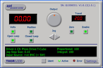
 ズーム
ズーム- 前面パネルにピエゾ素子制御用の速度ホイールとデジタル表示画面
- 2つの双方向トリガーポート(外部機器からの信号読み取りや外部機器の制御用)
- 付属のUSBケーブルでPCに接続
- Kinesis® ならびにAPT™ソフトウェアパッケージに対応
- コンパクトな設置面積:60 mm x 60 mm x 49.2 mm
- 電源は付属しません(下記参照)
K-CubeピエゾコントローラKPZ101は、単軸を手動またはPCで制御します。上面のコントロールパネルには速度ホイールがあり、位置のプリセットに加えて、順方向ならびに逆方向のジョグ動作と双方向の4段階速度制御が可能です。上面パネルのデジタル表示にはバックライトが付いており、メニュー選択により暗くしたり消灯したりすることが可能です。 ユニット前面には双方向のトリガーポートが2つあり、5 Vの外部ロジック信号を読み取ることや、5 Vロジック信号を出力して外部機器を制御することができます。それぞれのポートの機能は独立に設定することができます。
このユニットは当社の新しいKinesisソフトウェアパッケージならびに従来のAPTコントロールソフトウェアに対応します。詳細は「モーションコントロールソフトウェア」のタブをご覧ください。
このコントローラには電源が付属しませんのでご注意ください。対応可能な電源は下記に掲載しています。

 ズーム
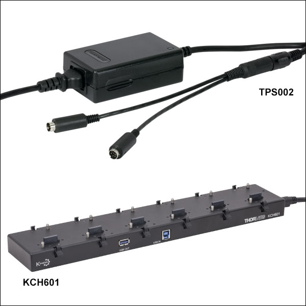
ズーム- ±15 V/5 V電源
- TPS002: 最大2台までのMini-DIN入力端子付きK-Cube™またはT-Cube™用*
- USBコントローラーハブによって電源供給と通信が可能
- KCH301: 3台までのK-CubeまたはT-Cube用
- KCH601: 6台までのK-CubeまたはT-Cube用
TPS002では最大2台までのK-Cube*やT-Cubeに電源を供給できます。K-CubeやT-CubeをPCへ接続するには、個別のUSBケーブルが必要です。
USBコントローラKCH301は3台、KCH601は6台までのK-CubeやT-Cubeをサポートするハブ部分と、壁コンセントに差し込むだけでハブとハブに接続された全てのCubeに電力を供給する電源部分から構成されています。ハブが供給できる最大電流は10 Aですので、お使いになるCubeの合計電流が10 A以上にならないことをご確認ください。こちらのハブをご使用いただくことで、1つのUSB接続によって、複数のK-CubeやT-CubeとのUSB接続が実現します。
接続用USBコントローラーハブについての詳細は、こちらからご覧いただけます。
*電源ユニットTPS002は1台のコントローラ(KNA-VISまたはKNA-IR)、または1台のドライバKLD101にしか電力を供給できません。ユニットを追加すると電流リミット値を超える可能性があるので、そのようなご使用は避けてください。